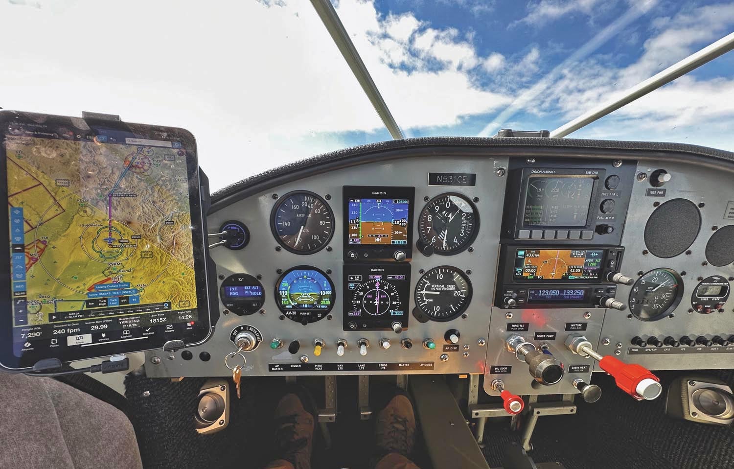
Yes, I finally gave in to the lure of an all-electronic flight panel. Sure, my GlaStar had its share of digital instruments, including a pair of Garmin’s evergreen G5s and a uAvionix AV-30, backed up with a modern Garmin GNX 375 GPS/transponder and GTR 200 com radio. But it was, overall, a hodgepodge—functional, yes, but a real mix-and-match kind of panel. I decided over the winter to change that.
Setting out to thoroughly revise the panel takes more planning than you might think, which is where I want to start this short series. Dynon, like most other EFIS manufacturers, offers its system largely à la carte. You can choose which features to add, at first or later on if you like. Which points up a strong advantage to the Dynon networking philosophy—most add-on modules are connected with SkyView-specific network cables that provide both data and power so adding features later is a whole lot easier than you’d think.
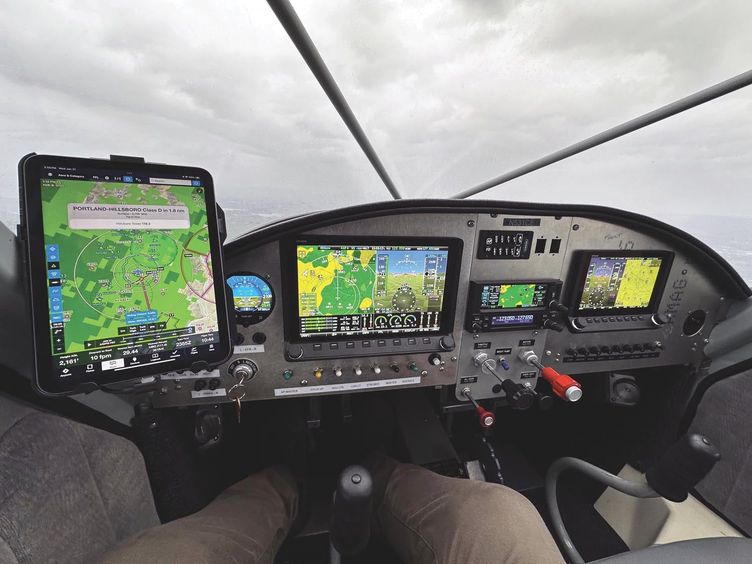
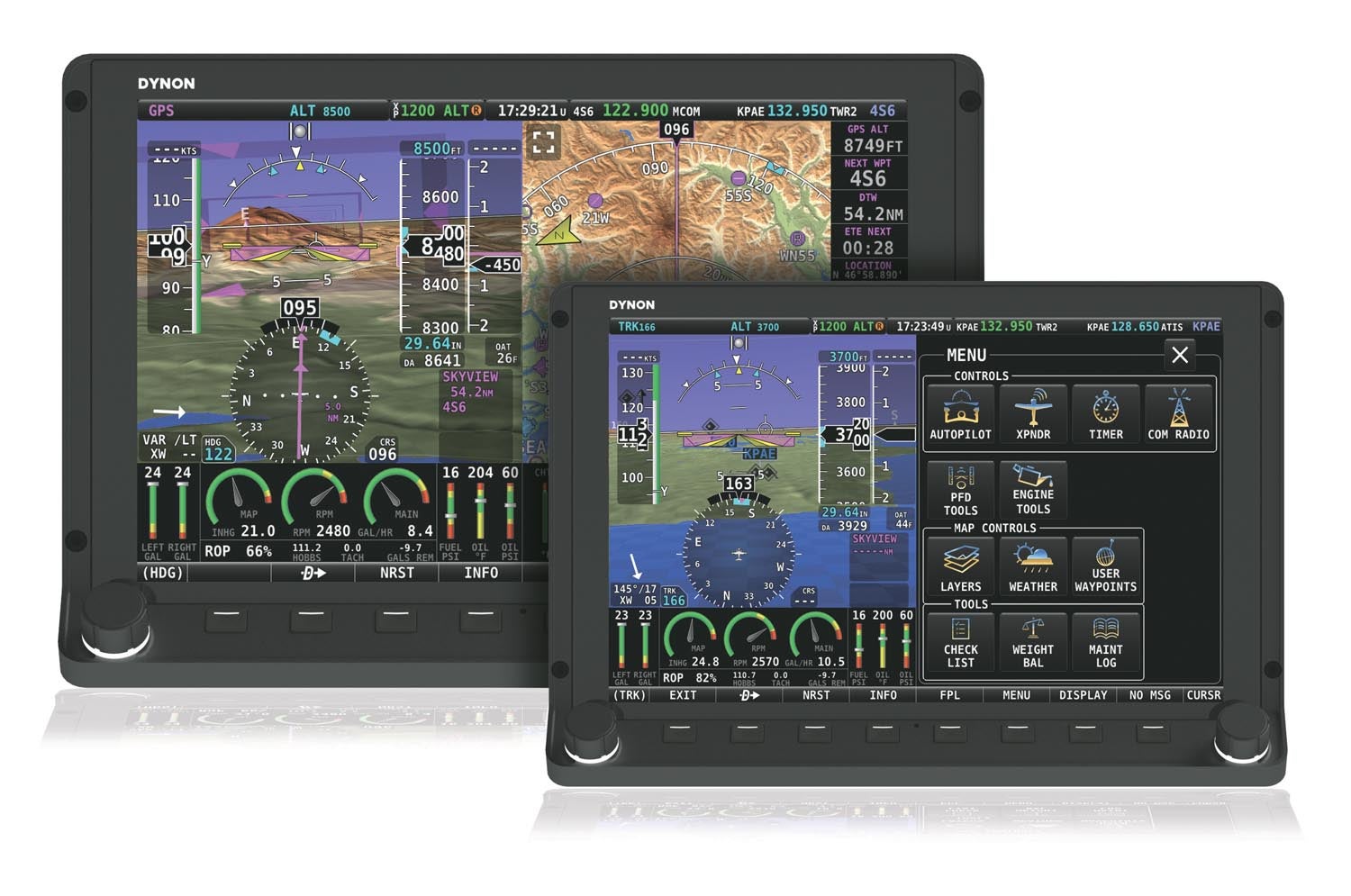
All Dynon SkyView systems start with the screen. For the pilot side, it had to be the large-format HDX1100, with a 10-inch touchscreen as well as a lower bezel with eight buttons and two multifunction knobs. For a VFR installation, a single screen would suffice, mainly because it’s capable of displaying the primary flight display (PFD), the moving map and the engine instruments simultaneously.
So the question is: one screen or two (or more)? One argument is that we’ve come a long, long way with our electronic devices and they’re all amazingly reliable, so single-screen architecture is defensible for a VFR airplane. The opposing argument is that if your one screen fails, you may lose your main PFD as well as all engine instrumentation. You would be forgiven for continuing the flight to a safe landing but you’re not going anywhere after that until you figure out the problem. A second screen provides crucial redundancy as well as a measure of dispatch reliability.
In my case, the unusual layout of my GlaStar’s instrument panel—the center stack isn’t in the center—meant that the larger screen would not fit on the copilot side without relocating the existing electrical harness. That was a bridge too far, so the 7-inch HDX800 was ordered for the right. Because they are connected and share all data, the airplane is fully functional with either screen working.
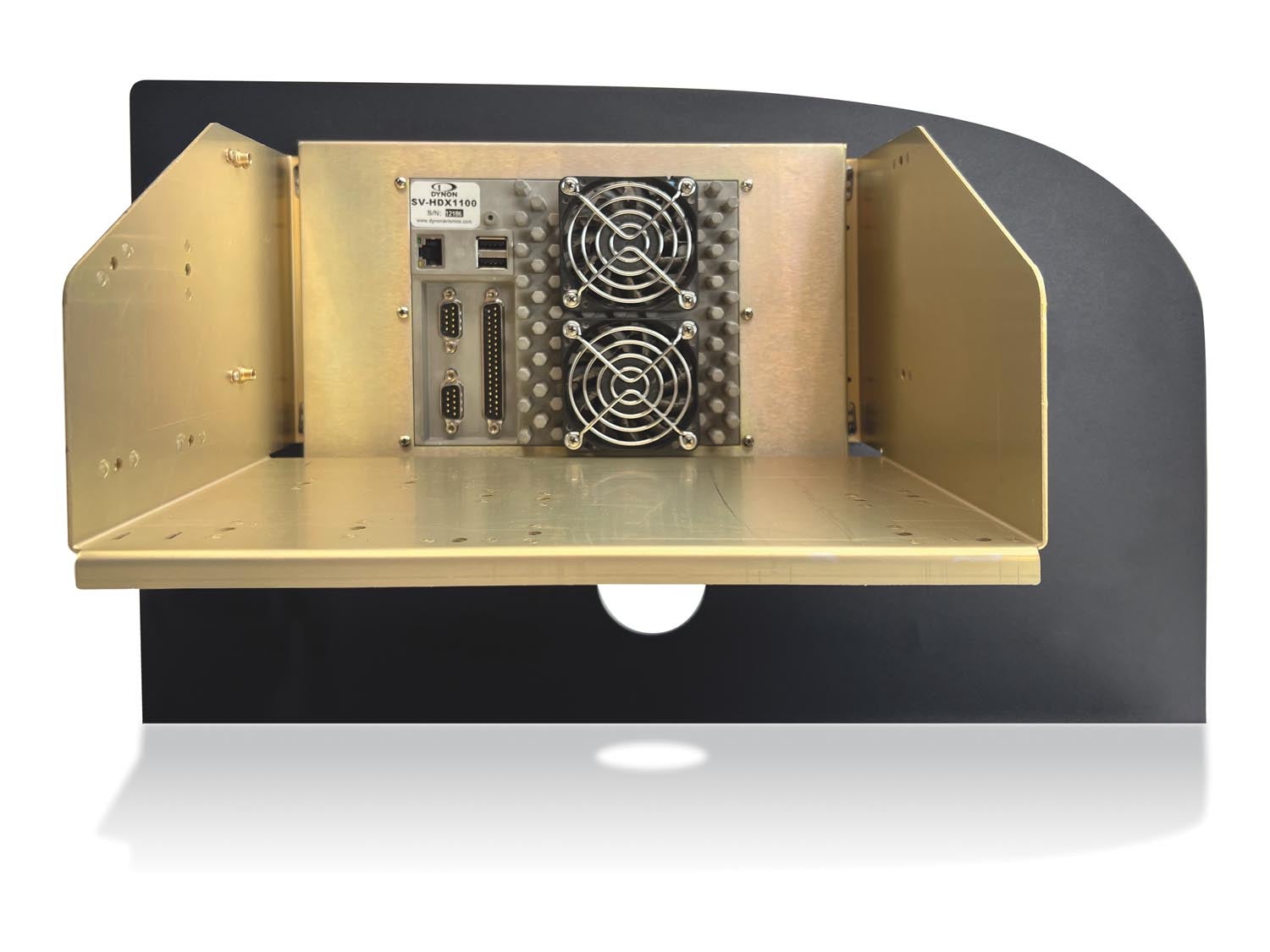
For power redundancy, I elected to run Dynon’s backup battery for each screen. Redundant power is important, partly because most all the components in the SV-NET (the SkyView network) system are powered by the screens. (There are exceptions.) I strongly recommend the battery backup for reliability but also for practical reasons: SkyView takes a few moments to boot and become functional. If you wire the system to the avionics bus, it’ll be about 30 seconds before the engine monitoring is visible after engine start. But with the SV battery, you can wire to the main bus and have SkyView booting before engine start; the battery protects the system from the voltage drop as you crank the engine.
Building Out the Rest
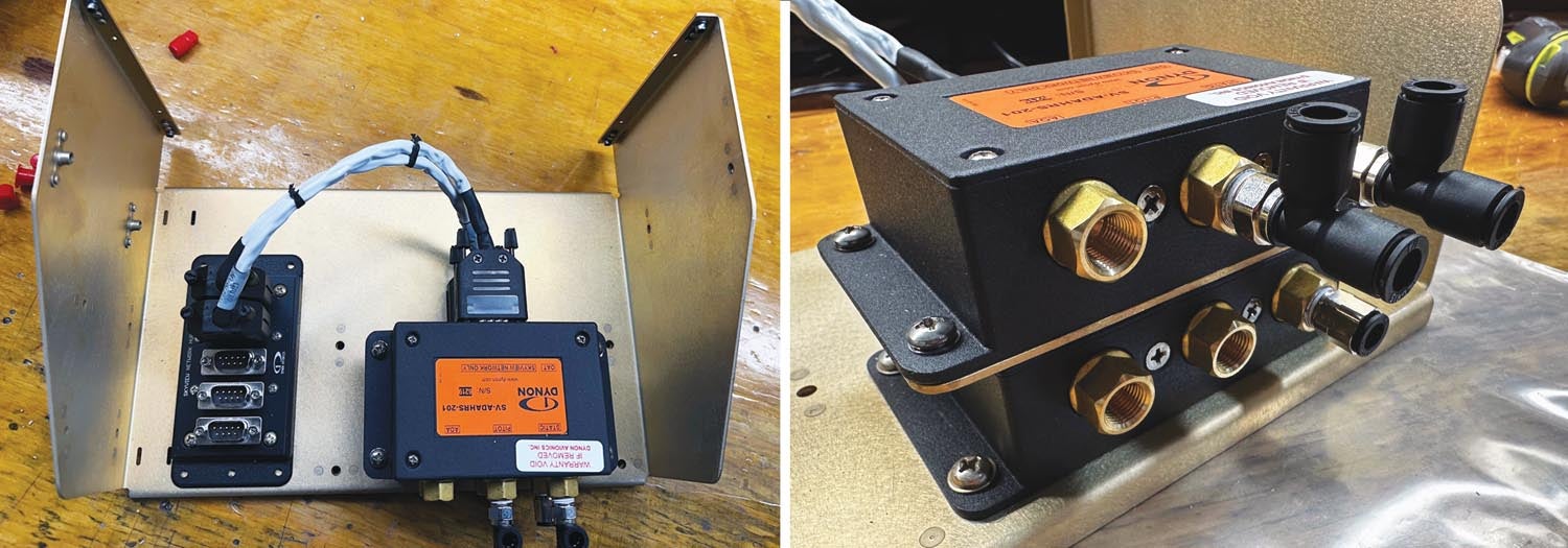
With the screens decided on, you can start to add features. At a minimum, you’ll need an ADAHRS (air data, attitude, heading) module. Dynon offers two. The SV-ADAHRS-200 is your primary attitude/pitot-static module. It also has an internal magnetometer, which means you have to think carefully about where to mount it. Many RVs place the unit just inside the tail cone to keep it away from ferrous metals. In mine, the ADAHRS-200 is on a tray just behind the instrument panel, which puts it right in the middle of the steel tubes that make up the GlaStar’s fuselage cage. I can tell you from experience that’s an ugly place to try to read the Earth’s magnetic field. More on that in a second.
Dynon makes it possible to have redundant ADAHRS modules, so I also ordered the SV-ADAHRS-201. While both are powered up and ready to go, SkyView reads the primary ADAHRS until it detects a failure or discrepancy, then it falls over to the secondary system. And because of where I intended to mount both ADAHRS units, I needed a remote magnetometer (the SV-MAG-236), which I placed in the right wing. (I’ll get into the physical installation issues and lessons learned in the next installment.) Incidentally, you can connect an OAT probe to either of the ADAHRS units or the magnetometer, whichever works best for your installation. I kept my OAT probe location in the left wing root and connected to the primary ADAHRS.
So what else? To make full use of system integration, I went for the Dynon autopilot servos. These have the same footprint as the older TruTrak servos in my airplane (and are similar to Garmin’s, for that matter) so I could swap those out, albeit with a complete change of wiring. What’s interesting is that the SkyView system is functional without a remote autopilot controller—all autopilot features and modes can be managed on-screen—but I was told (and believe) that it works much more seamlessly with one.
Dynon also supports a remote-mount com radio, stereo intercom and transponder. The com radio can have its own control head, useful ergonomically but also for redundancy; as long as the SV-NET system has power, the com box can control the remote radio. There is no remote controller for the transponder, so consider that a display failure of a single-screen system can render the transponder inoperative. Because I had a newer IFR-approved GPS/transponder and com radio already installed, I did not opt for the Dynon products. The HDX will, however, happily control the Garmin GTR 200 via a serial port, though it will not talk with the transponder section of the GNX 375.
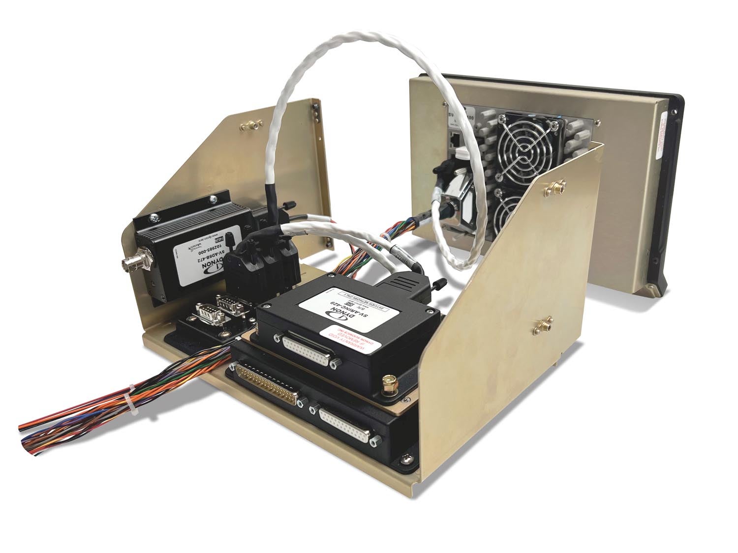
The ADS-B In data from the Mode S transponder inside the GNX is also sandboxed, which meant I needed the SV-ADSB-472 receiver. This gave me a source of traffic and weather to the SkyView system while the GNX 375 will continue to feed GPS and other data to ForeFlight running on an iPad via Bluetooth. Finally, Dynon strongly recommends using its own GPS module. I thought the GNX could easily provide position information for SkyView but I learned that the SV-GPS-250 receiver/antenna module has a much faster refresh rate—5 Hz rather than the more common 1 Hz. In early flights, it was clear that the Dynon GPS locked on fast and responded very quickly. It was a good addition.

Finally, because I needed a way to get the lateral and vertical guidance from the GNX 375 into the Dynon world, the SV-ARINC-429 module is compulsory. (If you have VFR external navigation, you can use the many types of RS-232 data protocols supported in SkyView but, in that case, I’d be happy relying on the Dynon GPS and internal mapping software. SkyView will also accept RS-232 nav data from certain Garmin, Trig and VAL radios.)
I already had a Garmin GAD 29 on board and I feared that I’d have to rewire everything. Nope. Dynon’s ARINC 429 module has the same pinouts as the Garmin box; all I had to do was add one serial wire from the GNX. What’s more, though it’s not super clear in the documentation, SkyView will send baro information for the GNX’s transponder from the ARINC data stream; no need for a separate serial baro connection.
I had a head start on the engine monitoring by already having a Dynon EMS-D10 in the airplane. The SkyView box has the same connectors and essentially the same pinouts—at least all the major ones slide across. (If you had audio out from the EMS, you’ll need to move it to one of the HDX screens, as one example.)
Connection Making

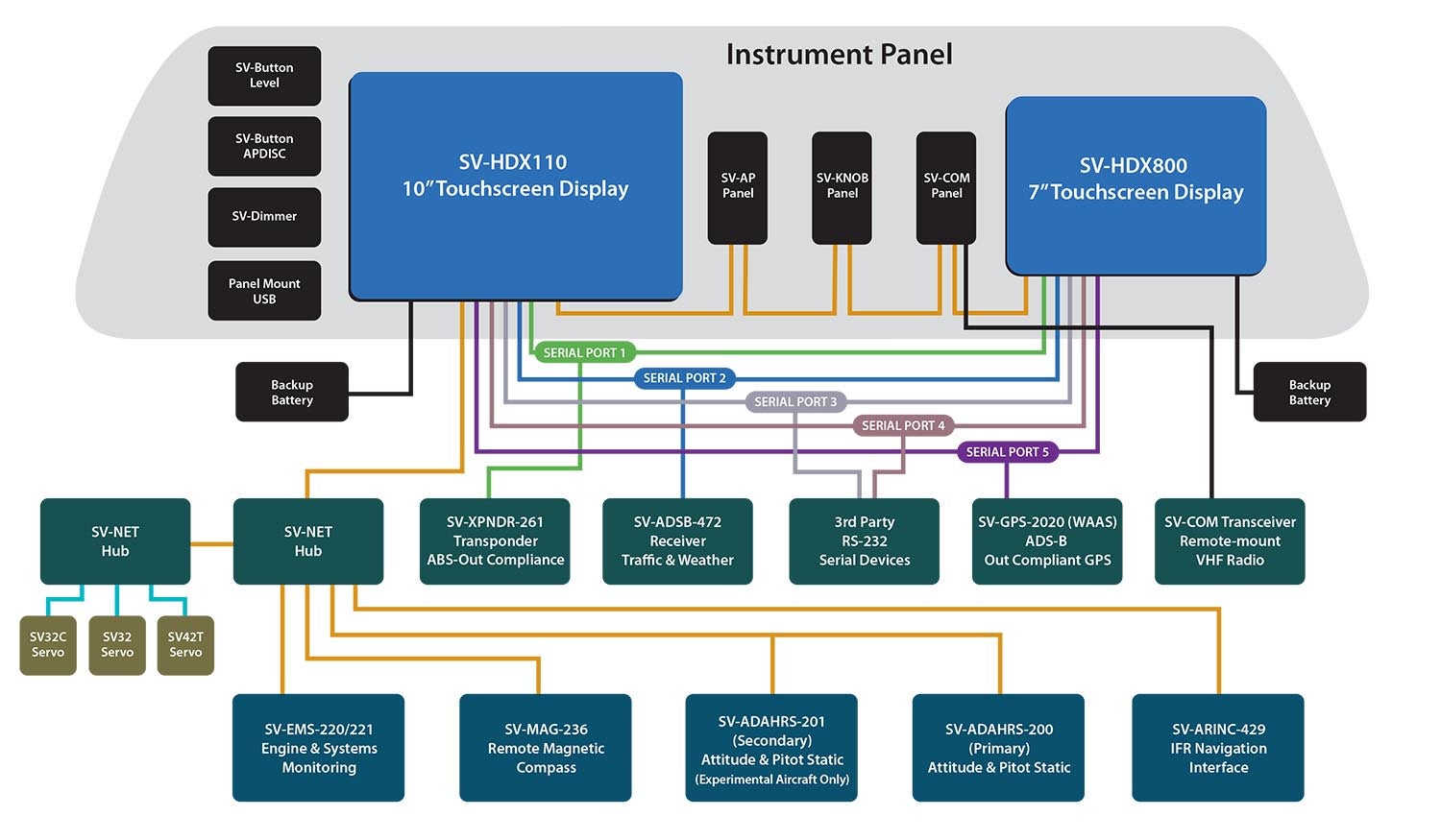
As mentioned, most of the modules in the SkyView world are connected by proprietary network cables. Normally, each is terminated by a nine-pin D-sub connector. (The available cables have all nine pins populated; four for dual-redundant data, four for dual-redundant power and ground, one for a special power wire for the engine-monitoring module.) They’re slightly bulky but that’s because the data cables are twisted pairs to prevent RFI.
Each HDX screen has two SV-NET connections plus an Ethernet connection that can be used to link the two screens. In any case, Dynon says to be sure each screen has an SV-NET connection to the other for redundancy. Power and data are passed through, so either screen can support the whole network. Connecting everything is made easier through an SV-NET-HUB, a five-port hub. I used two, one on each side of the instrument panel. Plus, all three of the remote controller modules—for the autopilot, com radio and the desirable knob set—have dual SV-NET connectors that can act as pass-throughs to daisy chain nearby boxes.
Dynon sells terminated cables in eight lengths, from 6 inches to 6 feet. You can also buy longer cables factory terminated at one end that can be cut to length; these come in four lengths, from 10 to 25 feet. I spent several hours trying to determine how the SV-NET system would be laid out inside the airframe and came close to ordering what I needed. What I can say now—and will elaborate on later—is that it’s not a bad idea to order longer cables than you think you need and re-terminate them to fit. With the right tools, it’s an easy job. Oh, there is also a special autopilot harness available. It differs in the sense that while the servos communicate through the normal SV network they require their own dedicated power, ground and disconnect wires.

Still other components live away from the SV-NET architecture. The GPS module is connected to dedicated pins on the HDX, providing data in and out, power and ground. These connections must be paralleled for each screen. Same thing for the ADS-B receiver and external control of the transponder or non-Dynon com radio. The system supports a wide range of serial-connected devices.
So that’s the block diagram of SkyView HDX. It’s helpful to understand that the system is highly extensible, with the SV-NET system making adding new features relatively painless. Next: cutting metal and figuring out where everything goes in an already-flying airplane.
![[Credit: JetStream Rider]](https://www.kitplanes.com/wp-content/uploads/2026/04/AdobeStock_345999332.jpg?w=218&h=150&crop=1 "2026 Avionics and Lights Buyer’s Guide")
![[Credit: Radiant Technology]](https://www.kitplanes.com/wp-content/uploads/2026/04/550095_5165745cc27748a598699799d796fd94mv2.jpg?w=218&h=150&crop=1 "Radiant Technology Unveils SafeGyro")
![[Credit: Dynon]](https://www.kitplanes.com/wp-content/uploads/2026/04/EMS-stand-alone_HDX.png?w=218&h=150&crop=1 "Dynon Unveils Scalable Engine Monitoring for Kitbuilders")


