It’s hard to believe that several months have gone by again and it’s time for an update. I’ve told Carol many times over the years that I’ve never seen time go by so fast as when I am building an aircraft. I haven’t decided if it is due to the fun factor or that I am so engrossed in it that time flies (pardon the pun). Whatever the reason, here we are a few months and over 250 build hours later. The exciting thing is that it is beginning to look like a real helicopter now, with some painted parts, but let’s go through some of the nitty gritty that got it here first.
Cowlings
Back in Part 2 in the December 2022 issue, I mentioned I was starting on the cowlings. They are complete now, but certainly presented some challenges. They are very well formed out of carbon fiber at the factory, so they are light but also unwieldy at times. Most of the time I am working by myself. Often, for the cowlings, I needed a second set of hands to hold things in place. They not only needed mounting to the airframe, but they also needed some additional openings and access doors added.
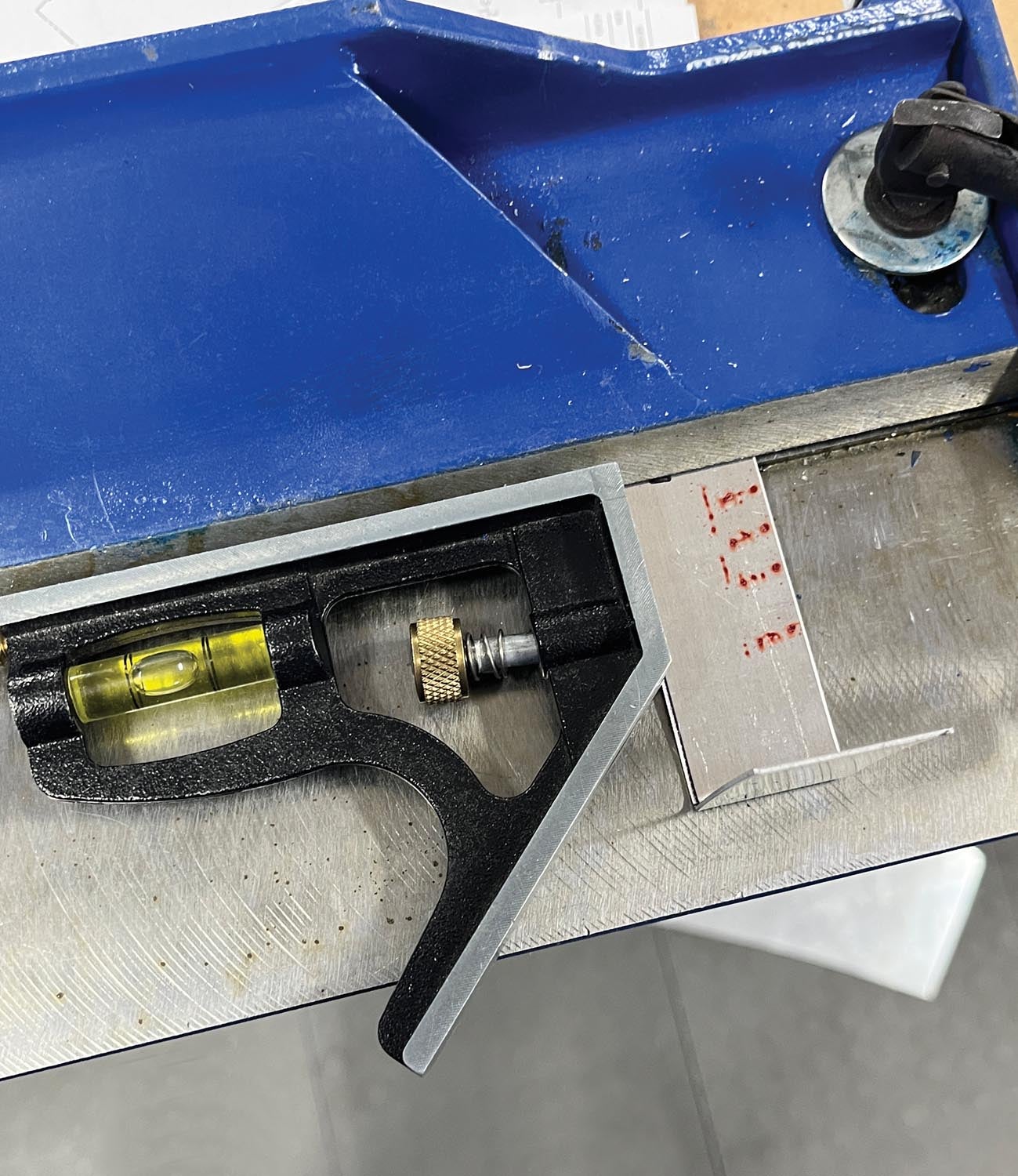
I had to make about a dozen brackets for the cowlings and the metal brake came in handy again. I used a base unit from an adjustable square and held it in place on the brake to form a nice 90° bend to the long axis of the bracket. This method ensured the brackets would be straight when mounted to the tail cone.
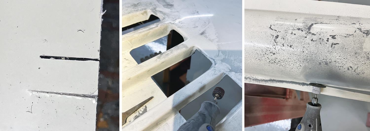
For working with fiberglass, I really like a high-speed, battery-powered Dremel, along with an assortment of various accessories. I find that it’s easy to control and makes small work out of opening up the cooling exits on the cowlings using a cutting wheel and sanding drum. It also made an easy job of cutting the flanges off the premolded tail rotor shaft covers and cutting holes in the cowling for the oil cooler exit air. You can certainly use aviation snips to make some of the cuts, but I wouldn’t recommend them for final cuts in fiberglass as they leave tiny cracks in the gelcoat along the cut.
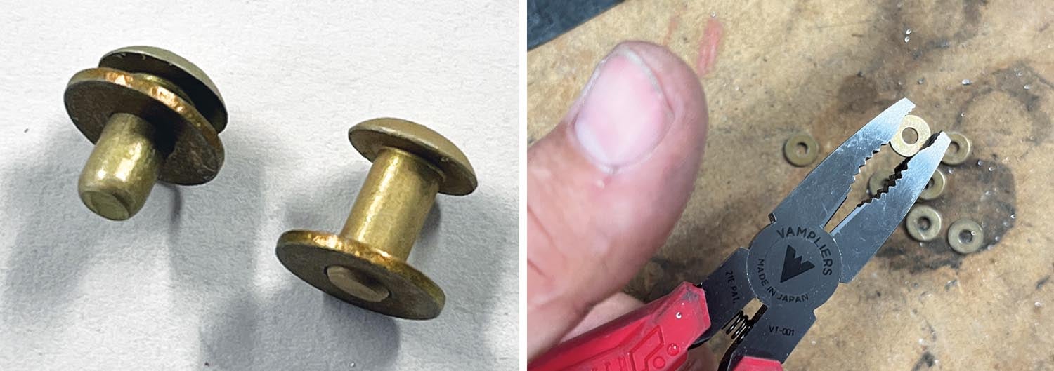
Here’s another trick when working with fiberglass parts that need metal pieces riveted to them, like the oil cooler outlet stiffener and aluminum flanges on the rotor shaft covers. Use soft-set rivets, which can be identified by part number or the lack of a dimple on the head of the rivet. They are made of 1100 aluminum versus the 2117 AD hard rivets, which are used predominantly throughout an aircraft as they are made for structural purposes. Be sure to lower the pressure for your rivet gun when using them, as they will set too flat very quickly with just a few strokes of the rivet gun.
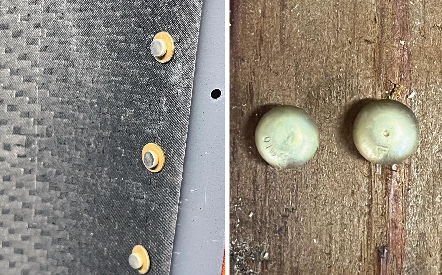

I also use a backup washer on the fiberglass side to spread the load. You can buy aluminum backup washers for this purpose. Since I didn’t have enough here, and patience is not one of my virtues, I made my own by drilling out some #6 AN960 washers. Why did I have to drill them out? Well, a #6 washer has a 1/8-inch-diameter hole, and a typical AN -4 rivet takes a #30 drill bit for the hole, which is just a tad bit larger than 1/8 inch. Vampliers, one of my most useful tools, made holding the circular washer easy while drilling. Due to manufacturing tolerances, not all the washers needed drilling.
You can see this process at baselegaviation.com. Click on the “YouTube Videos” link and scroll down to the “Riveting Fiberglass to Metal” video.
Where’s My Engine?
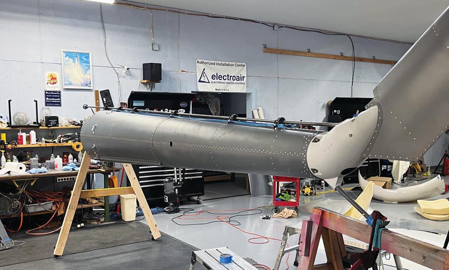
Once the cowlings were completed it was time to remove the tail cone from the main cabin to install the engine, which was the next chapter in the instructions. However, I don’t yet have an engine. I am planning on a Lycoming Thunderbolt IO-540, and as of this writing I am being told that it might be available in December 2022. As seen throughout the economy over the past few years, supply chain issues are affecting everyone in the kit aircraft industry. Not being one to sit around and wait, I decided to move ahead and work around the missing engine. That also meant I got to do some things I really like, such as designing the instrument panel and installing the wiring.
It dawned on me that perhaps I should paint the interior prior to starting the wiring, so I did that. Truth be told, not much of the aluminum interior will show after Carol does her interior magic, but enough would show such that I needed to paint it. I picked a nice day, with warm temps and no wind, and using some Imron silver metal flake I had left over from the RV-10, I completed it in one day.
Panel and Wiring
I used Panel Planner software, which some of you might be familiar with. I’ve used it on my last couple of aircraft. I find it relatively easy to use and Gene Velazquez, the founder, is extremely responsive. As an example, when I updated the software to do this panel, I discovered that the dimensions of the instrument panel were wrong. I sent a note to Gene and he updated it within one day! Another feature I like is the ability to print off the panel “full size.” This allows me to tape the print to the panel in the aircraft and then sit in the cockpit making sure everything will fit and is functional. After three or four variations, I sent the final to Rob Hickman at Advanced Flight Systems, and I hope to see the results soon.
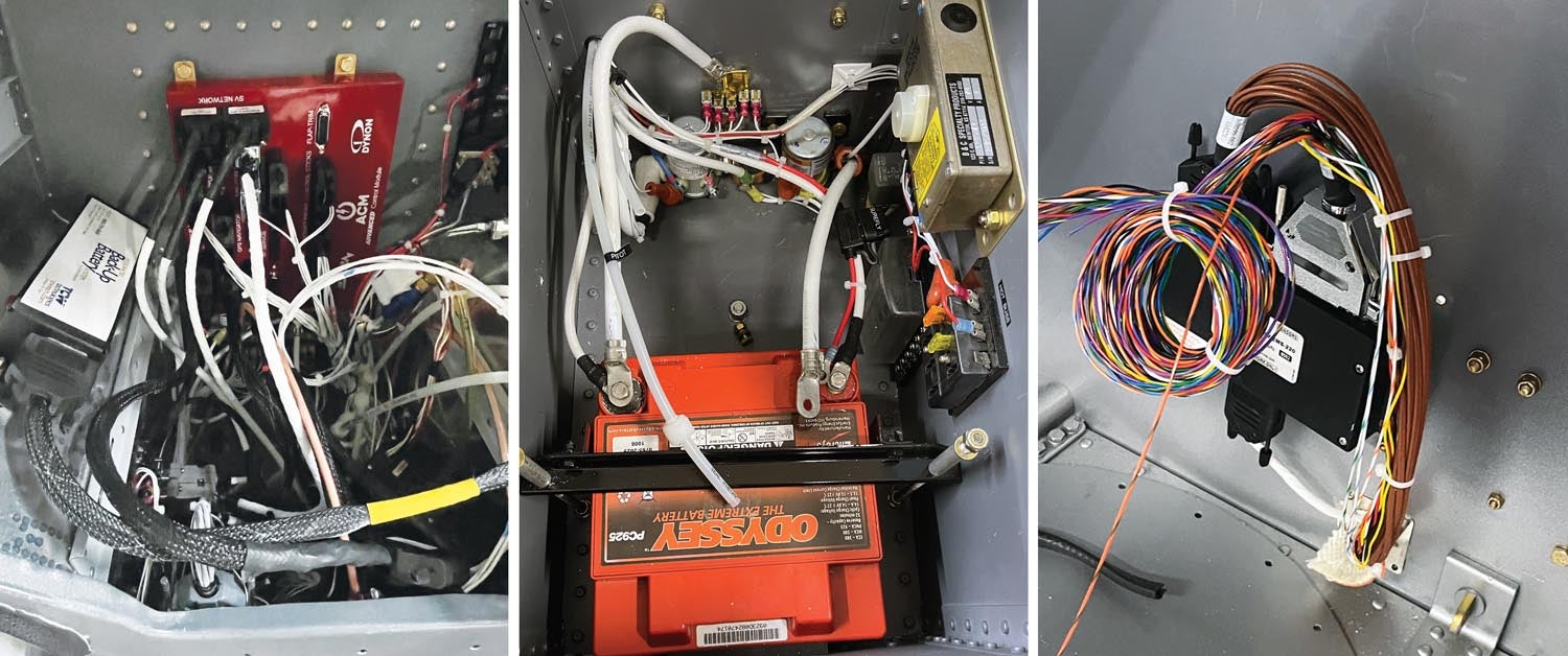
I will be using a single AFS 6600 EFIS as the main display, with a dual engine/rotor rpm gauge, manifold pressure and airspeed indicator as backup. Rob and his team are another example of stellar customer support to aircraft builders. Helicopters need a second oil pressure indication for the transmission in addition to engine oil pressure. Using another input on the EMS module, they are coding this into the 6600 software for me. Speaking of the EMS module—that is the box to which all of the engine sensors are wired, and then it is connected via the SkyView network to the EFIS for display. Since the helicopter engine is quite a distance from the cockpit, I decided to mount the EMS module on the cabin side of the firewall behind the left rear seat. That way none of the engine sensors required any additional length of wiring, thereby saving some weight and eliminating the chances for intermittent connections associated with spliced wiring. I now only needed one 9-wire SkyView network cable from the instrument panel to the cabin firewall instead of approximately 30 wires, not including the 24 CHT and EGT wires that would have needed extensions.
The center piece of the Advanced Flight Systems setup is the Advanced Control Module (ACM), which is a very comprehensive power and distribution center for the aircraft. It eliminates the need for any circuit breakers, thereby saving some weight and complexity. The ACM also displays on the EFIS, so you can see the health of the electrical system. The premade harnesses connect the aircraft and avionics to the ACM, saving time and preventing wiring mistakes. You still must run wires to various components on the aircraft, such as lights, fuel pumps, etc.
Luckily, the space behind the instrument panel on the Hummingbird is cavernous, so I was able to mount all of the remote components such as the radios, transponder and backup battery behind the panel. The ADAHRS, which provides attitude inputs to the EFIS, is mounted on the floor of the center panel console underneath the switches. The ADAHRS also provides magnetic direction information to the EFIS.
With all of the electrical wiring and metal controls in the cockpit, I was concerned that the ADAHRS would not be able to provide accurate magnetic info, so I mounted a remote magnetometer in the tail cone. It requires mounting it within 1° of all three aircraft axes, so with the use of a smart level, I’m pretty sure I accomplished that.
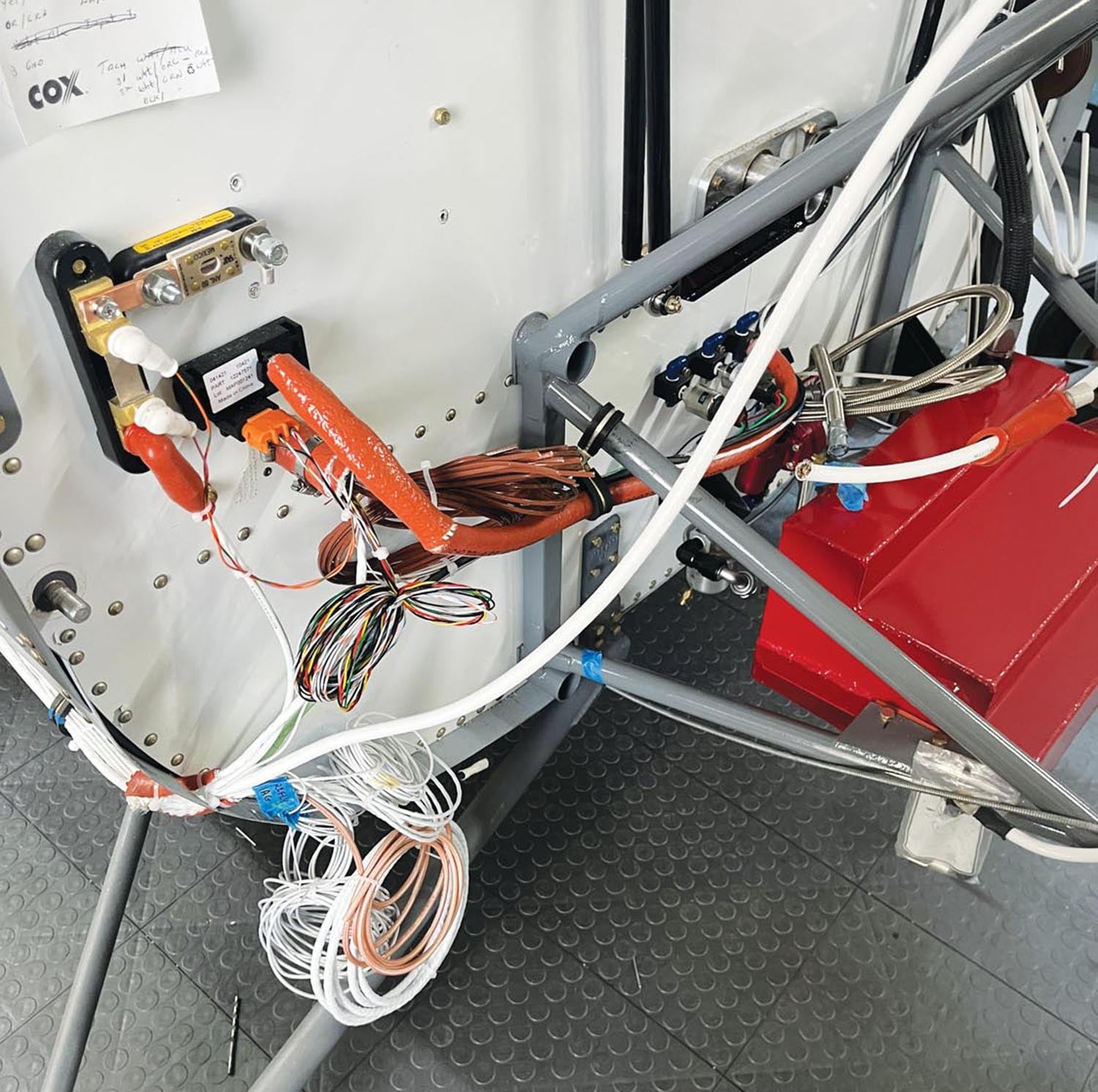
I did make some additions to the electrical system, based upon experience from my other aircraft. For one, I added a hot bus on the main battery compartment so I can have things like cabin lights for night loading of crew and passengers, and USB outlets for phone chargers and iPads, connected without having to turn on the master switch. It also allows for connecting the Lycoming electronic ignition, which is basically a SureFly ignition. I added another “expansion” bus for things like electric seats and some instruments that were part of the kit, like the tach generator emulator and manifold pressure gauge. These bus additions will make adding future components much easier.
Painting the Tail Cone
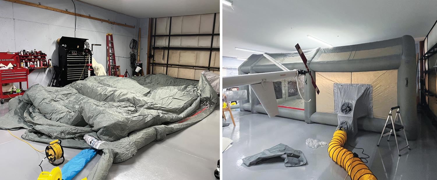
To install the engine, the tail cone had to be disconnected from the airframe. Since I am trying to make progress around not having an engine, I decided it might be a good idea to paint the tail cone. With some wood, a sawhorse and some castering wheels, I figured out a way to support it and make it movable. Since I was going to try a different brand of paint this time, it would give me some experience in the short term prior to tackling the whole project. Our paint design had only one color on the entire tail cone—black. We also decided to not build a paint booth this time, as the last one took up so much room in the hangar for quite a long time. We investigated some “inflatable” paint booths and ended up getting one. So far, I have mixed emotions. It works in that it is only up for the time that you are painting, so that solved one problem. However, the inflation and circulating air require two large and somewhat noisy fans, and you can’t let the inflation fan quit or the whole thing collapses right on your freshly painted surface. We got to experience this firsthand when I unplugged the wrong fan for a couple of seconds to reroute an extension cord. There was lots of panic-screaming and fast-moving hands flying around for a few seconds that seemed like an eternity. The damage was minimal, but lesson learned.
I also learned another lesson about painting something black, although sometimes I admit I am a slow learner. After painting the tail cone, I moved it to the same spot in the hangar as it was previously. It happened to be between the helicopter and a toolbox that I sporadically went back and forth to. After bumping into it a couple of times, I mentioned that I should either move it or at least protect the horizontal stabilizers, as they are sharp and just about at eye level. Sure enough, one day I grabbed a tool out of the box and was walking back to the helicopter with my eyes focused down on the tool, and the next thing I know I am almost lying on the ground. Yep, I walked right into it at a pretty good clip and put a 3-inch-long gash on the side of my head, narrowly missing my right eye. It hurt like hell. Luckily, I didn’t need stitches, but it looks like it is going to leave a scar. Carol has since wrapped the stabilizers with foam, but every time I look in the mirror, I am reminded that I should listen to my inner self sometimes, or at least slow down a bit.
The tail cone came out quite satisfactorily, but not as perfect as I would have liked it, or as nicely as I have accomplished in the past. But I am seeing some of my friends wait a year or more to get their aircraft painted after flying, and then being without it for four to six months. I don’t want to go through that, and I don’t need to win any more trophies. I’m getting more excited that perhaps we can fly it to Alaska, and I don’t want to be too old to do that. It’s nice to have a dream and a goal, as it keeps the fun factor alive for me.
The interior is coming along nicely, thanks to Carol. I’ll leave that story for the next update. Hopefully, by then I will also have the AF-6600 and have power on the aircraft.


