![]() The average builder might agonize over which avionics suite to install but may not spend nearly as much time planning a modern power distribution system to feed it and the rest of the aircraft’s electrics. Sure, you could go with the familiar arrangements of circuit breakers and fuses, bus bars and solenoids, but these days the high-tech trend has switched to self-contained digital smart buses with electronic circuit breakers. The future is here.
The average builder might agonize over which avionics suite to install but may not spend nearly as much time planning a modern power distribution system to feed it and the rest of the aircraft’s electrics. Sure, you could go with the familiar arrangements of circuit breakers and fuses, bus bars and solenoids, but these days the high-tech trend has switched to self-contained digital smart buses with electronic circuit breakers. The future is here.
Two worthy systems—the Vertical Power VP-X/PPS and the Advanced Flight Systems ACM Advanced Control Module—take power distribution to a higher level and display real-time detailed bus data on a dedicated page on a wide variety of third-party EFIS screens. The Advanced product even serves double duty as an avionics wire hub, complete with prefab harnesses. Herewith is a technical dive into each, how they differ and how you might choose.
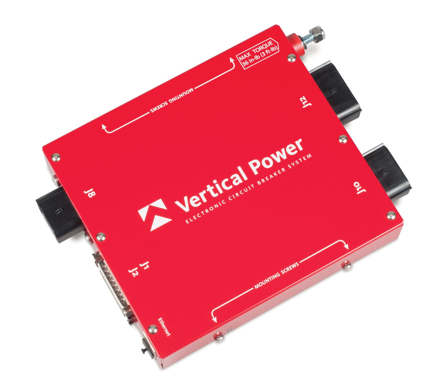
breakers. Vertical Power’s VP-X is a digital avionics bus, with electronic breakers controlled on third-party EFIS displays.
Vertical Power
Kirkland, Washington-based Astronics acquired the assets of Vertical Power Electronic Circuit Breakers back in 2013, and the current Vertical Power products are sold through an established distributor network, including Aircraft Spruce, Gulf Coast Avionics, NexAir Avionics and SteinAir, to name a few. There are two main products in the Vertical Power line—the PPS and VP-X—and both work hand-in-hand or stand alone.
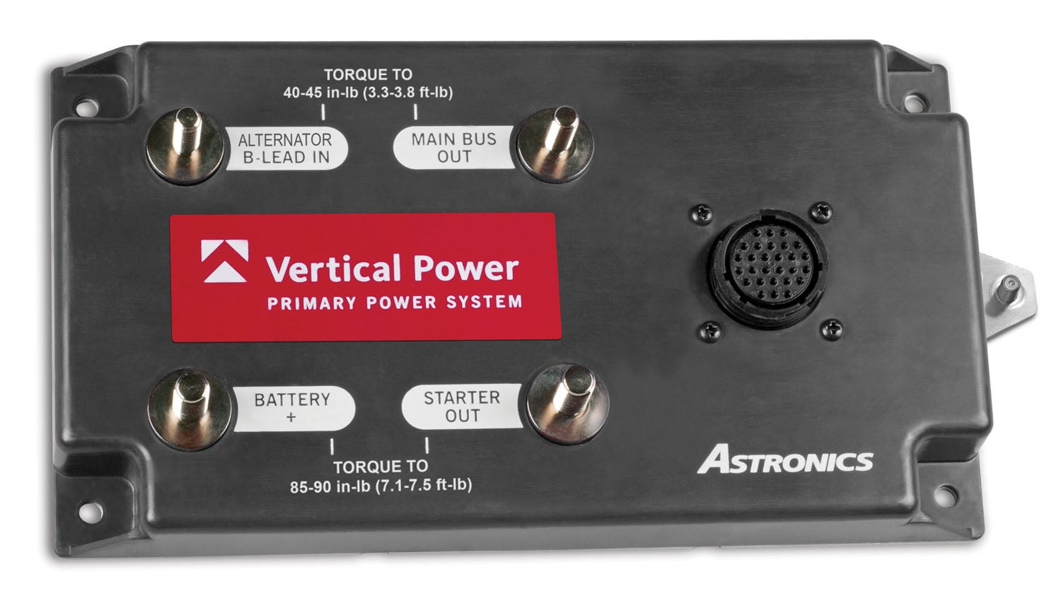
The $1695 PPS, for Primary Power System, came to market a couple of years ago and fills in the gap between the company’s VP-X electronic circuit breaker system and the aircraft battery. The PPS module measures 4.7×8.6 inches, weighs 1.6 pounds, and generally mounts to the aircraft firewall. The PPS works in 14- and 28-volt systems, has solid-state circuitry and controls power from the battery to the starter and the main bus. It also ties into the alternator B-lead(s) so that alternator power can both charge the battery and provide power to the main bus. There’s a single connector for the PPS.
The PPS functions as a single-bus architecture and supports a single battery and one or two alternators. You can also tie in small backup batteries (and electronic bus circuits) directly into the PPS via the battery terminal. It’s important to mention that a single PPS isn’t a true dual-bus system, although you can use dual PPS modules to create one. Perhaps what we like best is that the PPS has digital fault outputs to warn of an alternator failure.
The PPS comes with everything you need to install it, including a hardware kit for mounting the module and a wiring harness kit with the accessories needed to wire the J1 circular connector. The wiring includes terminals that are already crimped on one end. The PPS uses a dedicated external master switch (or switches if you want redundancy), which makes a connection to ground to turn the system on. The installation manual has good diagrams and offers two ways to wire the PPS with the company’s VP-X or with traditional electrical buses.
As a planning sidenote for very basic installs, consider if you want an ammeter on the main bus because the PPS provides the alternator current (shunt) output for showing the amount of current the alternator is providing to power the systems and charge the battery. If you have the VP-X system, the total current reading shows the total amount of current draw of the devices attached to the VP-X. For an EFIS interface, there’s a dedicated VP-X page that shows individual device current as well as total current through the VP-X. The EFIS also has an amps gauge that reads directly from the shunt.
The PPS has an 80-amp continuous main bus output, 80-amp continuous alternator input and a 300-amp max-continuous starter output—and you can use it with dual-alternators connected in parallel. But the PPS only scratches the surface of electronic power distribution. The interface is really expanded with the company’s VP-X Electronic Circuit Breaker system.
VP-X: Circuit Protection on Steroids
The Vertical Power VP-X Electronic Circuit Breaker System is a separate product that takes power from the PPS and intelligently distributes it to all the electrical devices on the aircraft—including avionics, of course. It also provides on-screen control of the electrical system. Vertical Power said roughly 30 OEMs use the VP-X Sport as standard equipment. You don’t need a PPS to use the VP-X.
There are two models to choose from: the $1695 VP-X Sport and $2395 VP-X Pro, which differ by electrical system compatibility (the VP-X Sport is for 14-volt systems only, and the Pro works in 14- or 28-volt systems), the number of available circuits, processors and power supplies (the Pro has dual processors and dual power supplies for redundancy). The physical installation for both products is identical, as is the setup. Both the Pro and Sport compact modules have dual 25-pin D-sub connectors and can be mounted behind the instrument panel or any place suitable for remote avionics and accessories. There are six connectors on the VP-X Pro and five on the VP-X Sport. Three of these connectors carry high-current loads, and two D-subs are used for low-current systems, including trim motor, as an example. An Ethernet connector is for Windows-based configuration and software updates.
The VP-X Pro has 32 switched power inputs (24 circuits on the Sport model) and what Vertical Power calls Dual Bank technology, or two independent power banks in a single system for redundancy. This isn’t a true dual-bus system (the company dropped that language used on earlier products), but the VP-X Pro has dual banks. This means you can divide avionics and other electrical loads between those two power banks, and in case one bank controller fails, the other bank will continue to operate independently.
You still have the same single-point failure problem you would with a traditional power bus, of course. If the main power supply to the VP-X (contactor, battery, etc.) fails, you’ll still lose the main bus. Don’t throw those battery-powered backups away, and even consider an additional fuse block for some systems. Still, we like the VP-X’s ability to precisely monitor the connected systems thanks to a built-in microprocessor checking each circuit 100 times per second. If there’s an issue with the circuit, there’s a timing component for detecting short circuits, plus its ability to precisely measure voltage and current on every sweep. The EFIS throws a fault message to get your attention to go to the main electrical page where you’ll get more information on the use—short circuit, overcurrent, overvoltage, etc. You’ll know what has tripped, why it has tripped and should have plenty of clues to help troubleshoot the issue. The VP-X also makes it easy to load shed without killing the entire avionics bus.
Don’t overthink the interface overall, and when installing the avionics and a VP-X, think in terms of wiring to a traditional power bus with mechanical circuit breakers or fuses. Simply wire the power input from the avionics component into the VP-X. Each bank of circuits is powered by an independent power supply and a microprocessor, and you wire the avionics master in as a main switched input. You can get creative and highly configure the circuits. Vertical power offers generic wiring harness kits (starting at $625) that come with all of the wires (with Molex and D-sub connectors) on one end that connect to the VP-X device. There are four major connector inputs on the VP-X Sport and five on the VP-X Pro. It’s said that a VP-X can save as much as 60% installation time over a traditional bus arrangement, although there will be an initial learning curve.
There are no relays or solenoids in the PPS or VP-X. Moreover, the two banks (A and B) do not share common components on the circuit board—each bank is isolated from the other outside of the main power bus input and ground. We like that either bank can power the aircraft’s starter circuit, so you should always be able to get an engine started if one channel fails. Of course, you could still have a failure of the master switch or battery contactor, but these are relatively rare.
But what isn’t rare with amateur-installed avionics is the failure to fully read the installation manual, including the footnotes in the wiring schematics and pinouts. The install manuals for the Vertical Power equipment are quite good, and we spotted some important warnings, especially when connecting the systems with B&C alternators and voltage regulators. As one example, when using the PPS with the B&C LR-3C external voltage regulator and a traditional electrical bus, it’s imperative you wire it per the print in the manual. Not doing so will damage the PPS and void the warranty. No questions asked.
But wired correctly and for controlling specific systems, there’s plenty of fail-safe, and the manual offers good suggestions on how to build the perfect bus to plan for belt-and-suspenders backup. For instance, radios, lights or displays can be divided up between power banks A and B so that each bank has one of each type of device. That way, if a bank fails, the redundant device on the other bank still has power. You can do plenty of customized configuring. For example, if you have two com radios or dual navigators, put one on each bank. If you have a separate taxi light and a landing light, put one on each bank. But use caution—some systems have dual power inputs (including some Garmin navigators)—and both power inputs need to be on the same bank.
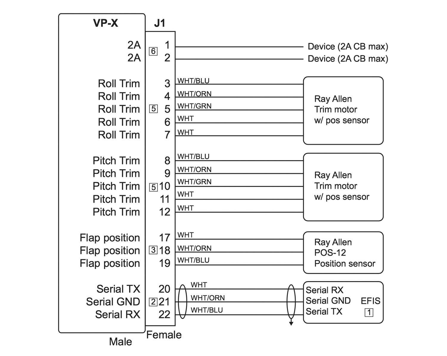
The VP-X systems offer total solid-state systems control, including flaps (with motor and flap position feedback) with a 14-volt regulated pitch trim motor output, plus backup and runaway trim protection. The compatible interfaced EFIS will display on-screen trim and flap position, plus you can even disable the flaps-down command above a certain airspeed. You can also set the VP-X to disable the starter when the engine is running while also triggering a starter-engaged annunciator. Got lights? You can control them with a VP-X, which also has a built-in Wig-Wag modulator.
EFIS Interfacing: Good Compatibility
It’s refreshing to see generous compatibility between the VP-X Pro/Sport and a wide variety of EFIS models—including the Garmin G3X Touch. The system tightly integrates with the EFIS for command and control of each connected circuit (including breaker reset), current draw, starter engagement, plus the disposition of flaps, trim and alternator charging status to scratch the surface of available data. Over 4000 VP-X systems and roughly 300 PPS units are currently in service.
Compatibility includes the Advanced Flight Systems AF-5000/4000/3000 EFIS, Dynon SkyView HDX/Touch/Classic systems, Grand Rapids Technologies Horizon HXr/HX and Sport SX, the Levil Aviation iLevil3 SW/AW displays on iPad, the MGL Avionics EFIS Touchscreen, Voyager, Xtreme EFIS and Odyssey MKII, and the Garmin G3X Touch and legacy G3X.
We strongly suggest using the online planning tool, which is designed to help build a custom configuration of the avionics wiring and electrical system, plus it’s a way to get customized wiring diagrams and pinouts that complement the install manuals. Visit verticalpower.com.
Advanced Flight Systems ACM
The ACM, or Advanced Control Module, has been a popular choice among builders looking to simplify the wiring process while leaving room for future growth potential. While the ACM functions as the main power distribution center for the aircraft’s electrical system (much like the Vertical Power system), it takes the interface one step further and functions as a complete avionics wiring hub. Think plug-and-play for initial avionics interfacing and an easy path for an upgrade later on as you add more avionics.
The ACM was previously available in two different versions—fused or with electronic circuit breakers, but now the company only offers the version with built-in circuit breakers. The ACM-ECB (electronic circuit breakers) is a solid-state system that replaces traditional bus bars, thermal circuit breakers, fuses and mechanical relays. The electronic circuit breaker module has internal circuit current monitoring and is intelligent enough to automatically shut off a circuit if the current is too high, as we’d expect. Like the VP-X, with the ACM-ECB you can monitor the displayed current of each circuit and reset any tripped circuits directly from the EFIS. That’s a huge benefit of either system, in our estimation, and while the data may be displayed slightly differently depending on the EFIS, the concept is the same throughout—detailed on-screen bus and current monitoring.
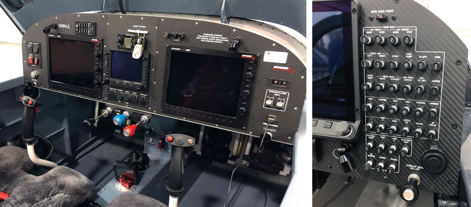
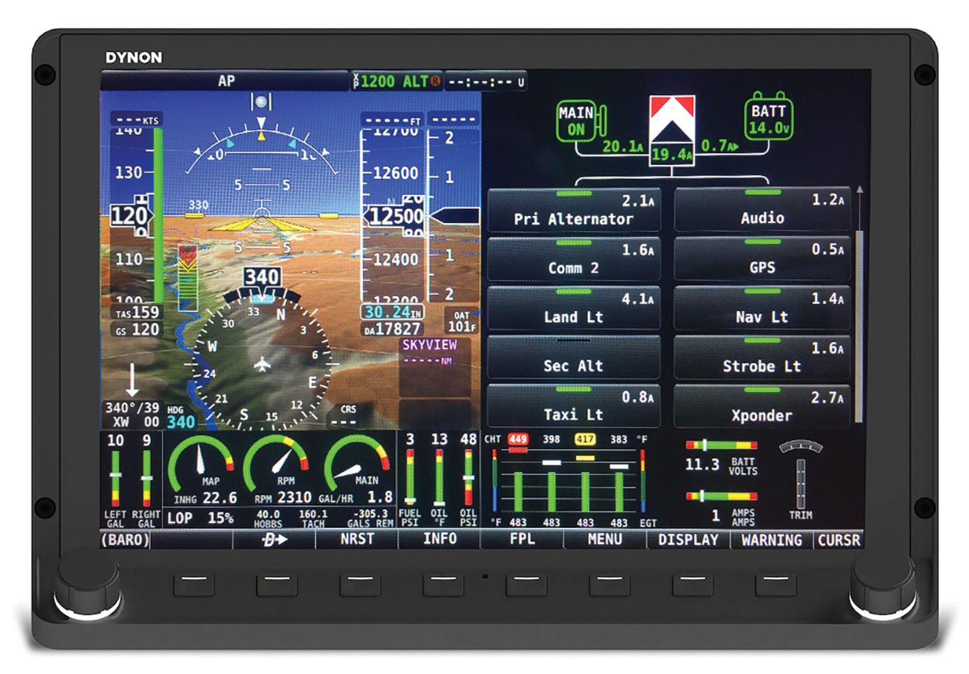
As an example, on an electrical page within the Advanced Flight EFIS, a red bar over an interfaced component indicates that the circuit is tripped, and at the bottom of the page is critical information on that circuit. There’s the circuit’s name, amperage rating, the controlling external command switch and the circuit status (“pulled,” for example). A green bar over the device, as another example, indicates that the circuit is turned on, while the amount of current being used is displayed to the right of the circuit’s name—PFD EFIS 2.3A. You can also change the value of the circuit breaker (configurable in 1/10 amp for each circuit) and, of course, manually trip the circuit. Eyeballing the Dynon SkyView electrical page, we’re impressed with a decent graphic that shows the total ACM-ECB’s current draw and the precise input voltage. It’s possible to configure the ACM-ECB circuit breaker sizes in 1/10-amp increments for each circuit. Also handy is that the flaps circuit also has on-screen buttons that enable you to move the flaps up and down independent of the control stick or panel flap switch.
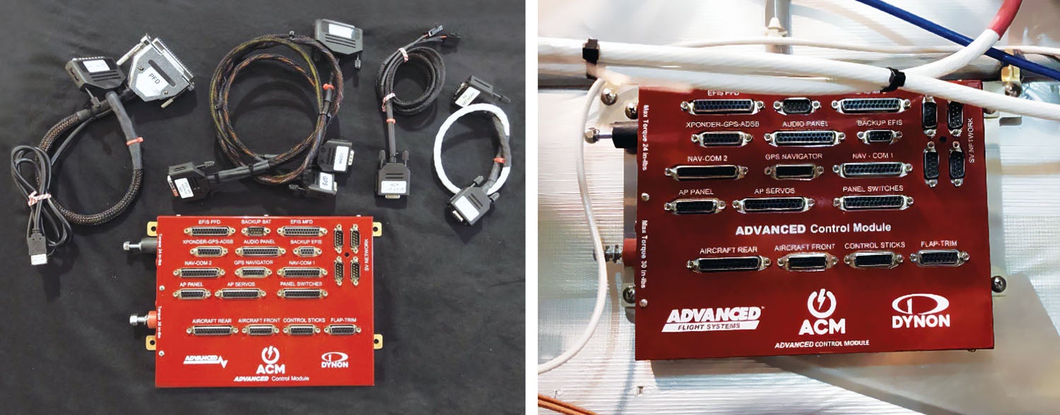
EFIS interface aside, the ACM is the main power distribution center for the aircraft’s electrical system. In a full-up interface, the avionics, headset audio, aircraft lights, autopilot servos, trim servos, flap motor, control stick wiring and the panel switches all get connected to the ACM—all plug-and-play. And there is plenty to plug in—27 channels of input circuits—from the EFIS (primary and backup) to alternator, starter, boost pump, landing lights (including an airspeed-controlled wig-wag feature) and aux power. Since Advanced Flight Systems is part of Dynon, the ACM uses Dynon’s SV-ARINC module built in.
The ACM can be used with either Advanced Flight Systems’ standard switch modules (using a 25-pin ribbon cable), or you can use custom switches wired to the ACM, using the system’s 25-pin D-sub connector designated for external switches. The switches are high-quality lighted rockers for use as the primary master, alternator, autopilot, avionics, fuel boost pump—those kinds of functions. Worth mentioning is that Advanced Flight makes it clear that the ACM-ECB should never be utilized to power anything critical to the engine’s operation. This includes electronic ignitions, electronic fuel injection and high-pressure main electric fuel pumps.
Easy Connect
The physical installation is straightforward, and the ACM with electronic circuit breakers weighs roughly 2 pounds and generally mounts on the instrument subpanel behind the EFIS PFD. The install manual has good examples for installing it in popular kit models, including lots of Van’s. In addition to drilling an attachment point for the ACM in a logical spot, you will also need to drill the subpanel for the ACM ground wire. Primary electrical connections are pretty simple—connect the main power wire from the battery master relay to the red power lug on the ACM, and connect the ground power wire from the airframe ground to the black power lug on the ACM.
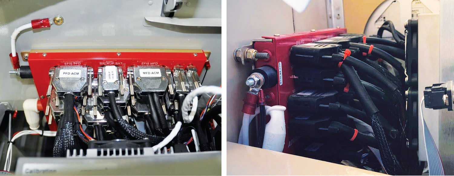
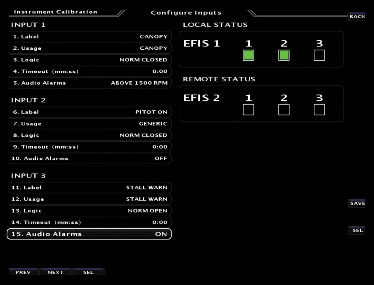
The various aircraft system inputs are fed to and from the ACM with supplied harness connectors. The fuel pump, alternator and starter come in on the Aircraft Front harness; flap and trim motor wiring come in on the Flap and Trim harness; and autopilot servos come in on the ACM’s Servo connector. Even the control stick wiring interface comes in a dedicated Aircraft Control Stick connector on the ACM. There’s also a pitot, static and AOA connection to the installed ADAHRS. Configuration for some EFIS models using the electronic circuit breaker ACM is done, in part, the old-fashioned way with configuration switches on the back. The switch settings control how the EFIS PFD and MFD serial ports are routed to the attached devices.
We like that the ACM install manual talks through a good portion of the Advanced Flight Systems and Dynon EFIS installs, with close reference to the ACM interface. We think the drawings are good, and Advanced uses simple language—just what builders want. And builders also want a simplified avionics installation, and that’s a big advantage of the Advanced ACM. It’s a prefab concept.
“One of the major advantages of the ACM-ECB is we provide premade switch modules that connect to the power module with a single ribbon cable, eliminating all of the complicated switch wiring,” Rob Hickman, Advanced Flight Systems President, told us. We know from experience that the wiring of an avionics suite from scratch, no matter how simple the manufacturer makes the interconnect, can result in mistakes. Advanced is trying to tame that dragon by using the ACM system in its Advanced Panel process, where the company turns out a completed panel and all the major systems are provided with premade harnesses. The current Advanced Panel program is available for a wide variety of kits—the majority of Van’s models, the Glasair Aviation Sportsman and GlaStar, Lancair, Sonex, RANS and CubCrafters, plus it will work with other projects.
The ACM with and without electronic circuit breakers is used in the Advanced VFR and IFR panel options at various price points, depending on the level of construction and equipment required—either Dynon or Advanced Flight Systems suites. Speaking of pricing, as a standalone system, the ACM-ECB is $2750, and Advanced says it only sells the device with prefab harnesses. Substituting a $2195 VP-X Pro in a Dynon or Advanced Flight Systems EFIS suite, the required ARINC adapter, network hub and VP-X license fee comes to $3045.
Advanced Flight offers what it calls the ACM Jump Start Kit, which is essentially the foundation for the aircraft’s electrical system and panel wiring. It includes the ACM-ECB and everything you need to connect a Dynon SkyView system or Advanced AF-5600 to the EFIS backup battery, transponder, ADS-B receiver and Dynon’s SV-GPS module using a plug-and-play premanufactured harness. It’s $3050 for the package. More information is available at advancedflightsystems.com.
Conclusion
When it comes to microprocessor-based, self-contained power distribution, it’s logical to be concerned about reliability. Yes, lots of eggs in one basket. We’ve troubleshot enough electrical systems to know that mechanical components aren’t exactly reliable, either. Still, we’ve heard of growing pains with early generation Vertical Power products, but the current-generation VP-X Pro and VP-X Sport have been significantly reengineered, we’re told by the company, and field reports we’ve received have been positive. Gone is the ZP-200, an early version with a dedicated display.
Which you choose—the Vertical Power VP-X/PPS or the Advanced ACM—might depend on how you plan to interface the avionics in the kit. Remember, with the Vertical Power VP-X you still need to wire all the ARINC and RS-232 data lines, the audio system, radio stack, intercom and wire all the power for these devices to the VP-X module and program it all with a PC. (Incidentally, there are options from Approach Faststack, which offers wiring hubs but not power distribution systems. We’ll look at those in an avionics hub roundup article.)
Frankly, we wonder why every builder wouldn’t at least consider either of these products, including the Vertical Power PPS as standalone and the Advanced ACM-ECB for the avionics and accessories. Better is that the systems work with a wide variety of third-party systems—even Garmin. We’re all for eliminating long runs of wires, relays and other hardware in the airframe. Plus, the smart current-limiting ability of CPU-based electrical distribution can add another layer of safety and backstop, while EFIS software integration shows you a healthy level of useful bus data. That’s convincing enough for us.
Photos: Larry Anglisano and courtesy of the manufacturers.
![[Credit: JetStream Rider]](https://www.kitplanes.com/wp-content/uploads/2026/04/AdobeStock_345999332.jpg?w=218&h=150&crop=1 "2026 Avionics and Lights Buyer’s Guide")
![[Credit: Dynon]](https://www.kitplanes.com/wp-content/uploads/2026/04/EMS-stand-alone_HDX.png?w=218&h=150&crop=1 "Dynon Unveils Scalable Engine Monitoring for Kitbuilders")


Very much enjoyed this article. Well summarized and packed with information. “If” I was going to kick off another build project, I’ll be going back to this review. thanks.
After spending many long months wiring my RV8, I am seriously looking into using the VerticalPower box for my next airplane project, if there is a next airplane. I don’t regret doing everything by hand because it was a great learning experience.
From a photo caption in the article: “We give the PPS an edge in perceived reliability.” How do you “perceive” an edge (and how do you quantify it?) in reliability for a product whose inner workings are unknown to you? Unless you’ve examined and tested the code running inside the PPS (or the ACM), or read the datasheets for its components to discern MTBF predictions, how can you make *any* assessment of its reliability? The assembly of discrete components that you compare it against are all well characterized over decades of service in GA aircraft. They require no software (or software updates) to operate, and if something does go wrong with one of them, replacement parts are available from suppliers everywhere. Furthermore, their failure modes are few, well understood and easily tested in the field. If a system like the PPS or ACM has a failure, how will it manifest and which systems will it affect? How long will it take and what will it cost to remove the box, ship it to the manufacturer for repair, ship it back and reinstall it? How long will the manufacturer support it (Garmin, anyone…)?
These products are intended to appeal to builders who are uncomfortable with the skills or time required to wire an aircraft, and to system integrators who work for airframers and avionics shops. That’s fine, and I understand the appeal, but let’s not pretend that we’re gaining reliability just because it’s easier to install or because the manufacturer of the gadget says so. Maybe they are reliable — I certainly hope so — but I have yet to see an article about them that asks the manufacturer any hard questions about how they proved it.
I asked tough questions. Vertical Power said it designed the products to certificated standards, but since it’s an experimental product and nobody wants to pay for the full TSO process, it fell short of the full-up certification proving process, although it did conduct heat/burn testing. It spent five years developing the PPS with 27 months of beta testing with close to a dozen units in all conditions around the world.
In-house testing consisted of high loads, high voltage, climate, and destructive testing with solvents, oils, water.
Builders I surveyed are pleased with the reliability, simplicity and support of the latest-gen Vertical Power products.
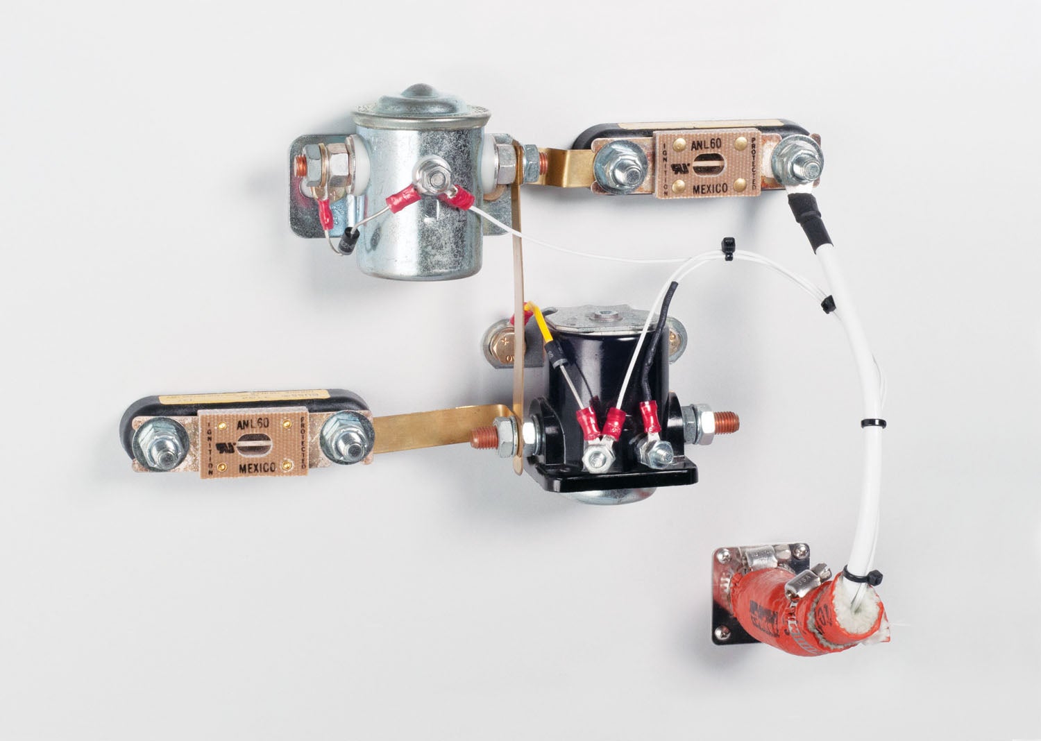
$1,700 vs about $200 for 2 contactors, a current shunt, [ not shown in the pic ], and a 60-80 amp breaker in the panel.
As an electrical engineer/ pilot/ a/c owner, I’ll take the latter. Contactors will last 50 years, are simple to connect with 2 wires…
So, it’s a few more holes to drill and a couple of extra connections.
My experience is that electronics will not likely live for 50 yrs, especially when exposed to the 180 degF heat under the cowl….!!
Comments are closed.