At the end of the last installment I was getting ready to start on the control system. While things have not gone as fast I would like, good progress has been made. There were some interruptions, with us heading to Alaska in the RV-10 during the last week of June. That was truly a wonderful trip, and we got back to Atlanta with a week to spare getting ready for AirVenture. The RV-10 is truly an amazing traveling machine, enabling us to have breakfast in Ketchikan one morning and dinner at home the next evening! But, truth be told, for a good portion of the time while we were in Alaska, I kept thinking about how much fun it would be to have the helicopter there to really do some fly-out sightseeing. It’s probably a real long shot to ever make that happen, but having a dream is what keeps us going, right?
Unfortunately, I was one of many who contracted COVID at OSH, so that set me back a couple of weeks. I got hit really hard, testing positive for over two weeks, with fevers of 103.9 and pneumonia. The pneumonia is still hanging around as I write this, but I finally feel like I am going to survive.
Complex Control System
Compared to a fixed-wing aircraft, a helicopter control system is very complicated. To that end there are lots of control horns, bellcranks, cables, pulleys, torque tubes and brackets. It seems like a never-ending challenge to get them all mounted correctly and in proper alignment, but like everything else in a project this large, the key is having a systematic approach to it. As I’ve mentioned before, the Hummingbird is not the most modern CAD/CAM kit, and is by far not just an assembly project. Many times it requires a lot of thinking and planning ahead, as well as some rework. There are times I have to remind myself that this was a production helicopter, and what might be possible in a factory production line may not necessarily be attainable in the home shop. As an example, many measurements on the plans and blueprints are out to three decimal places, and angular measurements are marked in 1/4 degrees. My super-fine Sharpie pens exceed those tolerances by a fair margin. Even the smart level is hard to hold to 1/10 degree, but I tried. In the end, hopefully the averages work out.
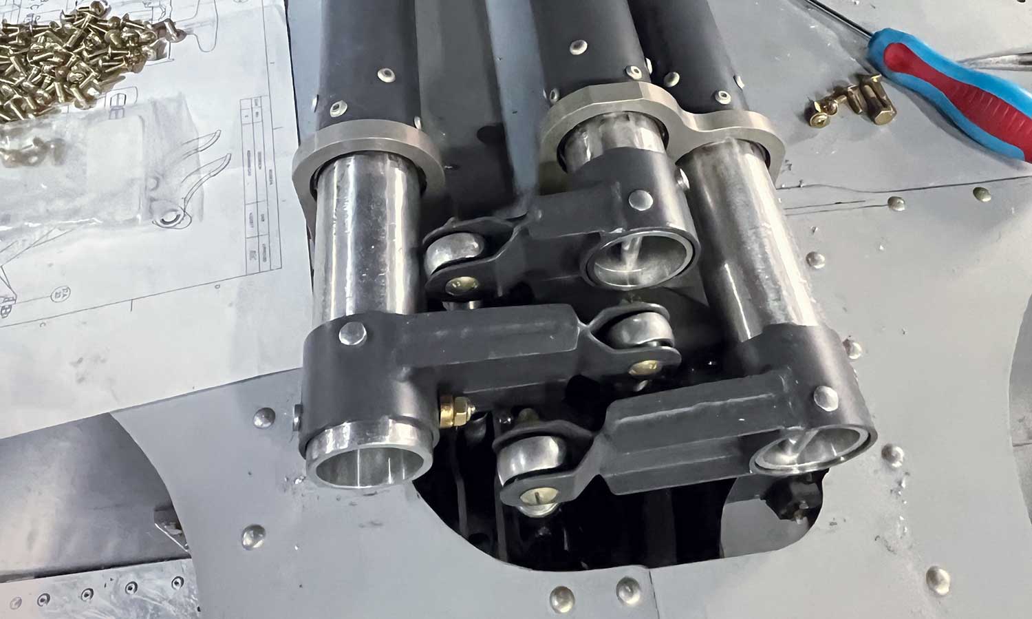
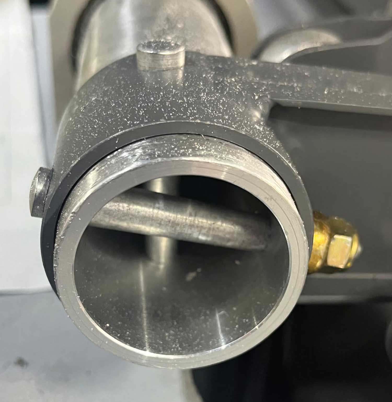
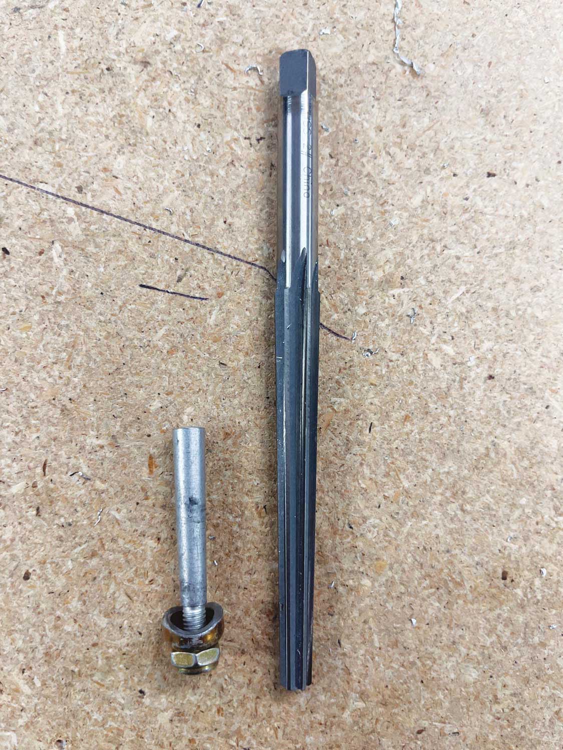
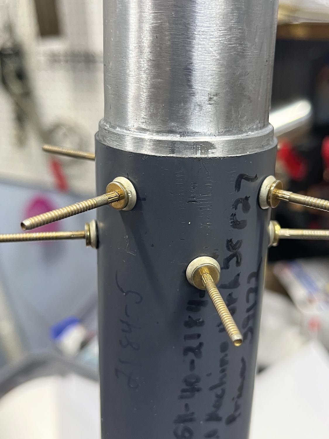
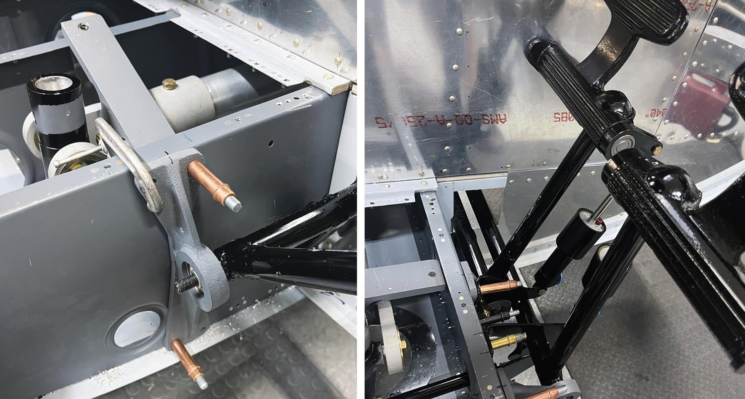
There are three long torque tubes mounted in the aft cabin that are a part of the pitch, roll and azimuth controls. It took quite a while to get all of the machined parts fitting properly with each other, verifying the correct lengths, and then adding the control arms to them with the proper angles. Each of the control arms is mounted with tapered pins in order to promote a tight fit without any sloppiness. Every time I think I have all of the tools I need, I find a step requiring another particular tool. In this case, I needed a Brown & Sharpe taper pin reamer, of which I have never used on 11 prior aircraft.
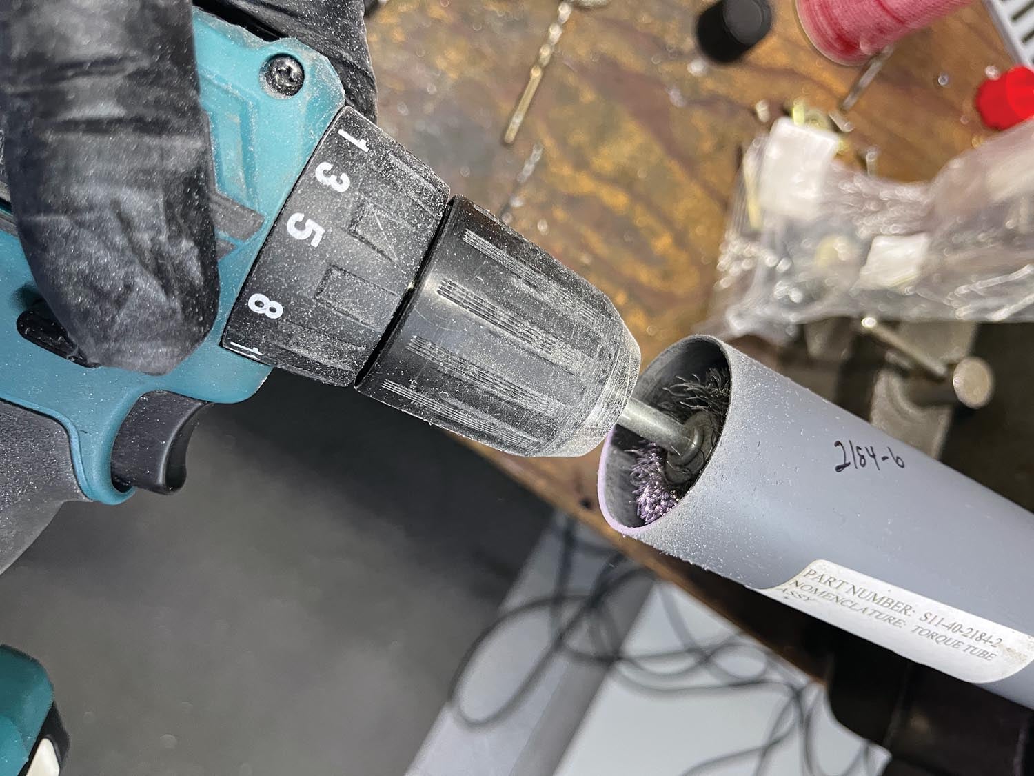
The torque tubes required the end fittings to be riveted on with AN470 rivets. I would love to see the rivet tool they had at the factory for that step, as there was no way I could figure out how to get inside the tube to set the rivets. In the end, with consultation from Brad at Vertical Aviation, it was decided that CherryMAX rivets were an approved substitute.
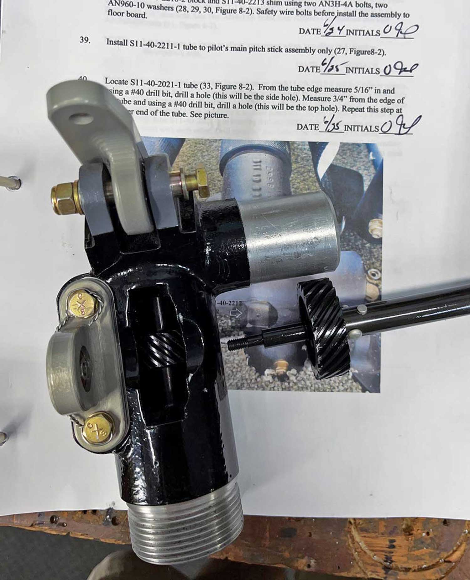
To date, it has been a matter of getting all the control system infrastructure installed. The actual rigging will come after final assembly. Many of the components require some delicate assembly, such as the collective control, as it contains the throttle linkage as well as a shaft connection between the pilot’s and copilot’s respective collectives. It required shimming the gears in the drive shafts to ensure a nice smooth motion between them. Paying attention to detail now will be rewarded with the ability to make smooth minor throttle adjustments, especially while hovering. Just like my Hughes 269C, the Hummingbird does not have an autothrottle, such as on the Robinsons. It has a “correlator,” which somewhat adjusts the throttle as collective is increased or decreased, but otherwise it takes a constant twisting of the throttle to keep the engine rpm in range.
Inside Jobs
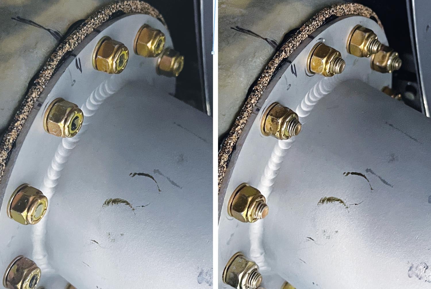
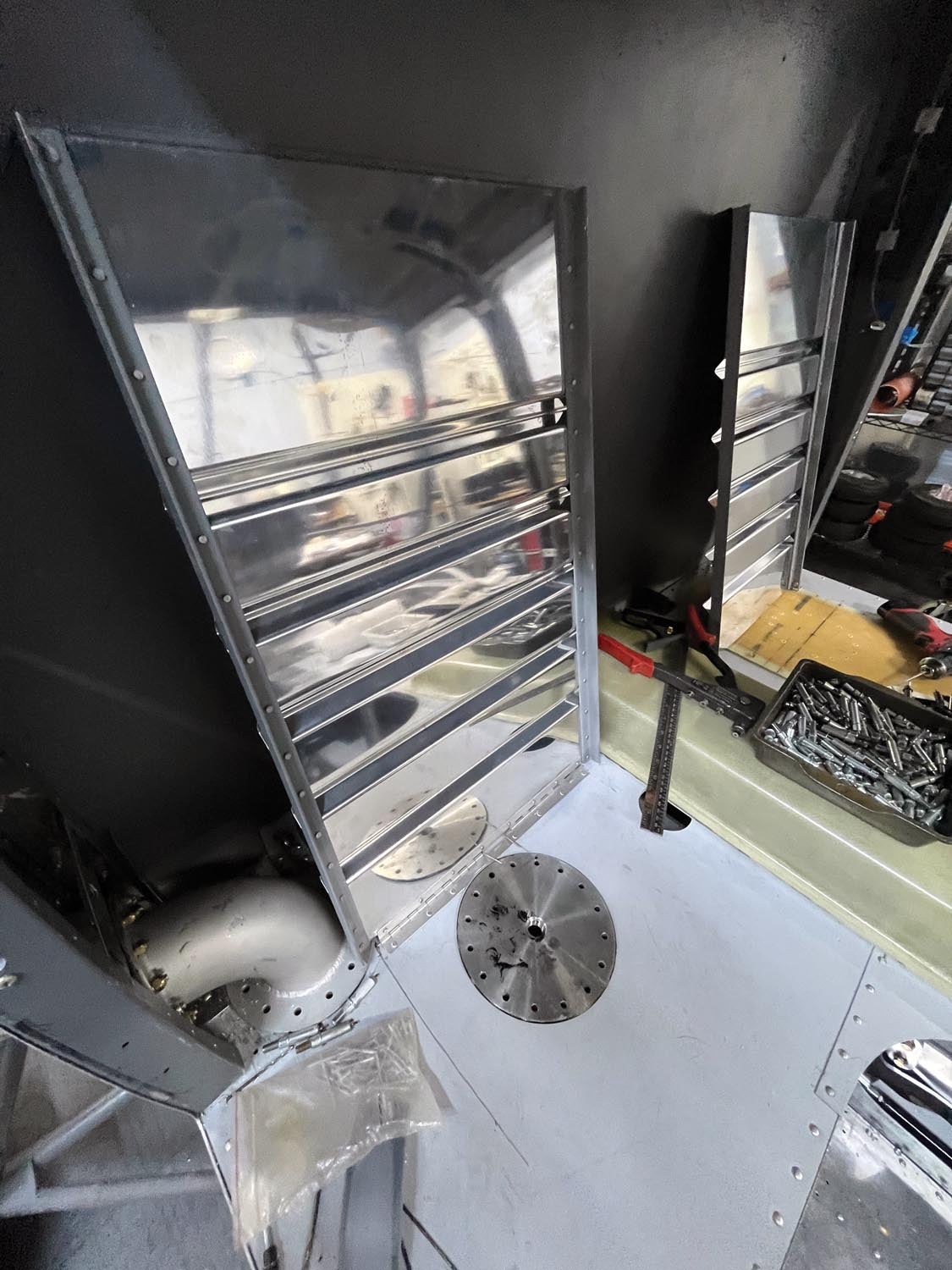
I haven’t painted the interior yet, as I know it will just get banged up installing all the systems, so it is adding an extra step in that they all need to come back out again. To that end, I am trying to pay attention to everything in the interior that needs to be installed prior to paint, even if it isn’t in the proper installation sequence in the manual. For instance, some of the fuel system components protrude into the cabin area, one example being the filler neck for the fuel bladder. The fuel bladder sits underneath the back two seats. While attaching the fuel filler neck to the cabin sidewall, I noticed the AN bolts that were specified were too short, so I replaced them with longer lengths. As a DAR, I often see similar situations where the specified fastener is not the correct length, and I always get the answer that it is what was spec’d or sent. That’s not the right answer, as in real life things come into play such as stacked tolerances, paint, sealants, etc., which can have an impact upon the total thickness of the parts. A rule of thumb on bolts is that there should be 1–3 threads showing, or you should at least be able to catch your fingernail on the bolt protruding past the nut. If there are more than three threads showing, then the next shortest bolt should be used.
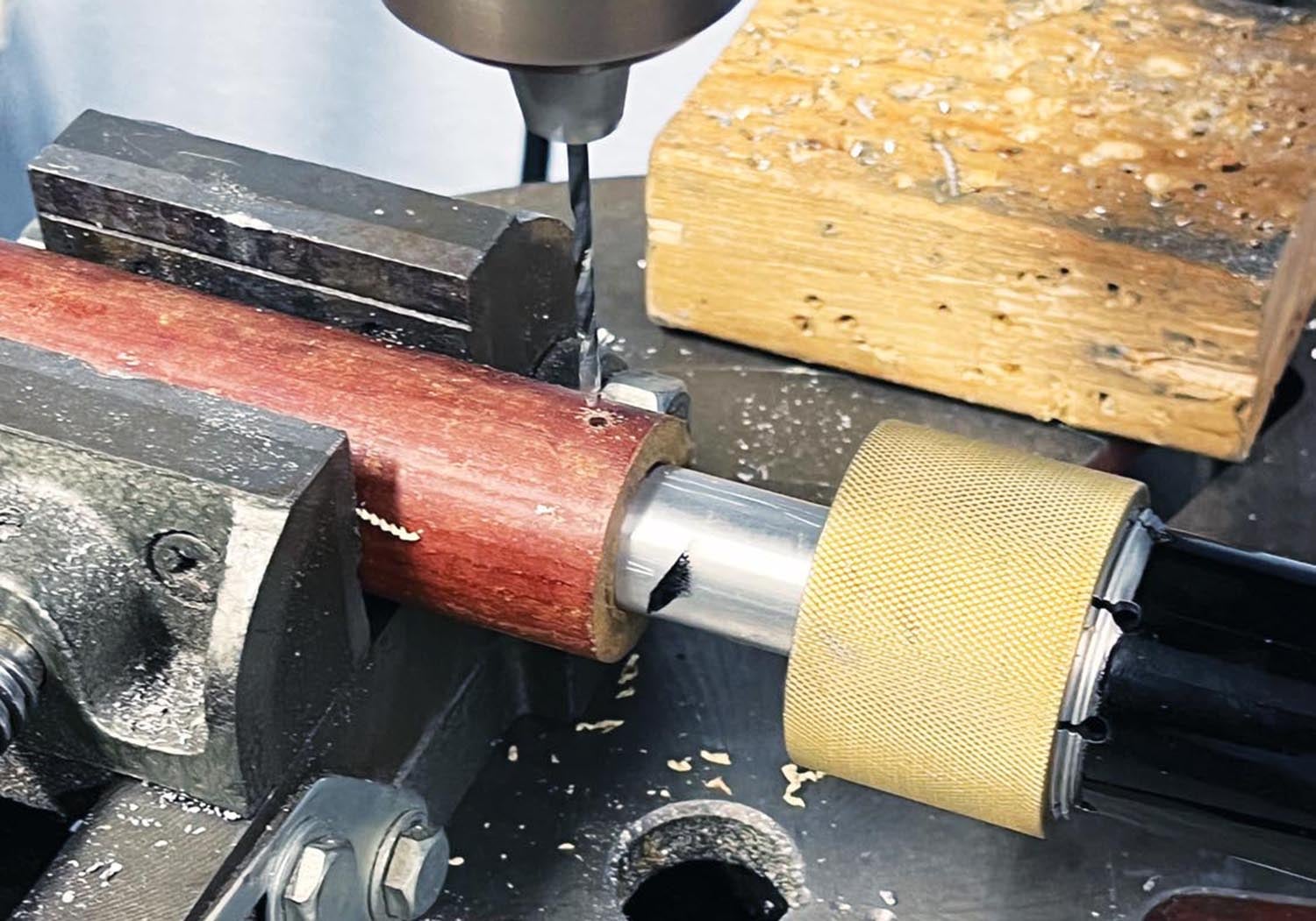
I felt like a one-armed wallpaper hanger installing the brackets and tubes for the anti-torque pedals. It seems like I used every different size of clamps, Clecoes and duct tape while trying to get everything aligned. Remember, this is not a predrilled kit, so when I do drill a hole, I want to make sure it is in the right spot. Working through the tunnel area trying to align brackets on either side of it was a challenge at times. The brackets are sand castings, so the tolerances are a little larger than if they were machined. Consequently, it took a few attempts to get the tubes and brackets in place with enough clearance from each other to preclude any rubbing or interference. I also mounted the pedals to the tubes, as well as the brake master cylinders, to verify the proper geometry and lack of interference.
So far, my only experience with rotor wing aircraft (other than the Hummingbird demo flight), has been on skids. Kind of funny, but when I first started flying helicopters, I couldn’t break the habit of making sure I was stepping on the “brakes” prior to engine start. I honestly think it took me over 20 hours to stop. It will be a different story with the Hummingbird, since it is on wheels. My understanding is that it takes brakes on both start-up and shutdown of the main rotor to stop the torque from turning the aircraft. I’ve decided to add a parking brake.
Another aspect of the interior that’s been on my mind for a while has to do with the rear seats. Quite honestly, the ergonomics seemed like an afterthought, with the seatbacks basically straight up and down against the rear bulkhead. It didn’t seem comfortable to me, and we know passenger comfort can make all the difference when it comes to flying. Then, as I was packing all of the camping gear for OSH into the RV-10, I happened to remove the rear seatbacks, and the light bulb went off! The rear seats of the RV10 are very comfortable, so why not steal a good idea? Sure enough, I built two rear seatbacks à la RV-style (yes, they are pretty much the same seatback in all of the RV models), and I am very happy with the result, especially since I was able to ask Oregon Aero to just build me two RV-10-style rear seat sets. Problem solved!
Pulleys, Pulleys and More Pulleys
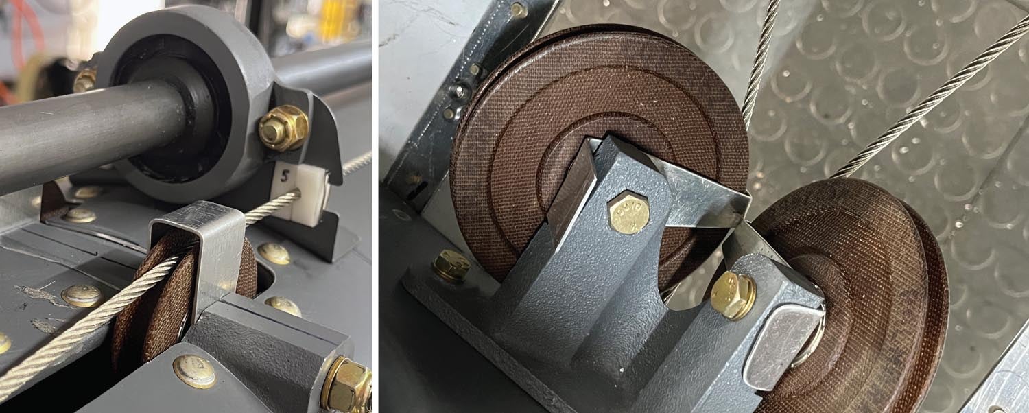
There were six sets of pulleys to be installed. I can’t remember the last time I installed a pulley in an aircraft. Again, there are no predrilled holes, on the aircraft or on the pulley brackets, so alignment is left to the installer. The pulley’s primary job is to properly change the direction of the cable, so it is important to align the cables parallel to the axis of the pulley. A little bit of misalignment can be tolerated, but not much. The AN pulleys are made of a phenolic material, and a misaligned stainless steel cable can wear a groove in the pulley quite rapidly. There is also the requirement for a “pulley guard.” Its purpose is to make sure the cable can’t jump off the pulley. My metal brake came in handy again for fabricating the pulley guards, as the tolerance at the outer diameter of the pulley needs to be quite close to the pulley, yet not contacting it. Basically, the gap needs to be less than the diameter of the cable to properly function.
So now I am a little over 800 hours into the project. I am just starting the cowlings, which are big and unwieldy, and not having much fun with them. I have spent some time designing the instrument panel and am looking forward very much to getting that started, as that is the part of aircraft building that has the biggest fun factor for me. Especially since I enjoy the equipment from Advanced Flight Systems. I think the new AF-6600 screens they introduced at OSH are going to be super-functional in the Hummingbird.


