 Builder’s block. We’ve all experienced it at one time or another. It can come from small roadblocks with specific tasks the builder is uncomfortable with or hasn’t experienced before. But it can also come from tasks such as electrical wiring, engine installation and fuel system plumbing. (Especially if the factory guidance is slight or nonexistent.) It can also be a whole range of other things like finances, health or even waiting on kit components and parts. Builder’s block also appears with weather extremes, which can have a pretty significant effect on the desire to build.
Overcoming builder’s block can be a challenge, too. It is always best to develop a routine and stick to it. Making some kind of progress every day really helps; even when it seems like it is not even enough to matter, it could be enough to keep your mind engaged and thinking optimistically about the project.
With the life changes that were covered in the last article, my builder’s block happened while finding a new “normal.” However, even while adapting to a new normal, I am always thinking about and planning the next steps. This leads me to a quote that always stands out in my mind: If you are failing to plan, you are planning to fail. Plans can change dramatically and quickly, but our mindset in overcoming challenges and continuing to stay persistent is what makes airplanes get finished and flying.
Spring on the Way
On the Humberd Farm, we are finishing up the calving season and the winter feeding season for all the cattle. Of course, the warmer spring weather brings on a whole new set of responsibilities on the farm and also with my work as an outside consultant. There have definitely been some life challenges over the past year, but I’m happy to report that there has also been some good 750SDX progress happening again here in the Humberd Farm shop.
As mentioned in previous parts of this build series, I have a lot of things in the works that I am excited about and I will discuss all of them at length in the coming months. Lately I have dedicated almost all my planning and researching into making this ULPower 520T breathe nicely, both on the intake and the exhaust side. I have a couple of leads for having a custom intercooler built, but I am struggling a bit with the mounting location and routing of the piping/ducting for this unique intake system. I know exactly where I want to mount an intercooler, but clearance issues are showing up everywhere with my custom-built short engine mount and I am slowly working past the conflicts with the throttle cable routing and upper cowl planning.
This leads to a lot of time spent pondering how to best make everything fit nicely. As I sit in the pilot seat looking at a cardboard box (used to visualize the intercooler location) sitting on top of the engine mount, I am considering if it will block forward visibility. While I go back and forth pondering this component, I am also ready to make the other end of the engine’s breathing a priority.
Exhausting Work
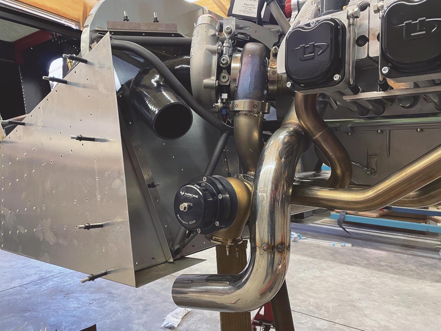
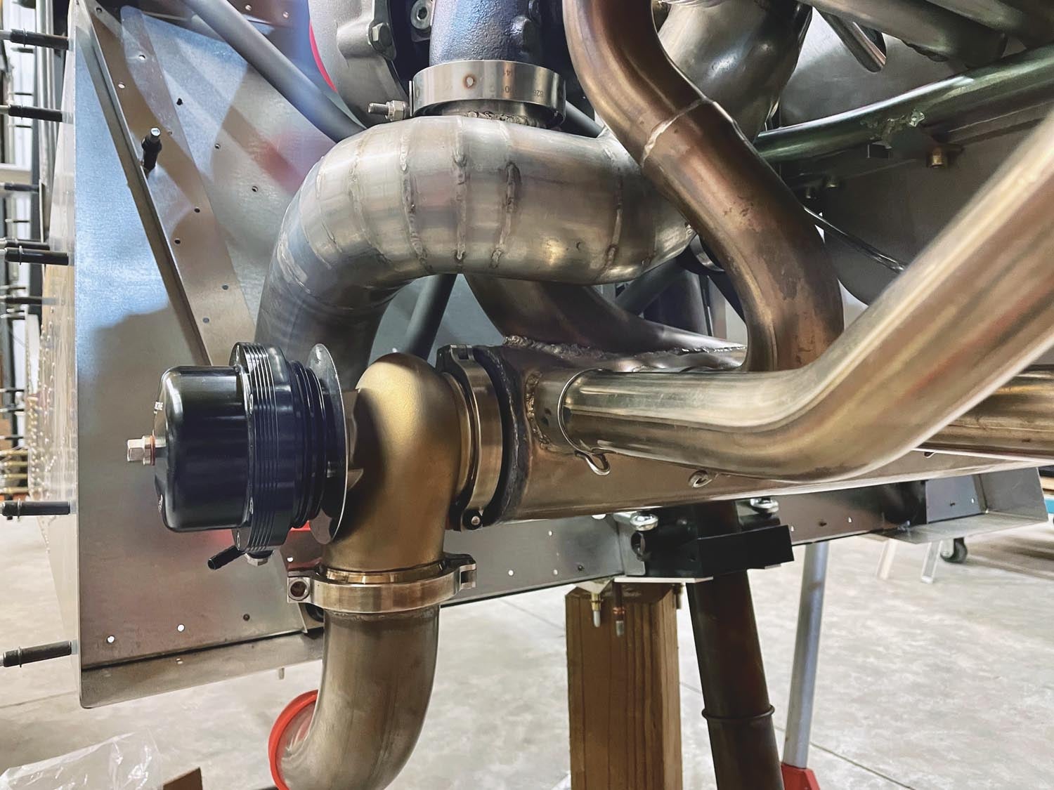
I have been working around both sides of the firewall for quite a while and now that the custom engine mount is complete, I have been looking at some pretty major exhaust modifications. The standard exhaust system for the ULPower 520T comes with the turbo mounted on the right side of the engine and the wastegate mounted on the left side. It makes a really nice dual exhaust setup and should work well as designed and built by ULPower. However, after talking with ULPower on several occasions and getting their approval for building a customized exhaust, it is time to start cutting, fitting and welding on the already beautiful exhaust system of the 520T engine.
There are multiple reasons for this, with the most obvious one being the clearance issues I have with the short engine mount, causing the wastegate to simply not fit in the stock location on top of the left side of the exhaust collector. It became obvious that it was going to have to be moved. The exhaust pipe from the turbo was also going to require modification because the standard pipe routing along with the short engine mount had the exhaust pipe hitting the firewall.
Along with these fitment issues, there is also a personal preference of having a single exhaust outlet instead of a dual exhaust system. So, with a lot of time spent pondering how to make this happen, I decided to move the wastegate to the right side of the collector and Y it into the exhaust pipe coming from the turbo. Luckily, I already had almost everything I needed to start these modifications, so all I had to do was purchase a 180° mandrel-bent stainless exhaust pipe that I could cut up and fit as needed along with a stainless plate that could be machined to become the new thicker end plate for the collector with an integrated mounting flange for the wastegate.
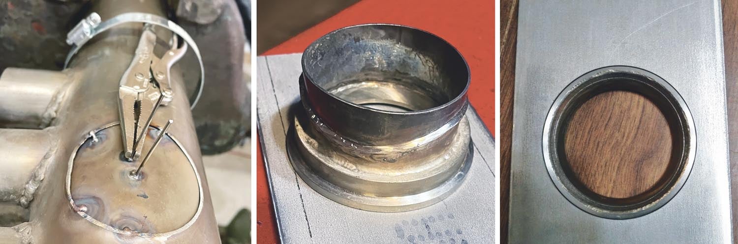
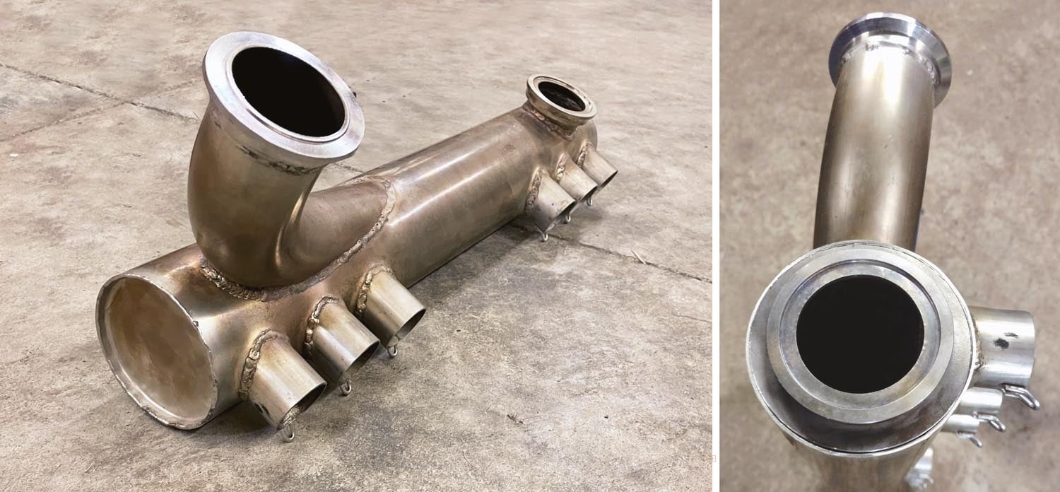
The ULPower 520T comes with V-band flanges welded to the exhaust collector, making the wastegate and turbo connections easy with simple V-band clamps. So the first step was to remove the wastegate and test fit it to check the basic exhaust routing I wanted to achieve. Once I was committed to the changes, I removed the exhaust collector from the header pipe and engine to facilitate the initial cutting and disassembly, then proceeded to cut the stainless flange off of the exhaust collector with an air-powered cutoff tool. I then used a belt sander to grind off the weld and remove the original relatively thin end cap from the turbo side of the collector. The end cap is basically the same thickness as the rest of the exhaust collector, so with these two pieces freshly removed, it made perfect sense to trim the (now scrap) end cap to fit and cover the old wastegate flange hole.
Careful measuring, marking and trimming with a band saw got this piece quickly close to being nearly ready to weld. Just a little bending to match the curvature of the collector and then using the belt sander to clean up the edges, I had the patch ready to be installed. I opted to install the patch on the inside of the collector and weld from the outside. I’m not a master welder by any means, but I have been doing some TIG welding off and on for around 30 years. This particular weld needs to be very professional and without impurities that could cause leaks because I plan to cover it later with a heater muff for cabin heat. A good weld here is imperative to keep the exhaust and CO out of the cabin. Luckily this grade of stainless is fairly easy to TIG weld and I feel confident with the result.
The next step was to take the purchased 1/8-inch-thick stainless plate to have it machined to fit both inside the round collector and also machine the inside to prepare it for welding in the wastegate flange. Basically, the rectangular plate had to be machined into a big stainless washer. While this was being turned in a lathe, I also had the removed flange cleaned up and fitted to weld into the new exhaust collector end cap. To keep things fitting snug, I removed about ½ inch off the right side of the collector and fit the flange as tightly as possible to the end cap, while making sure there was enough room to be able to install the V-band clamp onto the flange. I first welded the flange from the inside of the new thicker end cap and then welded this end cap/flange assembly into the open end of the exhaust collector. Things were looking good and it brings some nice satisfaction and anticipation for the end result when you start seeing this type of modification show some progress with the way you envisioned it.
Easy to Hard
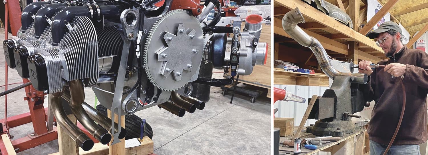
Well, I hate to say it, but that was the easy part of the exhaust modification. Next up is reworking the outlet exhaust pipes and creating a merge for the turbo and wastegate to exit in the same single pipe. Now, with the wastegate mounted in its new location, it is time to start cutting exhaust pipes and fabricating the new exhaust routing. While this may not seem like a big deal, it can be time-consuming to cut, trim and fit these pieces together nicely and make them look like a professional or factory-designed installation.
I have created a few exhaust systems for farm equipment and hot rods, so making this work was not my first rodeo—the last custom exhaust I built was for a high-performance 429 V-8. It had some of the same requirements with space constraints causing issues. There are potentially a lot of power gains to be had by port-matching the exhaust to the heads and creating smooth curves and merges in the system. Luckily, I am not changing any of the header pipes or the basic dynamics of the ULPower exhaust system. A little bit of calculating for flow requirements to be sure the single outlet pipe would be adequately sized was all that was needed before I began the modification.
I honestly don’t expect to see any performance gains here, and the modification mostly boils down to space constraints and personal preference. The only other benefits I hope to achieve with this modification are a potentially unique sound and losing just a tiny bit of weight by having only one outlet pipe instead of two. I have no idea what it will sound like, but having the two different exhaust sounds (one through the turbo and one directly from the collector) merging together should create a slightly different harmonic and sound.
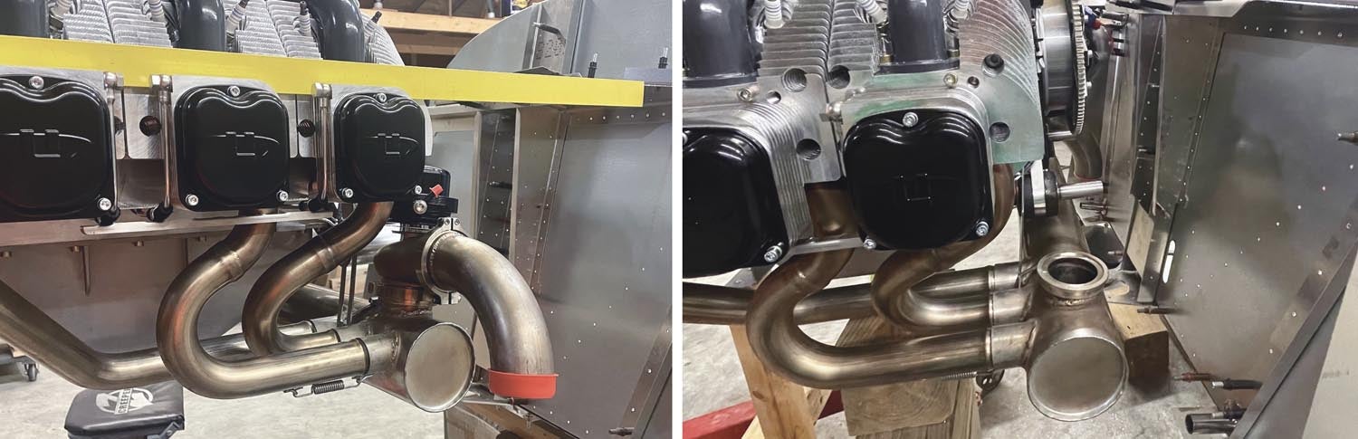
Fitting up straight pipes is a fairly easy process and follows the same basics as coping the chrome-moly tubing for the engine mount, which was discussed at length in the December 2023 issue. The first two pieces were relatively simple and straightforward, with the pipe routing away from the turbo and down in front of the new wastegate location instead of turning rearward and above it.
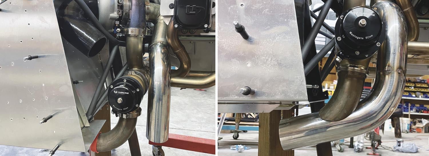
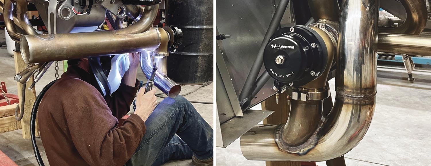
There was still a lot of careful planning and cutting/trimming to ensure the pipes fit together cleanly and with shallow turns. The first pipe cuts were made carefully in a band saw, then they were sanded to a squared edge with the wide belt sander. Once the first three pieces were fit up, I secured them and TIG welded the joints. The next piece of the puzzle was cutting the 90° pipe from the wastegate and trimming it to fit, creating a nice merge. This piece took a lot of time to fit up nicely. I have not found a good way to mock up a 90° curved pipe and join it at the edge of a 90° curve in another larger pipe, while also being slightly offset, so this joint required a lot of installing, marking, removing and trimming to achieve the weirdly shaped contour. I literally repeated those last steps dozens of times to get a nicely matched joint that was ready to weld.
One of my biggest concerns with this last weld joint was that the stainless might expand/shrink in an unexpected way when welding and cause some misalignment or stress issues when tightened down to both the turbo and the wastegate V-band flanges. I tried to secure it by tack welding this joint in six points before welding it all the way around and I was lucky.
I think the result came out well, and I have high expectations that it will work as good as it looks. There is only one final piece I need to add to the end of the tailpipe and that is a curved pipe to turn the exhaust down and away from the lower fuselage. Fitting this last pipe should be fairly simple, but I will wait until the cowl is built and installed to be sure everything fits and works nicely together with no clearance issues.
I know this may not seem like a lot of progress to some builders, but it is still progress and one step closer to a finished airplane. Now that this phase of the build is at a stopping point, it is time to move on to the next pieces of the puzzle. Many of you know that my goal and mission at this point is to create one of the absolute best power-to-weight ratio Zenith 750 SDs out there, without giving up any capacity or usefulness. Since I have had the amazing blessing to be able to hang out with and fly with some of the best STOL pilots and builders in the industry, this has also given me the opportunity to absorb some knowledge and learn a few things from the best. One fun piece of logic that always comes to mind: “If you are thinking about installing something in an airplane and can’t decide if it is worth it, hold that piece about waist high and let go of it. If it hits the ground, it is too heavy to install in your airplane!”
With that being said, I am constantly looking for ways to do things and install components as lightly as possible. I want it to be a capable aircraft, but I really don’t want to add anything that I won’t need or find useful in this 750 SDXtreme.
![Coming in for a landing at Humberd’s Farm [All Images Credited to Jon Humberd]](https://www.kitplanes.com/wp-content/uploads/2026/07/9-1.jpg?w=218&h=150&crop=1 "Overcoming Setbacks on the Zenith 750SD Xtreme")
![[Credit: Zenith Aircraft Company]](https://www.kitplanes.com/wp-content/uploads/2026/06/31142685469.jpg?w=218&h=150&crop=1 "Zenith Throws Open Its Doors for “Fly-In to Summer”")
![Members of the North Idaho High School Aerospace Program gathered at KSZT [Credit: North Idaho High School Aerospace Program]](https://www.kitplanes.com/wp-content/uploads/2026/02/IMG_3499.jpg?w=218&h=150&crop=1 "North Idaho High School Student ACES Fly the Aircraft They Built")


Nice work Jon…keep at it!
Hi John, looks really good. You mentioned about professional look without any restrictions and I hope you know or found out that if you want a good weld in stainless you MUST back purge the inside of the pipe with your shield gas. I have been making stainless exhaust systems for a few years and if you don’t think it is necessary, weld to pieces of scrap together so you can see the inside. It will be a terrible weld on the inside.
To do that on my welding gas supply I bought a y fitting from the weld supply store and attached a house that I use to fill the inside of the piece being welded and let it flow for a minute or two so it fills the inside of the pipe. I have been using Argon for my shield gas.
Ed
Comments are closed.