Building an airplane should be mostly fun, sometimes challenging, and infinitely rewarding, but confidence killers lurk everywhere. For instance, peruse metal-forming websites and textbooks and you’ll encounter the terms K-factor, neutral axis, bend deduction, flat-blank calculation, and mold point. You’ll also be exposed to the equation for developed width—an equation whose mere appearance on this page would have caused you to skip this article.
Want more proof you’re too mortal to make parts from metal? Browse the newly illustrated 2018 edition of Aviation Maintenance Technician Handbook-Airframe, Volume 1, where this sentence, on page 4-67, waits to seduce you: “The J-chart, often found in the SRM, can be used to determine bend deduction or setback and the TDW of a flat pattern layout when the inside bend radius, bend angle, and material thickness are known.”
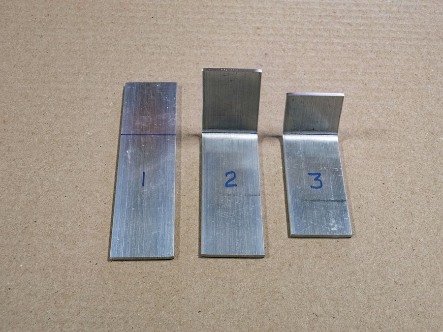
Making accurately bent parts is easy when you start with an oversized blank. Part 1 is a flat, oversized blank with the bend line marked. Part 2 has been bent but is still oversized. Part 3 is the finished part after each leg of the part has been cut to the correct length. (Photo: Kerry Fores)
Every skill (metalworking, woodworking, welding, wiring, painting) has a broad spectrum of attainable knowledge and execution, but kit aircraft builders don’t need to grasp or employ the higher-level engineering knowledge or manufacturing practices used by industry. We’re building airplanes, not space shuttles. While I could provide an example of “unnecessary knowledge” for each skill I’ve listed, I’ll concentrate on flat-pattern layout for bent metal parts, as every airplane I can think of has a few parts made from metal.
The J-chart referenced above simplifies, apparently, calculating the size of the flat blank, or what metal-forming scholars call the developed width, before it is formed into a part. While the J-chart thoughtfully eliminates hideous algebraic formulas, the handbook admits it is “not as accurate” at arriving at the developed width. It proves that assertion with a calculation in which the developed width of an example part works out to 3.965 inches. For those of you doing the conversion in your head, 3.965 inches is a tad over 3247/256 inches, or what I’d refer to as “exactly 4 inches.” I challenge anyone to cut a piece of aluminum 3.965 inches long and then place the bend(s) so precisely that the width of each side of the part is accurate. Further, I challenge anyone to cut a piece of aluminum to 3.965 inches. The good—no, great—news is no one has to. No complicated math is necessary, no J-charts need be consulted, and no embarrassing mention need be made of anyone’s developed width.
Before we continue, one caveat. An unavoidable aspect of forming a part that has two (or more) bends is the need to accurately place each bend in relation to the other bends. A little practice with scrap material and your bending brake and you’ll achieve the necessary accuracy in short order. The layout method described below, however, eliminates the need to accurately place every bend. That results in less material placed in the scrap bin. With that out of the way, let’s move on.
To make a part with one bend—for instance, a .032-inch-thick stiffener with two -inch-wide sides and a 90-degree bend with a 1/16-inch bend radius—you might add the width of each side together to determine the flat blank size. In this example that is 1 inch wide. If you cut the blank exactly 1 inch wide, however, the stiffener will be undersized after you make the 90-degree bend because no material was included to accommodate the bend (that’s called the bend allowance). You could employ the mathematical equation (or the purportedly less accurate J-chart) to calculate the bend allowance whereby, after inputting a K-factor of .33 (don’t ask), you’d arrive at a blank width of 1.1148 inch. That extra .1148 inch will accommodate the bend.
The engineers reading this are checking my math. The faster ones are already composing a letter to the editor correcting my calculation. Some will argue what the correct K-factor is, which underscores the point of this article—it doesn’t matter. But even with a blank cut to the mathematically correct width, the average builder still has to precisely place the bend to achieve two -inch-wide sides. Good luck with that.
The simple approach to making the -inch x -inch stiffener is to cut a blank about 1 inch wide and draw the bend line somewhere in the middle of the blank. “About” and “somewhere,” now those are words a timid builder can embrace. Next, make the 90-degree bend. Finally, trim each side to the -inch width. No complicated math was employed and precise alignment of the part in the bending brake was eliminated. Only a few slivers of aluminum went into the scrap bin. As you become familiar with your bending equipment, you’ll find you can accurately bend the blank so only one leg of the part needs to be trimmed after forming. This technique works for most formed parts including U-channels, hat-channels, seat pans, control surface skins, and drag fittings. It also works for all material thicknesses, from .025-inch-thick firewalls to -inch-thick spar fittings. Don’t forget that, although you don’t have to place the bends accurately in relation to the edges of your blank, you still need to place them accurately relative to each other.
While there are builders who enjoy the deep dive into formulas, theories, and the properties of materials, the kit aircraft industry is, at its heart, a consumer-driven industry. No kit aircraft company wishing to be financially viable would produce a kit that required an engineering degree or a machinist’s knowledge to complete. If you are trying to talk yourself out of the cost and commitment of building an aircraft, by all means continue your research and you’ll quickly find your “out.” But if building an airplane is an inescapable “must” in your life, you’ve already met the most important requirement: desire. The rest is just time and money.







As a long-time aircraft sheet metal mechanic (28 Years) I can say that this is a very practical way to bend metal and the way that I did it for many years. For complex. multiple bends ( U-channels, hat sections, etc) I always bent a test piece and then added or subtracted from my bend lines in order the get the right dimensions on the real piece. Was easy to get +-.030 accuracy this way. I was taught the mathematical way to bend but never got the hang of it. So to do a test piece and then transfer to the real piece always worked for me.