The converted O-290G rebuild is nearly complete (at the time of writing this), so now I need to think about getting it onto our test stand and cranking it. But from whence some spark? I want to run an E-Mag, but I’d like to wait until I’m a little closer to completion before making that purchase and starting a warranty clock ticking. So how about a magneto that can be used for the test runs and later as a backup to the electronic ignition?
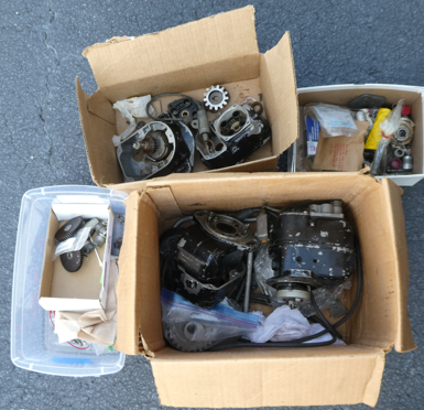
The engine I bought from the chapter came with a couple of mags, plus my original project had a box with several magnetos in it, including one for a six-cylinder (why?) engine. Curiously enough, one of the assorted mags is a Slick that does not fit my engine, and naturally it is the only one that worked when tested. Go figure. That said, no telling when that mag last generated a spark on an engine, so I’m rather amazed that it works at all.
The remaining 4-cylinder mags were in various states of decomposition (for want of a better term) with their coils split open, capacitors leaking, and points corroding. But with some disassembly, it was clear that a couple of them, other than their coils, were in better shape and good rebuild candidates.
Then the questions become: Can I do a rebuild at home? Aren’t magnetos complicated and mysterious? Will the rebuilt mags be airworthy?
Yes, not really, and yes.
The very short version of how mags work is: move a magnet past a coil of wire (or vice versa) and you make some electrical current. In the case of a mag, the spinning magnet energizes a coil that is actually two coils of wire: a primary and a secondary winding. Now open some breaker points, the magnetic field collapses, the electrical current is discharged, and thanks to those two coils the voltage is stepped up to make a very healthy spark. Yes, a very high level explanation.
Those of us of a certain age, or who have vintage cars, will recognize terms like coil, points, and condenser because all cars used to have them and replacing the points and condenser (a capacitor) were part of a yearly tune-up. Why is capacitor called a condenser? According to Prof Google: “In the early days of electricity, scientists like Alessandro Volta used the term “condensatore” (Italian for condenser) to describe devices that stored electrical charge, drawing an analogy to how a steam condenser converts vapor to liquid.” There you go, and you’re welcome for being able to use that bit of bar or hangar trivia when you need it.
The basics of a mag also exist in nearly every small engine, except that breaker points were replaced by solid state electronics years ago. When you pull the rope to start a lawnmower, you are spinning the magnet that is embedded in the flywheel and moving it past the coil. You are, in effect, hand-propping the mower to generate a spark until it starts and runs on its own. Search the interwebs for “Bendix magneto overhaul” and you will find quite a few videos showing mags, their inner workings, and the physics of how they work, including the impulse coupling (more on that later). I’ll leave that as an exercise for the reader. Also online are rebuild manuals for these magnetos; some are new and of fairly high quality, others are older scans of decades old manuals. Obtain all the manuals that you can and familiarize yourself with them.
After quite a bit of reading the manuals, watching videos, and studying the mags on hand, I concluded that I can do this.
For starters (no pun intended), magnetos are dirt simple inside. One of my other hobbies is old hit-n-miss type flywheel engines, and they use magnetos that are very similar to the aircraft mags and often from the same manufacturer. Of note is that the antique engine guys who do magneto overhauls and repairs always have notices that they absolutely will not do aircraft mags. But most the parts inside are similar, if not the same. One of the guys in my chapter says that his dad owned the local feed-n-seed store and would do magneto rebuilds for both tractors and aircraft. And before anyone from the FAA comes asking questions, the guy in the chapter is 80, so I think his dad is well beyond the reach of the law. Just sayin’….
This article is not meant to be a comprehensive how-to, but to share some of what I learned and provide some insights in case you’d like to try it yourself.
After placing an order for an overhaul kit, I completely disassembled one of the better looking mags, while leaving the others in various states of partial disassembly to be used as reference and to compare to the manuals. No, I didn’t mess with the working mag; it will go up for sale.
First some nomenclature: the magnetos in question are both a Bendix S4LN-21. That breaks down to Single type mag, meaning one drive and one set of outputs (as opposed to a single drive gear that turns two mags that are joined together). The “4” for the number of cylinders. “L” for left turning, as viewed when looking at the drive end, which in turn means same direction as the prop when mounted on the back of the engine. “N” for Scintilla design. The “-21” denotes a dog-ear type mount, impulse coupled. Yes, there is the added complexity of this being an impulse mag.
Going back to left vs right-turning. If you are holding the mag in your hands, looking at the gear that protrudes into the accessory case, a left-turning mag will be turning to the left as you are looking at the gear. Which means that it is turning clockwise if you are in the cockpit and behind the engine looking at the mag as mounted to the accessory case. The crank, the cam, and the mags all turn clockwise as viewed from the cockpit, as shown in the gear train diagram from the Lycoming overhaul manual (below).
Thus, if you are looking at the little breaker cam on the end of the armature, it will be turning clockwise. And while we are on the subject of the breaker cam, it has arrows etched into the ends to indicate direction of rotation; which way you mount it onto the armature depends on whether you have a right or left-turning magneto. Check, double-check, and re-check that you have rotations correct as you re-assemble. This is where disassembly photos and the manual are valuable. Note that nearly all mags will be left-turning for most of the Lycoming engines that we homebuilders will be messing with. But still double-check and use the manual.
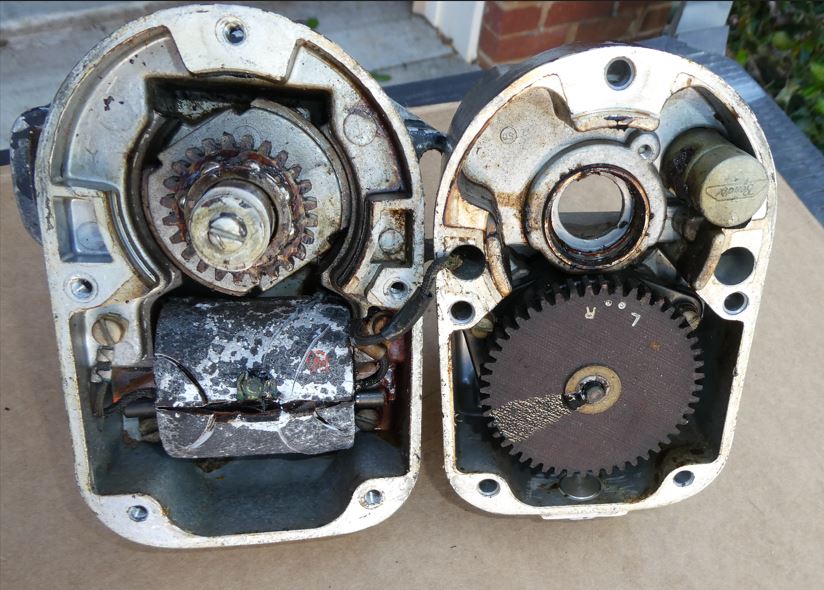
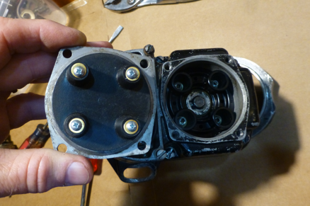
Figure 5 is a photo of one of the mags at the start of disassembly. The photos don’t do justice to the amount of dried grease and goo and dirt inside, nor the smell of said goo, grease, and old, leaking electrics. After pulling everything apart, you end up a collection of parts like Figure 6. Note that there is only one coil per mag; I simply threw in one of the other coils to show two different examples of coil decay. The worst of the collection I labeled as “parts”, meaning that is all it is good for, and even that is questionable. Ick.
The overhaul kit will have a new coil, breaker points, capacitor, ball bearings, and a new gear wheel.
At this time I need to mention the data plate on the mag housing. Besides the previously mentioned model number, there is the part number, something like 10-51360-10. That last dash number is important, especially when ordering parts for your mag. In my case, I saw S4LN-21 in the catalog and ordered a rebuild kit, not paying close attention to the “-10” in the part number, which resulted in a capacitor and breaker points that didn’t fit. No problem, I’ll just swap it out. Oops, the correct kit I needed is out of stock. Fortunately, the critical parts were available individually from Aircraft Spruce and eBay.
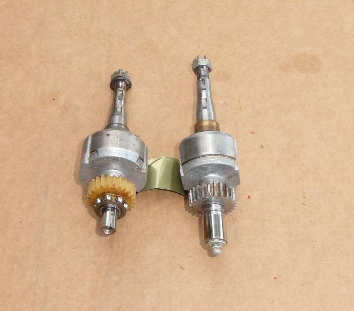
Not readily visible in the photographs is that, on the plastic gear, from the dots for “L” and “R” are arrows pointing to the tooth opposite the dot for the direction of the given mag. The overhauler is instructed to place a dab of red paint on said tooth that is 180-degrees from the appropriate dot. My vintage jar of red Testor’s paint and a toothpick worked great for painting the gear tooth. Why is this not already done for us? Because the same gear is used for both left-turning and right-turning mags, so it is up to you to place the appropriate dab of paint that will later be used for timing purposes. On the older phenolic gears, the arrows don’t exist at all and the overhauler has to resort to a straight-edge through the center of the gear, similar to Figure 8. Life was tougher in the old days.
You’ll need some very fine point snap-ring pliers to remove the gear wheel. I bought an el-cheapo pair and filed the points down a bit until they fit in the snap-ring. The second toughest part of disassembly is removing the flyweights from the main shaft. I managed to make a 3-jaw puller work with some modification, but you really want a 2-jaw puller for this so that you don’t damage the fly-weights. With the 3-jaw puller I used, I not only had to carefully position the jaws, but also had to grind the bottom of the jaws so that they would fit under the impulse coupling cam. I had one cam that came of easily, and two that were quite difficult. The stubborn cams were left with tension on them (for days) with multiple applications of penetrating oil and mineral spirits until they finally released. The manual suggests placing the tip of a heavy duty soldering iron on the cam to help it come loose; apparently my iron is not heavy duty enough. At one point I wrapped the whole assembly in a plastic bag and put it in the freezer (the one in the garage, not the kitchen) for a few hours and then blasted the cam itself with a heat gun with tension on the puller. Still no joy, so I left it for the night with tension on. The next day, the puller was laying over loose and the cam was then easily pulled off.
After disassembly is a lot of cleaning. The upper housing was stripped of parts and put in a parts bath. The lower housing was cleaned with acetone. Use a socket of appropriate diameter to tap out the old oil seal; a rebuild kit will have a new one.
The mag now known as Mag1 (Mag Prime?) has a case that has been thoroughly cleaned and painted to be rebuilt with new OEM internals. The magneto henceforth known as Mag2 will be rebuilt with a new coil, but otherwise with parts salvaged from the on-hand assortment of parts. Before writing any letters, keep in mind that Mag2 has three purposes:
1. For me to practice on before doing Mag1
2. For use on the test stand and on the ground before the electronic ignition is installed in its place
3. To fill that large hole on the right-hand side of the accessory case during #2
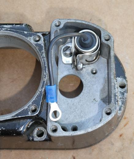
None of the capacitors on-hand tested good, so I needed a new one for Mag2, but didn’t want to spend over $100 for a certified unit. Fortunately, nearly all vintage car condensers have around 0.3 micro-farads of capacitance, same as the ones for the mags, and the same diameter. Which means that a $15 item at the local auto parts store should work just fine. A few minutes to fab an attach bracket, plus crimp an eyelet to the end of the wire, and we’re in business. And lest it vibrate loose, a couple of dabs of epoxy were placed between the capacitor and its bracket.
Why does this work? Because the purpose of the capacitor is to reduce the arcing across the points (which leads to pitting) when they open, and to increase the rate of the collapse of the magnetic field in the coils, making for a hotter spark. And even if the automotive version is off by a few micro-farads, it won’t make a hill of beans difference, as my dad would say. Feel free to disagree, but I’m going to chalk it up to you having a bad Faraday… (Sorry, couldn’t resist).
Getting the spark out
After the spark is generated across the breaker points, how does it get to the spark plugs? Through the distributor block and associated parts. The distributor block is a piece of plastic that has the rotor on one side and brass prongs that take the spark to the other side to the plug wires. The rotor gear spins in an oil-impregnated bronze bushing in the center of the distributor block and takes the current from the coil through a brass arm (the electrode as seen in Figure 16) which sweeps past the previously mentioned prongs.
The procedure for the oil impregnation is to plug the bottom of the bronze bushing, fill it with oil, and bake it at 250 degrees for three to four hours, and as the bushing cools, it draws in the oil. Not wanting to do this in the kitchen, a trip to Wally World was in order for a cheap toaster oven. As for the plug to hold the oil in, a 3/8” dowel was inserted into the bottom of the bushing for a snug fit. Apparently not snug enough, as the oil slowly leaked out and made a mess in the tray, requiring several refills. Note to the reader: obtain the specified plugs; they are cheap from Aircraft Spruce and will allow you to do the job properly and without making a mess. Order them and new snap rings while you are ordering the other overhaul parts. The cams for the breaker points are also baked in oil, but they can be fully immersed, making that a lot easier.
The manual calls for using “magneto oil”, the blend of which I had difficulty determining. Not wanting to spend a small fortune on way more special oil and grease than I would ever need, I went with a synthetic grease for the bearings, and 0-W20 synthetic where oil was called for. I’m sure someone will question this, but synthetics have some amazing lubrication properties, even in less than ideal conditions, and this is for a non-certified application. The block itself is supposed to get a coating of a different special oil while getting baked; not having that special oil, I skipped this step and have not noticed any ill effect. If the little springs in the block get compressed down too much, you can very gently pull them up a bit, but be careful. If you pull the spring out, it is not fun to reinstall without the special tool. Don’t ask me how I know this….
As for the rotor gear and armature teeth, they were sprayed with a coat of dry Teflon-based lube per the manual. The rotor gear retaining clip wants to turn with the rotor and rides on a metal washer; a tiny dab of grease was applied to the washer surface to reduce wear between it and the clip, and allow the rotor to spin more easily. On the other side of that metal washer is a felt washer that is soaked with oil as part of the overall lubrication of the rotating assembly.
The overhaul manual specifies removing the bearing races from the rotating magnet with a special tool. I do not have said tool, but the ball bearings in their cages can be easily slipped onto the armature shaft and seemed to fit quite well into the existing races. With the races thoroughly cleaned, they were left as-is on the rotating magnets. Note that the manual has you dry assemble the case halves and check the bearings for run-out, wobble, and how well the assembly spins. If all checks out, take it all apart, pull the bearings (in their cages) off, lube them with grease, and place in plastic bags until ready for final assembly.
It turns out the manual gives sage advice because while all seems swell for the used bearings on the ground-bound mag, when the case halves were joined, the bearings wanted to push past the worn races on the rotating magnet and then not spin freely. I fabricated a couple of thin aluminum washers to prevent the bearings from pushing downward, installed them with a coating of grease, and pressed onward. Since Mag2 is likely to not get even double-digit run hours, it should be good with the used bearings; Mag1 had new bearings installed and no issues observed during the pre-assembly. As for the points, a new set will go into Mag1 and a cleaned up set of used points in Mag2.
The spark travels from the carbon brush in the center of the rotor out to the rotor electrode where it then jumps the gap to the brass electrodes that go through the rotor block. On the side of the rotor block opposite the rotor gear are the “towers” to the plug wires; between the towers and the rotor block is a molded rubber piece that works as a seal and contains little machine screws. The screws are, no kidding, hardware store screws (#6 IIRC) that rest on the springs on the top side of the rotor block, and on the other side the plug wires jam onto the points of the screws. Nothing fancy, but it works.
Internal Timing
Setting the internal timing is supposed to make use of a special plate with degree markings and a pointer that clips to the end of the breaker cam. Not having said tool, I improvised. My college drafting protractor (required for one of the last analog drafting classes before they all went digital, thank you) was used to make 10, 15, and 25 degree marks on the casing, and a short straight-edge nestled in the screw slot worked as a pointer. With the red mark on the timing gear showing in the case opening, you are to then turn the armature backwards a few degrees until the magnets “pull-in” and hold the armature in a “neutral position”, as the manual describes it. With everything assembled, feeling this neutral position wasn’t quite as easy as with everything dry, but it’s there, and you’ll still be able to see the red gear tooth in the window, albeit off to the side by about one tooth. The pointer tool is then pointed at zero degrees; in my case, I marked a de-facto zero line.
At this point, so to speak, the overhauler is instructed to turn the mag in its normal direction until the pointer is at the ten degree mark and the points are adjusted to just begin opening. Not having the pointer tool, I used my straight-edge to note the nominal zero mark and my handy protractor to show me where +10 degrees was. Nor did I have the timing light tool to determine that the points were just beginning to open, but I did have an old-timers trick from one of the forums: adjust the points just enough that they “turn loose” of a piece of cellophane from a cigarette pack. Having left my ciggies in 1980-never-done-that, I looked around and found a restaurant toothpick still in its cellophane wrapper. Score! The mag is then turned further in its normal direction until the points are at max opening and set to a gap of 0.018 +/- .006 inches. So the purpose of the original cellophane gap setting before that? Beats me, other than determining where the points are just beginning to open. A timing “buzz box” was later employed to set the overall timing once mounted on the engine.


I’m always surprised when someone says they’re going to install “an E-Mag,” meaning only one. First, the advantage of variable spark timing is lost with only one. Second, the E-Mags are not prone to wear, keep their timing, and are just as reliable if not more so. Third, starting is easier because a of standard feature equivalent to a “shower of sparks” magneto with five rapid sparks at starting RPM.
My dual E-Mag preflight checklist includes one additional step that traditional mags don’t require which is to test the internal self-power generator by briefly cutting ship’s power to each eMag, accomplished with two normally-closed pushbutton switches for each mag.
The E-Mag should not be lumped into the sketchy category of other electronic ignition systems because of it’s individual, internal power source that truly duplicates that of a traditional mag.
I had a Piper Arrow that wouldn’t restart after is was warm. Problem was so bad one of my so called friends asked me if I had an electric motor. It went on for years and no one could fix it until it finally gave out one day at another airport. It was fixed the next day. Weak magnets in the (Starting) magneto.
Fixed wing aircraft are antiques. Get an electric vertical takeoff and landing (eVTOL) aircraft. 4 ultralights
are currently on the market: Pivotal Helix, Jetson 1, Skytech, and Yivtol. I believe Skytech offers a two place, but am uncertain. I believe all of these have 3 separate softwares that continually talk to each other to maintain aircraft stability. Plus, LIDAR, for avoiding obstructions: wires, trees, or signs. No need to fly fixed wing aircraft any longer. Join the 21st century and get an eVTOL aircraft. And, with time, one should eventually be able to get a permit from their city to come and go from their private airspace, city lot driveway. And the US Congress may intervene with the FAA to allow flying from driveways; since the airspace above: streets, alleys, boulevards, avenues, and highways, below 1000 feet above ground is unused. Fixed wing mags are a royal pain; meaning forget fixed wing aircraft. The eVTOL revolution is on going. With the above 4 companies selling ultralight eVTOLs, 10,000 could be in the air in the next ten years! Be one of them!
Pretty sure the timing advance of the E-mag will fire the cylinder in advance of the standard fixed timing of a conventional magneto thereby allowing the advantage of variable timing. In this instance the conventional mag is just batting clean-up !
Comments are closed.