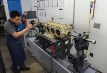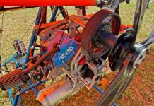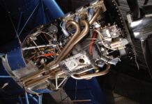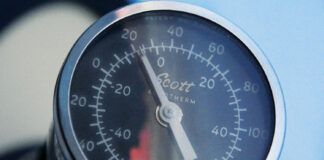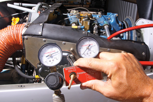
Join us mid stage of the differential compression check. The pigtail is in the spark-plug hole and the inlet side has been pressurized and set to 80 psi. Whats next is to turn the brass valve below and between the gauges to pressurize the engine side. Watch out, if the cylinder isn’t at top-dead center, the prop may rotate; this is a great two-person job.
The health of the top end of our airplane engines depends on the integrity of cylinder assemblies, pistons, intake and exhaust valves, intake and exhaust valve guides, valve seats and spark plugs. Static and dynamic seals control the heat and pressure.
Simply put, static seals are those maintained by the valves, and involve a number of variables including valve head angle and shape-is it round, or something else?-valve seat condition and even valve guide fit-its diameter, concentricity with the valve seat and fit with the valve stem all count. When the static seal between an exhaust valve and the valve seat leaks, the valve gets hot enough to distort and eventually burn. Uncontrolled heat and pressure leak past the valve and break down the lubrication between the valve stem and valve guide, accelerating guide wear, causing further valve-to-seat misalignment and more burning. The cycle accelerates until the valve fails. Leakage past the dynamic seals causes premature lubricating-oil contamination, excessive crankcase pressures and high oil consumption rates.
Static seals also include the threaded joints between the aluminum head and the steel cylinder barrel. The dynamic seals are formed by the hydrodynamic seal between the compression rings on the pistons and the cylinder walls.
The static seals should not leak, but the dynamic seals always leak, and the leak rate varies widely and depends on many variables. The differential compression test (DCT) is the most common method used to determine the health of an engines top end. Borescope inspections, crankcase pressure tests, and fuel and oil consumption trends round out an engine technicians diagnostic tools.
Differential Compression Test
Both Textron Lycoming and Teledyne Continental Motors (TCM) publish service information about compression tests-and they couldn’t be more different.
Heres what they agree on. Both direct users to conduct differential compression tests. A differential compression test requires that compressed air-usually 80 psi-be pumped into each cylinder when the cylinder is at operating temperature and the piston of the cylinder being tested is at top dead center (TDC) on the compression stroke. The supply pressure is read on a gauge. A second gauge is mounted on a common manifold and is separated from the first gauge by an airflow restriction between the two gauges. Lets call the two gauges the supply gauge and the cylinder gauge.
During the actual testing, one spark plug is removed from each cylinder. Then a screw-in adapter with a quick disconnect fitting is screwed into the spark plug hole. A flexible hose connected to the cylinder gauge side of the manifold is connected to the quick-disconnect, and the supply pressure is set at 80 psi.
The cylinder gauge indicates-in psi relative to the supply air pressure-the amount of leakage past the seals of the cylinder being tested. Technicians write compression readings in a leakage over supply shorthand (e.g., 65/80).
The type and location of the leakage is determined by listening. Static-seal leaks past the exhaust valve are detected by listening at the exit of the exhaust pipe, intake valve leaks by listening at the inlet air filter, dynamic seal leaks by putting an ear to the crankcase oil filler tube.
TCM publications direct users to calibrate their differential compression testers before every compression test; Lycoming doesn’t mention tester calibration at all.
Lycoming Says…
Lycoming, in its two-page Service Instruction (SI) 1191A, simply says, If the pressure readings for all cylinders is equal and above 70 psi, the engine is satisfactory. It goes on to say that if pressure readings drop below 65 psi, wear has occurred and subsequent compression checks should be made at 100-hour intervals to determine the rate of wear. Lastly, it says any time readings drop below 60 or if wear rate increases rapidly, cylinder removal and overhaul should be considered.
Lycoming wants the cylinder readings to match up closely. SI 1191A also says, Pressure readings for all cylinders should be nearly equal; a difference of 5 psi is satisfactory; a difference of 10 to 15 psi indicates an investigation should be made.
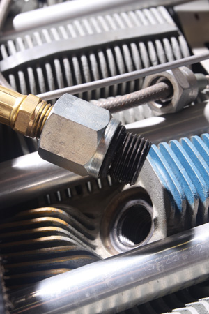
The adapter screws into the spark plug hole. There’s no need to make it more than hand tight; the O-ring does all the work.
TCM Expands on the Subject
TCMs 14-page Service Bulletin (SB) 03-3, explains that compression testers need to be calibrated before every test using something called the master orifice. The reason? In the early 1980s, TCM found that too many perfectly good cylinders were being removed for low compression readings. After extensive testing on how cylinder compression affects engine power, TCM wrote a bulletin (M85-15: superseded by SB 03-3) of definitive guidelines outlining compression testing procedures for TCM cylinders.
Curious about what they found? Read the following statement printed in TCMs Tips on Engine Care booklet: Engine testing has shown that certification horsepower ratings will continue to be delivered even when all cylinders are at or below the minimum allowable calibrated compression reading as established by the master orifice tool.
Compression gauge tools are calibrated by attaching a special orifice tool to an existing gauge set, or by purchasing a gauge set that has a built-in testing orifice included. The calibration step establishes what Teledyne Continental calls the minimum acceptable pressure leakage limit (MAPLL). Many maintenance technicians now list the MAPLL for the compression gauge set used when recording compression readings following compression testing.
Gauge readings alone don’t tell enough about a cylinders airworthiness, because compression is only one part of the puzzle. So don’t pull a TCM cylinder for low compression unless additional tests reveal that the cylinder is worn or leakage at a valve has gotten so bad that the valve is showing signs of distress. The only way to visually check the condition of the valves and the cylinder walls is with a borescope. TCMs SB requires a borescope inspection be done in conjunction with every compression test.
Low Compression?
TCMs detailed SB is full of information that stomps old school protocol flat. Airframe and Powerplant (A&P) Technician schools study an FAA publication titled Aircraft Inspection, Repair and Alterations, Acceptable Methods, Techniques and Practices. This weighty tome is also known as Advisory Circular (AC) 43.13-1B. It says, A loss in excess of 25 percent of the input air pressure is cause to suspect the cylinder of being defective. Thats the old standard. TCM wants cylinder removal decisions to be based on at least two calibrated compression test results, a borescope inspection, oil usage determinations and crankcase pressure readings. After a low compression reading, the airplane should be flown for an hour at cruise power settings and tested again.
One test is all thats required for a few defects. For instance, if air can be heard rushing (not whistling, but rushing) past an exhaust valve, and the borescope inspection shows localized discoloration on the valve face, or if a piece of the valve is missing, then the cylinder must be removed. If there’s a crack at the spark plug spot face, or if there’s an air leak at the cylinder head-to-barrel junction, the cylinder must be removed.
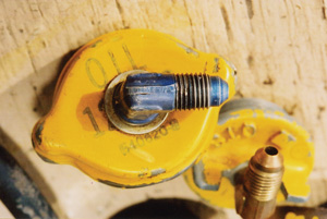
Your local shop probably has a selection of oil-filler caps set up with hose fittings. See if you can borrow one before making the piece yourself.
The Borescope Inspection
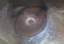
A borescope is a tool with a lighted, magnifying lens on the end of a narrow rod thats small enough to insert into the cylinder through either spark plug hole. This tool allows technicians to take a look at the inside of each cylinder. Visual inspections reveal faults such as material erosion of the piston crown or of the valves or valve seats, cracks on the exhaust valve face, cylinder wall corrosion, cylinder wall scoring due to piston rub, smeared aluminum deposited on the cylinder walls due to piston pin plug rub, and excessive oil and heavy carbon deposits, all of which compromise engine operation and none of which are detectable during a differential compression test.
Exhaust valves are exposed to brutally high temperatures. In Lycoming designs, valve temperatures are controlled by a path that carries the heat up the stem and out to the valve guides and on to heads-the result of the use of hollow-stem exhaust valves filled with sodium. In use, the sodium liquefies and helps transfer heat from the head of the valve, up the stem and out through the guide.
TCM valve temperatures are controlled by a path that transfers heat from the head of the valve to the valve seat through contact. When a TCM exhaust valve isn’t making good contact with the seat, the heat transfer is compromised, and that portion that doesn’t have good contact will be hotter than the rest of the valve. This causes a discoloration at some point on the valve circumference thats easy to see. In almost all cases, this discoloration will appear before the valve-to-seat seal fails enough to cause a sharp drop in compression readings. Regular borescope inspections catch valve-sealing defects early in the damage cycle.
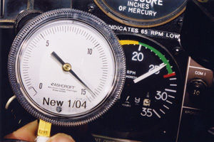
Crankcase pressure testing requires plumbing a low-pressure gauge or an airspeed indicator into the oil-filler tube and reading the pressure against engine speed.
Crankcase Pressure Testing
When an engine uses a significant amount of oil, blows a lot of oil out the crankcase breather tube, and the oil darkens very quickly (within 5 to 10 hours) after an oil change, its a sure sign that the dynamic seal between the compression rings and the cylinder walls is bad and combustion byproducts are escaping into the crankcase past the rings. In most cases, the compression readings will still be respectable.
Crankcase pressure testing is a quantitative method for determining the health of the dynamic seal, which is affected by cylinder wall wear, piston wear including piston ring groove wear, and ring wear or loss of temper. Crankcase pressure testing is detailed in TCM SB M89-9.
The easiest way to do this test is to buy a replacement oil filler tube cap and install a fitting so that a hose can be connected. Install the modified cap, connect a hose and run the other end of the hose to an airspeed meter. Its OK to make the hose lengthy enough to run it into the cabin during testing. After warming up the engine, run it up to full power briefly and note the meter reading.
According to M89-9, the limit is 38.2 knots (44 mph or 1 inch of H₂O) for A-65, C-75, C-85, C-90, O-200, C-145, O-300, GO-300 and IO-346 engines. The maximum permitted for TCM large bore engine is 78.2 knots (90 mph or 4 inches of H₂O). These engines include the IO-360, TSIO-360, O-470, IO-470, TSIO-470, IO-520, TSIO-520, GTSIO-520, 6-285 and IO-550 models.
If the crankcase pressure reading is too high, the crankcase breather tube may be blocked. Some air-oil separators can also increase crankcase pressures. Disconnect these from the engine and test again. If pressures come down, the breather tube or air oil separator or a component of those systems is faulty. If the pressure is still high after the systems are disconnected, the dynamic seal between the rings and cylinder walls has been compromised-cylinder removal and rework are the only remedy.
Complete Testing
Comprehensive top end health diagnoses require periodic differential compression tests, borescope inspections and crankcase pressure tests. There will always be some variances in compression values and crankcase pressure readings, so don’t worry if these values fluctuate a little. Just get out the borescope and look inside your cylinders-you’ll see trouble almost before it starts.

![]()
Steve Ells is what you call a gen-u-ine mechanic, a bonafide A&P with an Inspection Authorization. Former West Coast editor for AOPA Pilot and tech guy for the Cessna Pilots Association, Ells has flown and wrenched on a wide range of aircraft. He owns and wrenches (a lot!) on a classic Piper Comanche. But don’t hold that against him.

