Change being inevitable, the editor in chief has declared I should write a series on engine anatomy for those moderns deprived of shop class and robbed of self-realization by all the plastic shrouding under modern car hoods. You’ve been warned.
This being a multi-article enterprise, let’s define the objective as introducing piston engine fundamentals to you, the aviation experimentalist. This will be more lecture hall than lab work, with hope that a better understanding of the why of piston engines will aid you in the how of their selection, installation, and upkeep.
Pumping Air
Before getting into why all the Lycoming, Continental, and Rotax engines are horizontally opposed, let’s start at the beginning to establish that piston engines are air pumps. Their working fluid is air, which is aspirated into a closed cylinder, expanded many times to increase its pressure and thus push the piston into doing some work such as turning a propeller. Expanding the air is the only reason we add fuel and then set it on fire—simply to heat and thus expand the air.
Remember that breathing—the ability of an engine to inhale and exhale air—is a fundamental function driving its ability to do work. The other basic is how well the engine expands the air it breathes. More air mass and more expansion mean more power. It also follows that it takes fuel to make power; how much fuel an engine uses is a surprisingly useful rule of thumb to how much power it is making.
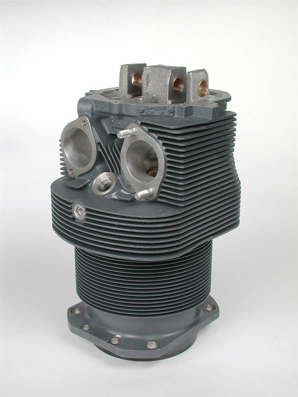
Engine design begins with the cylinder because it’s where the airflow meets combustion. Once the cylinder is designed, such as this Lycoming 360/540 parallel valve unit, the rest is selecting the number of cylinders, their mechanical arrangement, and providing the resulting breathing, lubrication, cooling, and other systems.
The Cylinder
It’s useful to consider an aircraft engine as a collection of cylinders flying in formation. The cylinder is the basic unit of engine design; it’s where the engineer makes his first sketches—and compromises.
A primary selection is how large to make the cylinder. Larger cylinders—greater diameter, piston stroke, or both—make more power, but when all the physics are considered, one huge cylinder doesn’t cut it. Scaling up an .049 Cox Thimble Drone to lift an RV-10 would lead to teeth-buzzing balance issues, horrible friction, tremendous fuel waste, and be rather difficult to prop start.
Furthermore, because general aviation engines have little need to turn high rpm as we’ll see, it’s less expensive and less weight to use fewer, larger cylinders than in a car. Lycoming’s ubiquitous O-360/540 cylinder (the O-360 uses four and the O-540 six of the same cylinder) displaces a voluminous 90 cubic inches. That’s 1474 cubic centimeters (1.5 liters) or roughly the displacement of an entire air-cooled VW engine per cylinder! A comparable 360-cubic-inch automotive engine would turn higher rpm and use eight cylinders.
One upper limit on cylinder diameter is the time necessary for the combustion flame front to travel across the bore. In practice 6 inches is the limit at any conventional engine rpm and piston stroke, and this is with two spark plugs mounted across from each other. Single-plug combustion chambers must be smaller, one reason auto-engine cylinders rarely exceed 4.5 inches. Still, large-bore cylinders have strong advantages, mainly in allowing larger valves and letting those valves breath better because they aren’t shrouded by narrow cylinder walls.
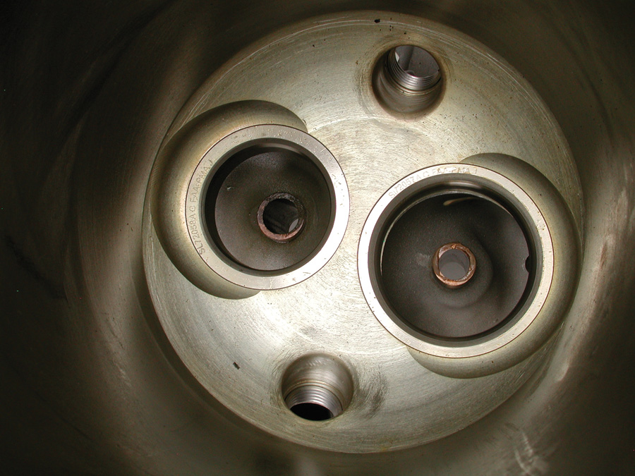
We find much of the bellyaching in hangar flying bull sessions regarding “ancient” engine technology a little over-blown, but we must say there is room for improvement in combustion chamber design. At least the two spark plugs are widely spaced (at 1 and 7 o’clock in this photo); that and superior gasoline have helped these large, sort of lazy airflow chambers get by for decades.
Speaking of which, our engineer definitely establishes the basics of cylinder breathing. Traditionally this is accomplished via two relatively large poppet valves: one each intake and exhaust. Four smaller valves—two intake and two exhaust—package a considerably larger “window” of valve area in a given size cylinder, and in many modern car engines this provides superior breathing. It also worked in old car engines—one of the first four-valves was the dominant 1912 Peugeot grand prix car—and high-achieving aircraft engines such as the Allison and Rolls-Royce V-12s of WW-II fame were four-valve designs. But four valves cost more than two valves, and it’s certainly less expensive initially—if perhaps not as efficient in the long run—to make a slightly larger displacement cylinder to obtain the same power.
Somewhat related to the number of valves is the shape of the combustion chamber formed by the cylinder head and top of the piston. The short story here is legacy Continental and Lycoming chambers are open as barns and out of date as omni navigation, while the Rotax offers a more advanced quench-type chamber. It’s the same story with the intake and exhaust ports.
Another basic is how fast the cylinder will operate, that is, what is the engine’s rpm range. Consider the primary reason to have a piston engine in a plane is to turn a propeller (thrust is what we’re really after), so accommodating the propeller’s needs is smart policy. And it turns out propeller efficiency is best at very low rpm, so unless the daunting engineering, cost, and weight of a prop speed reduction unit are deemed unavoidable, low engine rpm is advantageous. Friction from the bearings, piston rings, and so on are all reduced in low-rpm engines as well. Most practically that’s a boon to fuel economy, but it also means less heat rejection is necessary.
Duty cycle is another fundamental driving aircraft engine design. The term is engineer-speak for what percentage of time the engine spends producing maximum power. For example, auto engines are sprinters, rarely asked to put out max power and spending well over 95% of their life loafing around 30% of their maximum capability. Aviation engines are more akin to marine engines, where relatively short periods of maximum effort are followed by endless hours at a high percentage of maximum power. The familiar 75% power setting comes to mind. So, while checking weight growth always hangs over the engine designer, robustness of what he does put in the engine is a necessity.
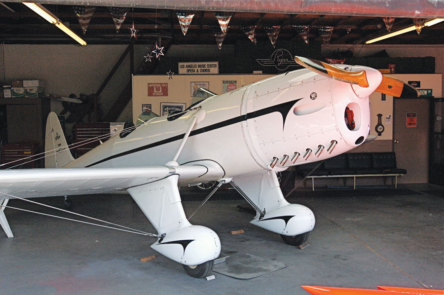
Inverted inlines fit aircraft well. Their narrow frontal area is inherently aerodynamic, and putting the crankshaft at the top of the fuselage gives the propeller maximum possible clearance. Originally fitted with a four-cylinder inverted Menasco inline, this Ryan now wears a six-cylinder inverted Ranger.
L, V, W and X’s
As the designer begins to arrange his cylinders into an engine he is confronted with more realities and endless compromises. Above all an aircraft engine must be reliable—no need to belabor that—but in aircraft, mechanical integrity is a prime directive, so good balance basics and inherent mechanical strength of the architecture matter. The engine absolutely must be lightweight, both as an engine and as a part of the propulsion system where the prop, reduction unit, and fuel consumption are considered. Minimal frontal area is a plus, as is tight packaging to help with CG calculations. In the end simplicity is an admirable goal.
Traditionally the trend has been to fewer, larger, slower cylinders—except for when the power requirements are huge and the cylinder count goes way up, and lately, when smaller, higher-speed engines sometimes offer increased efficiencies. This tradition started with the Wright brothers and their helper Taylor, who started with four cylinders in a row. Their 12-hp inline-4 gave just enough displacement at 201 cubic inches. That’s horrible volumetric efficiency by today’s standards, and wasn’t exceptionally good even in 1903, but it was superb for a home workshop effort and got the job done, if just barely. Their key propulsion accomplishment was limiting engine weight to 180 pounds and developing impressively efficient propellers. By comparison, today’s Rotax 912 iS gives 100 hp from 83 cubic inches in a 140-pound package (includes PSRU, but not exhaust or alternator). That’s over eight times the horsepower from not quite one and a third times less weight, and almost two and a half times less displacement.
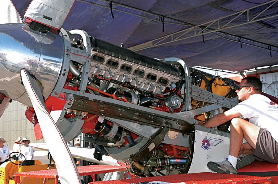
Unlimited P-51 racer Strega shows off its Rolls-Royce Merlin V-12 during pre-race repairs. At about 140 cubic inches each, Merlin cylinders are just 16 cubic inches smaller than the contemporary R-2800 radial’s jugs. Better balanced and inherently less stressed around the crankshaft, the Merlin can safely turn 15% higher rpm. Advantage V-12 in sprint applications, but the extra rpm isn’t much help in long-haul cruising.
A major benefit of the inline-4 architecture the Wrights selected is a short, stiff crankshaft, yet another concept playing a surprisingly important and reoccurring part in aviation engine design. Large-displacement cylinders place a premium on crankshaft torsional rigidity because the fewer, but stronger, power strokes twist the crankshaft with each cylinder’s firing. Shorter crankshafts are inherently stiffer and need less reinforcing mass.
Adding two cylinders, we arrive at the beautifully balanced inline 6-cylinder. Narrow, these package nicely in single-seat airplanes, and Mercedes and BMW built excellent examples during WW-I (180 hp and 675 pound-feet of torque at 1400 rpm), with the form remaining popular with Menasco and others until WW-II. But crankshaft rigidity is a factor, plus the overall engine is relatively long in small general aviation craft, and worst of all, gathers weight quickly.
Joining a pair of inline 4-cylinders to make a vee arrives at one of the great engine layouts: the V-8. The crankshaft is shorter than an inline-6’s because the cylinders can be somewhat overlapped, and large displacement is possible with relatively small frontal area. The more frequent power impulses help with balancing and torsional concerns as well.
The same is true but more so by joining a pair of inline-6’s into a V-12. That’s because a V-8 balances with the cylinder banks separated by 90 degrees, whereas the V-12 needs a narrower 60 degrees for less frontal area. The more frequent power impulses of the V-12 help with the admittedly long crankshaft’s torsional rigidity needs, and all considered, the form remains an elegant way to package large displacement engines. Upward spiraling weight and friction characteristics make the V-12 less tenable in small displacements.
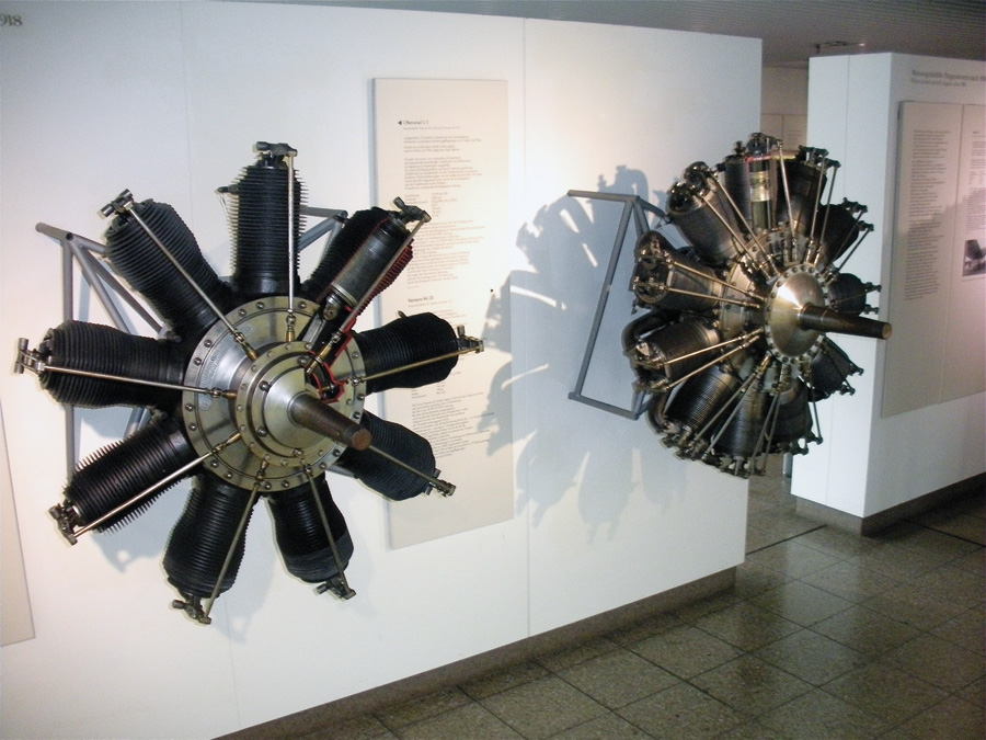
Oberursel and Siemens rotaries hang on the Deutsches Museum wall. Imagine all this mass rotating with the propeller and a tiny rudder out back. Light and powerful, such rotaries had their day in WW-I but were eclipsed by V-8s by war’s end.
Rotaries & Radials
Cooling was a major issue of pre-WW-I engine designers, leading Clerget, Gnome, Le Rhone and others to the rotary layout. Here the cylinders resemble spokes emanating from a hub, the hub being the crankcase. The authenticating characteristic is the crankshaft is bolted to the airframe, the propeller is bolted to the front of the crankcase, and the entire engine and propeller spin around the stationary crankshaft! This provided adequate cooling airflow when mounted to the painfully slow aircraft of the day. An extreme design, rotaries produced nasty gyroscopic forces and allowed only primitive intake and exhaust systems, but provided good power to weight. Approaching 200 hp their mass and resulting gyroscopic forces became overpowering, making the type obsolete before the end of WW-I.
Outwardly radials look like rotaries, but get the cart behind the horse by bolting the crankcase to the airframe and letting the crankshaft rotate. Like rotaries, radials can have multiple rows of an odd number of cylinders; one and two rows are common, but Pratt & Whitney’s R-4360 had four rows. The number of cylinders per row is always odd. Seven- and 9-cylinder single-row, plus 14- and 18-cylinder twin-rows were popular.
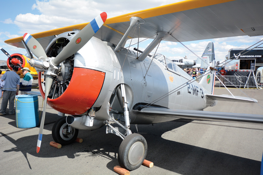
An engine’s form and airframe installation are deeply intertwined. This 1938 Grumman F3F-2’s huge cooling inlet area, no cowl flaps, and downward facing collected exhaust were all old ideas five years later. The Grumman’s 1000-hp R-1820 Wright radial gave 250 mph, almost as fast as today’s Reno biplane racer Phantom with one-third the muscle.
Radials obviously differ substantially in detail from vee and flat engines, but major radial advantages are they can package huge cubic inch displacement in an arguably compact and definitely weight-conscious format. Radials enjoy very compact crankshafts, but all the cylinders per bank attach to a single connecting rod throw on that crank. This leads to a humongous connecting rod, bearings and so on, all of which discourage high rpm. So do the large pistons and typically long strokes.
Another radial characteristic is complicated rotating forces. Only the one master connecting rod attaches directly to the crankshaft, while the other link rods connect the remaining pistons to the single master rod. The result is a riot of oscillating weight, rod geometries, and thus complex balancing issues as reciprocating weight rises in larger radials.
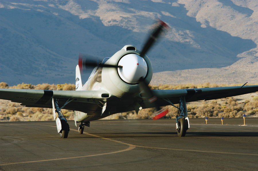
Almost too obvious to note, radials present billboard frontal area. Late WW-II research showed all of this can be mitigated by careful cowling design employing minimal inlet area plus exhaust pipe energy on the exit as this racing Yak shows. But the engineering needed to efficiently mate a radial to its cowling and airframe is seemingly beyond most homebuilders’ interest or abilities.
All told, radials are traditionally larger displacement and turn pedestrian rpm. Add in their Henry VIII frontal area and manly cubic inches to get a healthy appetite for gasoline, albeit in a light, muscular package. Even so, in the pre-dog whistle era, big radials financially outperformed high-strung inlines in airline (and even bomber) duty, even if the inlines held speed and fuel efficiency advantages. Today general aviation airframes are too small to make use of a couple thousand cubic inches the radial architecture is best at, and so the small Rotec radials satisfy an important nostalgic niche, while the Soviet-era M14P provides tight CG packaging in power-hungry aerobatic aircraft.
Flat and Happy
Continental can lay claim to the first horizontally opposed 4-cylinder aircraft engine—the 37-hp, 143-pound A40—dating from 1930. By 1938 Harold Morehouse at Lycoming designed the similar O-145, and rival Franklin released a flat-four of their own. At the time radials and inlines prevailed, but it’s no coincidence these manufacturers simultaneously pioneered the flat layout as the design offers compelling advantages.
If you think of the flat engine as an inline with the cylinders vee’d so far they’re 180-degrees apart, it’s easy to see the flat engine is a little shorter than an inline because the cylinders can be overlapped. Again, a stiffer crankshaft results. Once cowled and baffled, the flat layout, even when overall a bit long in 6- or even 8-cylinder form, nevertheless air-cools well. Frontal area is rather small, and if bulged cowl cheeks, and especially a prop extension, are utilized, a relatively fine entry is easily achieved. From a balance perspective the flat layout is identical or better than an inline-4 or -6, and no heavy or expensive crankshaft counterweights are required at lower engine speeds. The form even lends itself to water cooling if desired—see Continental’s Voyager series.
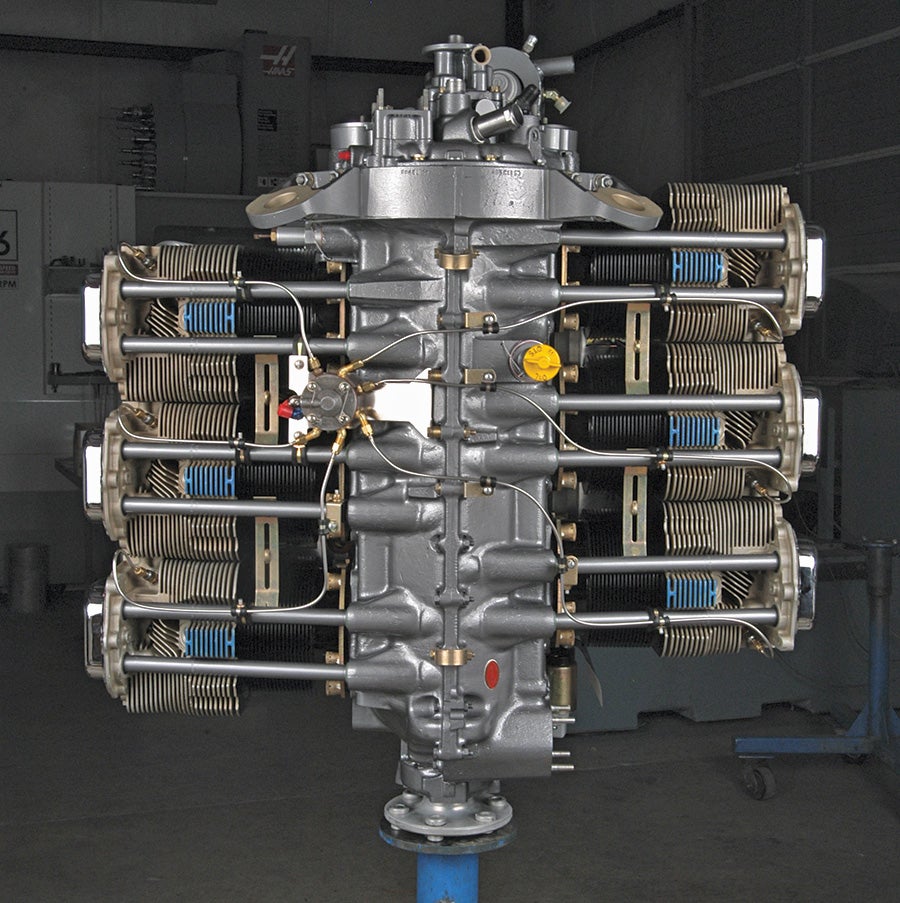
Simplicity, and thus reduced weight and low cost, are flat-engine virtues. This Lycoming 540 looks especially lean without its visually bulky baffling, and it’s no illusion. Hot-rodded with 10:1 pistons, this example dynoed 320 hp and 640 pound-feet of torque at 2700 rpm, but weighs just 400 pounds. The offset of the cylinders is also readily apparent here. Each bulky, finned cylinder has its own crank throw; with narrower water-cooled cylinders, the engine could be even shorter.
Definitely not least of its virtues, the flat engine can be quite lightweight. The compact cylinder arrangement, and thus shorter overall length, is the primary reason, but also a good amount of the cylinder and crankcase hardware can do double duty. Besides not needing crankshaft counterweights, the balanced forces and shorter crankshaft naturally support large-displacement cylinders on a light crankcase.
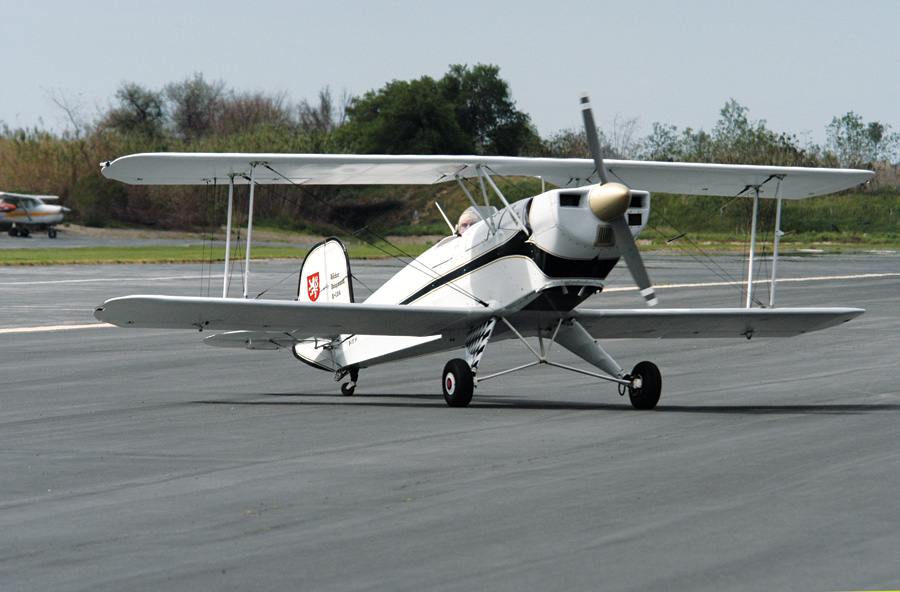
Horizontally-opposed engines may be near perfect technically for light aircraft but, ugh, the looks. The late, great Mira Slovak’s Bucker Jngmann went from inverted inline Hirth to horizontally-opposed Lycoming for many practical reasons, but it turned the Jngmann’s original narrow nose into an ugly nostrilled box.
In short, the horizontally-opposed engine landed in a happy spot just prior to WW-II and has been the de facto general aviation engine since. That has lead to economies of scale for several generations of pilots, the result being the light-plane world understands the layout to the point that trying anything else today smacks of wild enthusiasm for the untried. That’s fine for what it may have done for us in cost containment, but it’s stifling too as the ubiquity of flat engines has led to a sameness in airframe shape that’s frankly a little boring.
Next time we’ll detail engine breathing on the intake side.








This was a terrific article. Not only did I have auto shop, but I’ve rebuilt an engine. Nonetheless this hands on experience didn’t provide the basics around the tradeoffs surrounding engine design.
Thanks!
Hi Tom,
Thanks for the great article! Why does horsepower and torque equal out at the specific rpm of 5252? Thanks, Bryce
It’s in the math. Torque is measured directly by a dynamometer and horsepower is calculated using the dyno’s torque reading and the formula:
horsepower = rpm x torque / 5252
The 5252 is a constant derived from a unit of power James Watt developed back in the 1600’s to measure the amount of weight a horse could lift out of a mine in a minute. Reducing Watt’s calculation gives the constant of 5252, which in turn means the torque and horsepower curves will always cross at 5252 rpm. It’s also why it’s called horsepower.