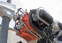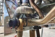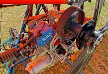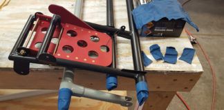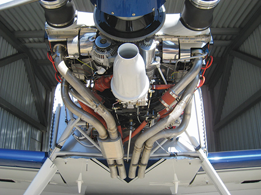
This RV-7 features the Vetterman four-tube system with cabin heat drawn from a muff that wraps around two of the pipes. The engine is fuel injected, so it does not need a carburetor heat muff.
Once the fuel and air that an engine ingests have done their work, they must be expelled from the airplane and sent on their way. This is primarily what exhaust systems do, some better than others. In addition, as a convenient source of heat, these systems can also provide warmth to the cabin and help prevent ice from forming in carburetors. Most people buy ready-made exhaust systems, but sometimes the need for a custom installation or just the desire to save a buck will push some amateur builders toward rollin’ their own.
Do It Yourself
The preferred material for airplane exhaust systems is 321 stainless steel, though some manufacturers and builders use 304 stainless. Stainless-steel exhaust-system components are readily available from Aircraft Spruce & Specialty, Wicks or other aviation parts suppliers. Some custom automotive suppliers also carry stainless-steel exhaust components. Tubing and bends should have a wall thickness of at least 0.035 inches, but 0.049 makes for a sturdier, longer-lasting system. For best results, the stainless should be welded with a TIG welder (also called heli-arc or tungsten inert gas). It can be welded with oxyacetylene equipment, but it is fairly difficult to make nice-looking welds with such gear. Bends are readily available in 45, 90 and 180°. Other bend angles are made by cutting out a portion of the next larger bend and welding it to straight tubing. Complex systems can end up with a lot of cuts, bends and welds, but just about any combination of twists and turns can be assembled with these basic components.
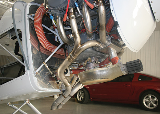
This Super Cub-type plane employs a Vetterman system with a front-mounted heat muff to provide cabin heat and carburetor heat from one compact unit.
Even though it is more common to see them made of stainless steel in airplanes, exhaust systems can be made out of mild steel. Exhaust-system components in mild steel such as tubing (both straight and bent) flanges, joints and collectors are readily available from a number of automotive sources. The wall thickness for the 1.5-inch or 1.75-inch outside-diameter mild steel tubing should be 0.049 inches. Mild steel is much less expensive than stainless, and it is easily welded with oxyacetylene equipment, which stainless is not. The downside to mild steel is that it does not last as long. One also occasionally sees exhaust systems made of more exotic materials such as Inconel, but these are rare and expensive, reserved primarily for racers and those who wish to maximize performance regardless of cost.
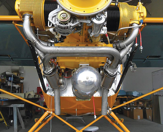
A Vetterman exhaust installed on an Experimental Super Cub. This system features dual muffler shrouds for improved cabin heat. No carburetor heat muff is needed with this fuel-injected engine.
Buying Better for Most Builders
For most of us, a prefabricated system will be the way to go. There are a number of choices available for the more common kits and plansbuilt airplanes on the market. Some systems include mufflers, and others are just pipes with no attempt to deaden the note of the exhaust. In Europe, such open exhaust systems will quickly get you in big trouble. In the U.S., it is still possible to use them in most places, but more and more airports in urban areas are enforcing sound restrictions with big fines attached. If you decide to go without a muffler, just remember that you may not be welcome everywhere.
Some of the lightest, simplest and most popular exhaust systems available are the Vetterman systems. The company is best known for its work with the Van’s RV series of airplanes, but owners of many other kits can now find Vetterman exhaust systems that will fit their planes. These systems are available directly from Vetterman, through Van’s or from the Aircraft Spruce catalog. They are light and nicely made, and people who have these systems generally are pleased with them.
A number of other kit makers offer exhaust systems custom-tailored to fit their particular airplanes. These can often be adapted to fit other makes and models, so it is worth looking at these options if you are having difficulty finding a system that works for you. For example, there are a lot of non-RVs out there flying with RV parts. There are a number of small custom-exhaust-system manufacturers that can help you out. Contact the members of your type club or builders group to see whom they recommend. These groups are a good place to start looking for parts for your project.
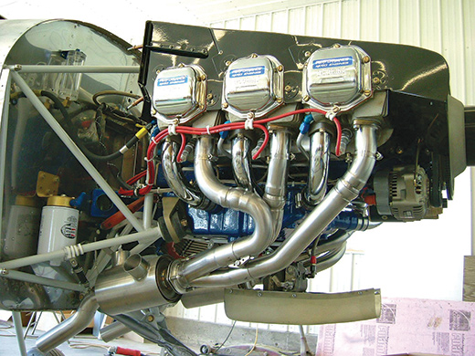
Vetterman now makes systems for the popular RV-10 with its six-cylinder engine.
Tuned Exhaust Systems
The first thing most people ask when the subject of tuned exhaust systems comes up is: Do they really work? The answer is yes, assuming they are properly designed and manufactured. The basic theory is that when the exhaust valve opens and the gases are allowed to escape the combustion chamber, a positive-pressure pulse is sent down the exhaust pipe. When that pulse gets to the end of the pipe and is allowed to rapidly expand into the open air, it reflects a negative-pressure pulse back up the exhaust pipe toward the exhaust valve. When you see negative pressure think of suction—that’s how it acts.
The negative-pressure pulse can be used to scavenge exhaust gases out of the cylinder and help pull the intake charge in. This is where the increased horsepower comes from. The trick is that the timing of all of this must be just right to optimize the effect. In a car this is tough because the rpm range is so wide, but airplanes operate over a narrow rpm range, so picking the correct length is relatively easy.
Here’s how it works. The pressure pulse travels through the pipe at the speed of sound. At a specific engine speed, say 2500 rpm, it is fairly straightforward to calculate the time from when the exhaust valve first opens until it starts to close again. Then it is just a matter of building a system with the correct length of pipe, so that the negative-pressure pulse arrives back at the face of the exhaust valve at the optimal moment. When this all works as planned, the negative pulse draws the remaining exhaust out of the cylinder and helps propel the intake charge in. But if the negative-pressure pulse arrives too early, or, especially, too late, it is of little help. (This is a greatly simplified version of what actually happens, but you get the idea.)
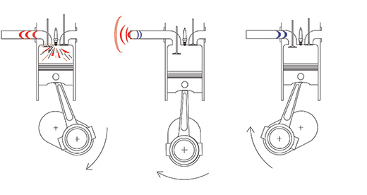
| 1. The exhaust valve begins to open as the piston nears the bottom of the power stroke, sending a positive-pressure pulse down the exhaust pipe. | 2. When the positive-pressure pulse reaches the end of the exhaust, it rapidly expands and reflects a negative-pressure pulse back toward the exhaust valve. | 3. When the negative-pressure pulse arrives back at the exhaust valve, it draws exhaust gases out of the cylinder. |
Once the optimum length is determined and verified with testing, it is just a matter of getting it to fit inside the engine compartment, which may not be as simple as it sounds. In the final analysis, the proof is in the pudding. You build a system, put it on your plane, fly it and see what happens. If it goes faster, you did a good job; otherwise, it’s back to the drawing board.
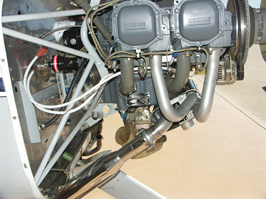
A Power Flow exhaust system being installed in a GlaStar.
Power Flow Systems, Inc. is the primary maker of tuned exhaust systems for GA airplanes. The company has a limited number of systems designed specifically for Experimentals and a greater number of systems designed for certified airplanes, some of which may work well in your homebuilt, either as is or with minimal modification. These systems do produce measurable performance gains, proving that they increase horsepower. The disadvantage of the Power Flow systems is that they are fairly expensive compared to other systems. On the plus side, they are well made, include mufflers to help reduce noise and provide reasonable heat for cabin- and carb-heat needs. The same effect could be duplicated by an amateur builder, but the difference is that the company has done the research and the testing to make sure the systems work. Vetterman is also now producing tuned exhaust systems, though they are set up somewhat differently. They simply run four exhaust pipes of a specific length out the bottom of the airplane with no collector or muffler. Again, simplicity rules the day at Vetterman, resulting in a lightweight product at a good price.
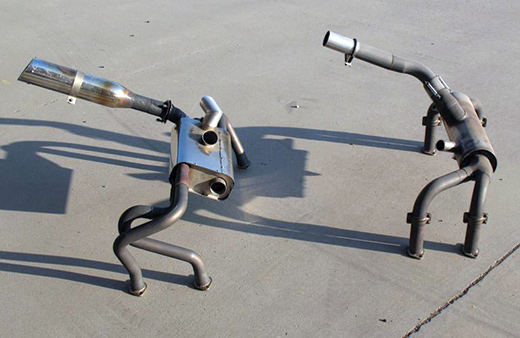
Shown here are a traditional Cessna-type exhaust system and a Power Flow system, both designed to work on the GlaStar or Sportsman with a 180-hp engine. The Cessna-type system shown on the right pipes exhaust into a large can with internal baffles, which serves as a muffler and an efficient source of heat for cabin- and carburetor-heat needs. The Power Flow system on the left has a large heat muff with a separate muffler attached to the tailpipe.
Another company that has emerged to serve the needs of amateur airplane builders is Atelier Chabord. Based in France, the company is used to dealing with the much stricter noise regulations of the European Union. It makes tuned exhaust systems in stainless steel and Inconel. In addition to Experimental systems, the company also produces exhaust systems for some certified airplanes. As you might expect, the Inconel systems are considerably lighter (0.024-inch wall thickness) and more expensive than the stainless systems.
Some kit manufacturers have contracted with vendors to make tuned exhaust systems for their customers. Glasair, for one, makes such a system for its popular Sportsman 2+2. It seems likely that others will eventually follow suit. It also seems like a fertile field for smaller custom-exhaust shops to explore. These systems are not inexpensive, but compared to the cost of other things you can do to legitimately add horsepower to your engine, they are at least reasonable.
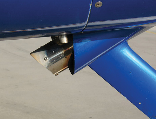
Fitting the Power Flow exhaust to the Sportsman required some cowl modifications to provide the proper clearance. A minimum of three-quarter-inch clearance should be provided to avoid heat damage to paint and fiberglass.
Exhaust System Dos and Don’ts
Do make sure that all joints fit tightly and that all welds fully encircle their joints when making your own or installing a manufactured exhaust system. Exhaust leaks can become silent killers by allowing carbon monoxide (CO) to linger in the engine bay, where it can seep into the cabin through the cabin-heat system. A solid seal between the exhaust-stack flanges and the cylinder heads is also essential. Before installing your system, lightly file the flange surface with a flat file. If there is any evidence of the flange not being perfectly flat, correct it at once. A little judicious hammering and filing should get the mating surface flat without too much trouble.
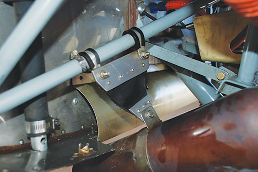
This Power Flow installation required a custom-made exhaust hanger for the muffler.
Use new gaskets and lock washers each time you install or reinstall your exhaust system. Gaskets get crushed by the installation process and take a set from the heat of the engine. They will not seal as well the second time around. The same goes for those lock washers. Ideally the nuts on your exhaust should not loosen between yearly condition inspections. Always using new lock washers goes a long way toward achieving this goal. Also, remember to torque exhaust nuts to the recommended torque value (204 inch-pounds for engines with two 5⁄16-18 studs per exhaust port). It is also best to fit the entire system with the nuts loose and then torque everything starting in the front of the engine, and then moving rearward. Bolted clamps or other connections should follow this same path of front to rear, engine to tailpipe.
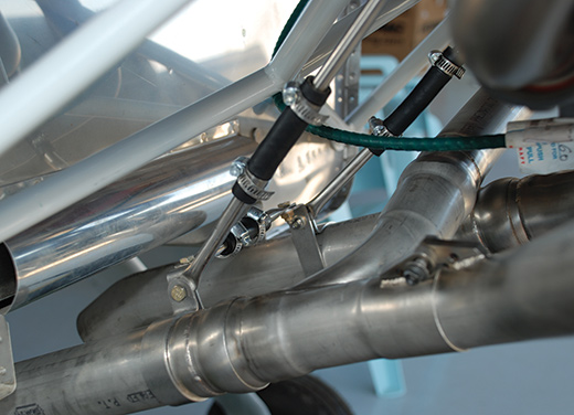
Reinforced rubber fuel lines are used in the typical Vetterman installation to provide a flexible connection between the exhaust system and the airframe.
Allow for some movement when supporting exhaust-system components from the airframe. The engine moves around quite a bit, so any exhaust system that is attached to the engine and the airframe without flexible connectors will quickly fall apart from that movement.
Route all wires, oil lines and fuel lines well away from exhaust pipes. A clearance of 1.5 inches will normally suffice. Also, be mindful of getting too close to the engine cowl with exhaust-system components. The heat from these can ruin fiberglass and blister paint. Install a heat shield made of thin aluminum if clearance is a problem. Make the heat shield larger than the affected area. You can attach it to the exhaust system or bond it to the cowl with epoxy. Aluminum tape can often be applied to the inside of the cowl in critical areas and will diffuse the heat enough to avoid damage to the fiberglass or paint.
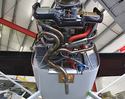
Glasair has a special four-into-one tuned exhaust system made specifically for its Sportsman kit.
Don’t fly your new airplane through the flight-test period without checking the cabin for CO. Carbon monoxide detectors can be acquired inexpensively from almost any pilot-supplies vendor. Verifying the initial integrity of the exhaust system should be an early action item on your Phase I flight-test plan.
Don’t use gasket sealers or high-temperature RTV on your exhaust gaskets. They won’t work if there is an actual leak. Also, a leaky exhaust flange initially torqued to 204 inch-pounds won’t leak less if you torque it to 300. Instead, it will likely leak more, and you will risk damaging the exhaust stud in the cylinder head. Fix the problem the right way and be done with it.
Don’t forget that exhaust nuts on Lycoming engines are coarse thread, not the more typical fine thread of other airplane fasteners. Forcing a fine-thread nut onto the exhaust stud will cause big problems.
Exhaust systems need to be inspected annually, or more often if necessary, to be sure they have not cracked or begun leaking at the exhaust flanges. Such an inspection should include removing the carburetor/cabin heat shrouds from the exhaust system and looking at the underlying components. As mentioned, leaks can be deadly, especially in the cabin-heat system. Leaks between the flanges and the cylinder heads can erode the metal of the heads and lead to costly replacement or repairs. Exhaust systems are generally simple and reliable, but they do need regular care to keep them working properly. The manufacturer of your exhaust system can give you specific guidelines for maintaining its product.
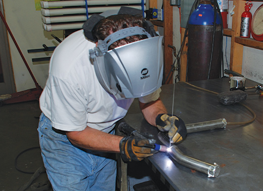
Master welder Rick Lefever demonstrates the preferred technique for TIG welding stainless-steel exhaust tubes. The interior of the tubes should be purged of oxygen by running argon gas into them before welding. This makes for cleaner welds and less cracking later.
Carburetor Heat and Cabin Heat
With no other readily available source of heat, it falls to the exhaust system to warm the cabin and prevent icing in the carburetor. Simply placing a stainless-steel sheet-metal shroud around the muffler and forcing air through it is usually sufficient for these needs. A simple butterfly valve alters the source of engine-intake air from the air-filter box to the muffler shroud (sometimes called a muff). This warms the air sufficiently to prevent ice from forming in and around the carburetor, which can potentially stop the engine.
Cabin heat is similarly drawn from a shroud around the muffler, which in turn gets air from a pressurized source such as a NACA scoop on the engine cowl. Be sure that the source of fresh air for your cabin heat comes from a place where exhaust gases will not be able to contaminate incoming air. Problems can also arise when exhaust systems do not have much in the way of a muffler to provide sufficient surface area to heat the air. For instance, many Vetterman systems will require installation of a second muff to generate sufficient heat to warm notoriously cold airplanes such as the RV-8. The higher you fly and the farther into cold country you venture, the bigger this problem becomes. The Cessna-type muffler may not flow as well, and it certainly weighs more, but it provides pretty good heat for the cabin. Airplane building is about trade-offs, but be sure you understand what is involved as you make your choices.
Exhaust leaks can become lethal when they intrude into the cabin-heat system. Any good exhaust system must get all of the engine exhaust out of the cowl area while the engine is running. It is vital to ensure that this is indeed the case early in the Phase I flight-test period. A careful inspection of the exhaust system after the engine runs for the first time must be on your checklist.
Next time we’ll tackle engine controls, and after that we will leave nuts and bolts behind and start looking at electrical and electronic components.

