On a Saturday in early August 2015, I was on my first instrument rating lesson, something I had been putting off for some time. The lesson was pretty straightforward—climb up to 6500 feet heading 360, followed by a series of ascending and descending turns while under the hood. Next up was an approach into Capital City Airport (KCXY) near Harrisburg, Pennsylvania. After figuring out how to get the Grand Rapids EFIS to properly display the CDI/HSI from the Garmin 430W, we were in business. Next up was a practice hold, followed by a GPS approach into York, Pennsylvania (KTHV).
As we were approaching the fix for the hold, the airplane developed a very noticeable shake. Clearly something was not right with the engine. Automatically without even thinking, I pushed the mixture full rich and turned on the fuel pump. My CFII looked out the window to point me toward York airport. I didn’t have it in sight, as my mind was going a million miles an hour. I was lucky to have him in the airplane to point me where I needed to be. Cockpit resource management kicked in between us, and we were working as a team instantly. The engine was still developing power, and we were within easy gliding distance of the airport, just in case the engine had other ideas. A glance at the engine monitor showed what the root cause of the issue was: The EGT for the #2 cylinder was non-existent. The CHT was decreasing quickly. It was clear that the #2 cylinder was not producing power.
At 2000 feet over KTHV, the engine all of the sudden started performing normally again. The EGT immediately came back to normal, and the CHT was increasing slowly (from memory, it dropped from 350 to 190). I glanced at my flight instructor, and we both thought it would be better to put the airplane down back home at Carroll County Regional Airport (KDMW), a short 10 minutes away if we could make it there safely. We circled over KTHV, gaining altitude and observing the engine. Things seemed fine, as all engine parameters looked to be back in the green. We headed to KDMW. Roughly halfway to KDMW, the engine stumbled very quickly. Not enough for the engine monitor to notice anything, but both of us definitely heard something. We stayed high and circled down to a non-event of a landing.
Once back at KDMW, my friend John Sannizzaro and I started to look for the culprit of what just occurred. We removed the cowling and started digging around the #2 cylinder. Having a full engine monitor with probes on each cylinder was vital to figuring out where to start looking. Both spark plugs looked to be in fine condition (E-MAG on the top plug with an auto plug, Slick mag on the bottom with a massive electrode plug). Next up was a compression test—78/80, with the slight leakage coming through the rings (audible noise through the oil filler tube).
Naturally, I would be unlucky enough to have an intermittent issue. But how could I fix it?
Cause
An engine needs three basic criteria to work: spark, compression, and fuel. If the spark was lost, both the E-MAG and Slick mag would have stopped firing in the #2 cylinder. If the E-MAG quit, the other cylinders would have symptoms of elevated EGTs. That wasn’t the case.
The lack of fuel was a more likely culprit, especially if an injector was clogged. However, from past experience, I found it to be unlikely that an injector would be clogged and then immediately unclog. Typically when an injector gets clogged, the EGTs are elevated, the exhaust makes a popping sound, and the issue doesn’t cure itself.
The last possibility was lack of compression. What could cause this is a stuck exhaust or intake valve being open. An open valve during the compression stroke of the engine would definitely cause the symptoms I saw.
So how does a valve become stuck? The valves in a typical Lycoming 320/360/540 engine ride through guides. On top of the guides are springs connected to the stem of the valves, which keep them closed until the camshaft decides they should open. A sticky valve occurs when the valve stem can no longer move through the guide freely, and it becomes bound to the guide. There are two possible ways a valve can be stuck. When a valve is stuck in the closed position, the damage most likely to occur is a bent pushrod, as something has got to give. The other way, which happened me, was the valve was stuck open.
Lycoming Service Letter L197A, “Recommendations to Avoid Valve Sticking,” attributes sticking valves to oil contaminants and combustion residue. Both of these can build up on the valve stem and guide and interfere with the stem’s movement. The valve not being able to fully open or close causes incomplete combustion, which in turn forms more deposits and worsens the issue. Lycoming’s recommendations for minimizing/preventing this buildup include:
1. Ensuring the air filter is clean.
2. Regular oil changes.
3. Using quality fuel.
4. Flying regularly.
Lycoming also suggests avoiding:
5. Infrequent ground runs where the engine is not brought up to operating temperatures.
6. Long ground runs, which can cause overheating.
7. Running too rich.
8. Rapid engine cooling.
9. Shutting down the engine too soon, before it is allowed to cool.
Inspection
Lycoming Service Bulletin 388C specifies that every 400 hours (300 for helicopters) the engine should be inspected for sticky valves, or earlier if the engine is suspected of having a sticky valve. Reading through this service bulletin goes into detail of specialized tools to measure how much play the valve stem has in its guide—otherwise known as the “wobble” test. For my particular issue, it was very clear that I failed the test. I could barely move the valve stem in and out of the guide. A few A&Ps I spoke with said it should be easy to move the valve in and out of the guide and spin it around.
Warning Signs
So, what are the warning signs to look for before you experience a full-on stuck valve at an inopportune time? One thing to look for is what is known as “morning sickness” of the engine. Morning sickness is when the engine is first started and there is a slight miss or intermittent hesitation in the speed of the engine. This usually occurs when the engine is first started because the clearance between the valve stems and valve guides are at a minimum when the engine is cold. Other indications of morning sickness include colder than normal EGTs and CHTs for a particular cylinder. In my case, I cannot recall any times my engine seemed to be running rough when first started. However, over the last few months, I did notice the engine missing in cruise configuration running lean of peak. While I have no consequential data that this miss was an indication of a sticky valve, I can indisputably say I haven’t had a miss in cruise since.
Prevention
Almost as soon as I discovered the reason for my engine issue was a stuck valve, the airport locals immediately gave me their recommendations for why it happened and how to fix it. One theory was the oil I am using (Phillips X/C 20W50 for the last two oil changes, before that Aeroshell 15W-50 for 150+ hours) was known to cause sticky valves in Lycomings, and I should give away the extra quarts I have of it and switch to Aeroshell W100. Another theory was I should be running an additive in my fuel to scavenge the potential lead buildup. TCP Fuel Treatment and Marvel Mystery Oil were two products recommended to me that I should add to my fuel. Lastly, it was recommended that I not run lean of peak, as it “costs more to fix the issues of running LOP than LOP saves in fuel.” While I kindly acknowledged and appreciated the advice, the last two recommendations were also listed in Lycoming Service Letter L197A. I believe the cause of my issues were a combination of running too rich on climbout, as well as a number of ground runs when my airplane was new and I was working through some issues. Nevertheless, I am going to start adding some Marvel Mystery Oil to my fuel and keep track of any tangible evidence of it helping with the engine scavenging the lead better.
Tools
Here are the tools I used to fix the stuck valve:
1. Spring Compressor
a. Aircraft Spruce— p/n 12-21520 for $60
b. ACS, p/n 12-00202 for $77.
c. SkyGeek sells this variety for $150, p/n ATS3602
d. Valve Wizard for $150
e. Build your own from pry-bars for $18 and one hour of labor!
2. Wood Dowels
a. inch for compressing the hydraulic lifters
b. 3/8 inch for tapping the valve into the cylinder
3. Reamers
Check with your engine manufac-turer for the proper reamer to use. The technical support at Superior recommended a 0.4995-inch reamer for the exhaust valve. The Lycoming specs for the exhaust valve guide diameter is a minimum ID of 0.4985 inch and a max ID of 0.4995 inch. The intake valve guides are slightly smaller with a minimum ID of 0.4040 inch and 0.4050 inch max.
4. Mechanical Pickup Tool
I suggest the lighted General #70396. The LED light comes in very handy, and the tool can be had for under $10.
5. Hook and Pick Set
I used Harbor Freight #93514—the smaller the better!
The Fix
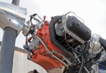
With all of the background of what causes this issue, and the recommended inspection intervals, let’s get into the process of fixing a sticking valve. My process loosely follows Lycoming Service Instruction 1425A (“Suggested Maintenance Procedures to Reduce the Possibility of Valve Sticking”). It is what I used on my Superior IO-360-B1A2 engine to fix the exhaust valve. I highly suggest you consult your engine manufacturer for their recommended procedure to fix a sticky valve.
I must add, this job isn’t for the faint of heart. While nothing here is overly complicated, and I found this job to be rather easy, I also have nearly a lifetime of working on engines ranging from lawn equipment and car engines to outboard and inboard boat engines. Also, I must make it clear that I am not an A&P and have no formal training in fixing aircraft engines. All of this information was gathered by talking to friends, several A&Ps, and research on the Internet. Proceed with caution!
Removing the Valve Spring
1. Remove the valve cover of the cylinder suspected of a sticking valve. Be ready for some oil to drip out of the top end of the cylinder. Place appropriate rags around the engine and a drip pan under the engine.
2. Remove the top spark plugs from all cylinders and both plugs from the offending cylinders. This is both for safety, and it makes rotating the propeller easier.
3. Rotate the propeller so both valves are fully closed. You will know this because the top of both rocker arms will be closest to the pushrod shroud tubes.
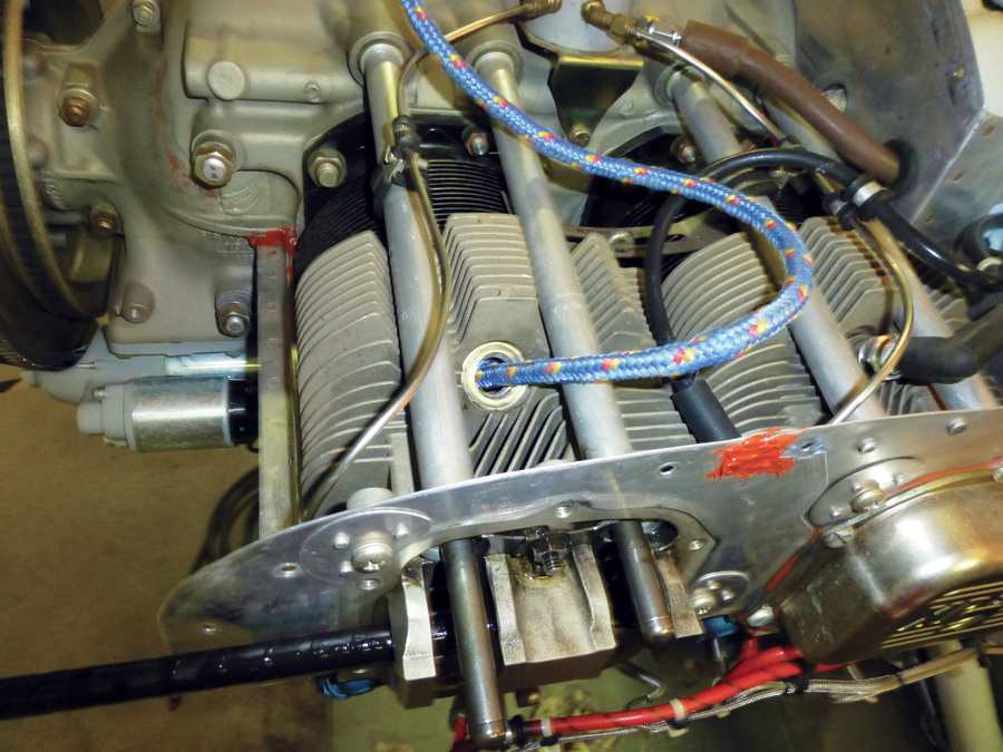
4. Remove the rocker shaft. You should be able to easily push this out with just the force of your hands. If this is not possible, double-check that both intake and exhaust valves are fully closed. Note the direction the rocker shaft came off (Figure 1).
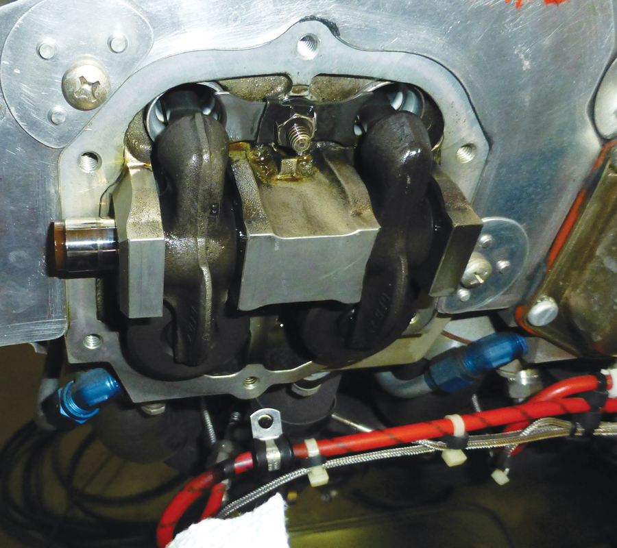
5. Once the rocker shaft is removed, make sure the two rocker arms do not fall out. Remove each rocker arm individually and place it in a container. For my engine, both rocker arms were identical, but this may not always be the case (Figure 2).
6. Remove the pushrods from the pushrod shrouds. They may be full of oil, and there could also be oil that drips down the pushrod shrouds. Note which side and direction each pushrod is installed.
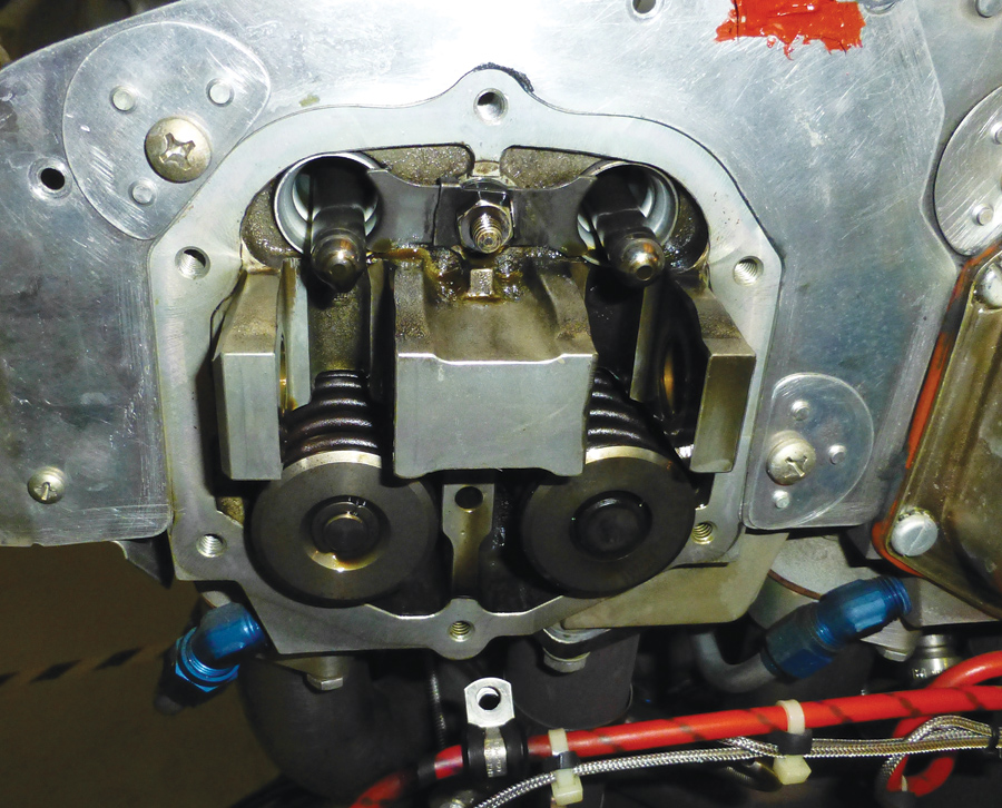
7. Remove the cap on top of the exhaust valve. Use a pick to remove it if you cannot by hand. Try to minimize the use of a magnet whenever possible. A magnet could cause parts of the engine to become magnetic and attract ferrous material, causing premature wearing (Figure 3).
8. The next step is to prevent the valve from entering the cylinder while being compressed. There are two ways of going about this. One method, Lycoming SI 1425A specified, is inserting eight feet of 3/8-inch nylon rope through the top spark plug hole. The other method is using compressed air to pressurize the cylinder. The compressed air method involves using an adapter that fits into the top spark plug hole and has a male air hose quick-disconnect fitting on it (one came with my ATS differential pressure tester). Additionally, the bottom spark plug needs to be installed in order to seal the cylinder.
I chose to use the rope method. I have read a story of how the rope decided to knot itself inside the cylinder, causing the mechanic to pull the entire jug to free the rope. If you decide to use the rope method, feed roughly eight feet of rope into the cylinder and then rotate the propeller until the rope is pressed between the valves and the top of the piston. You might need an assistant to hold pressure on the propeller while you move to the next step. (This step may be optional depending on how stuck your exhaust valve is.)
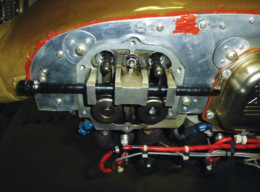
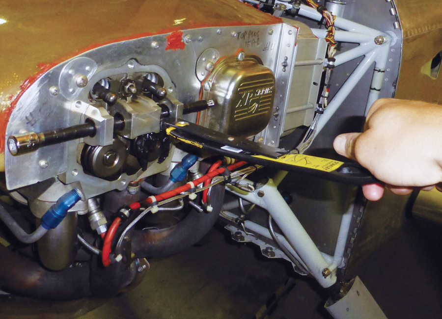
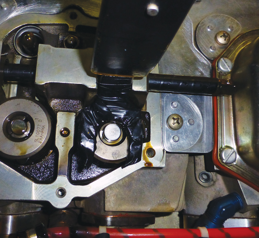
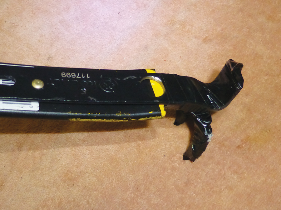
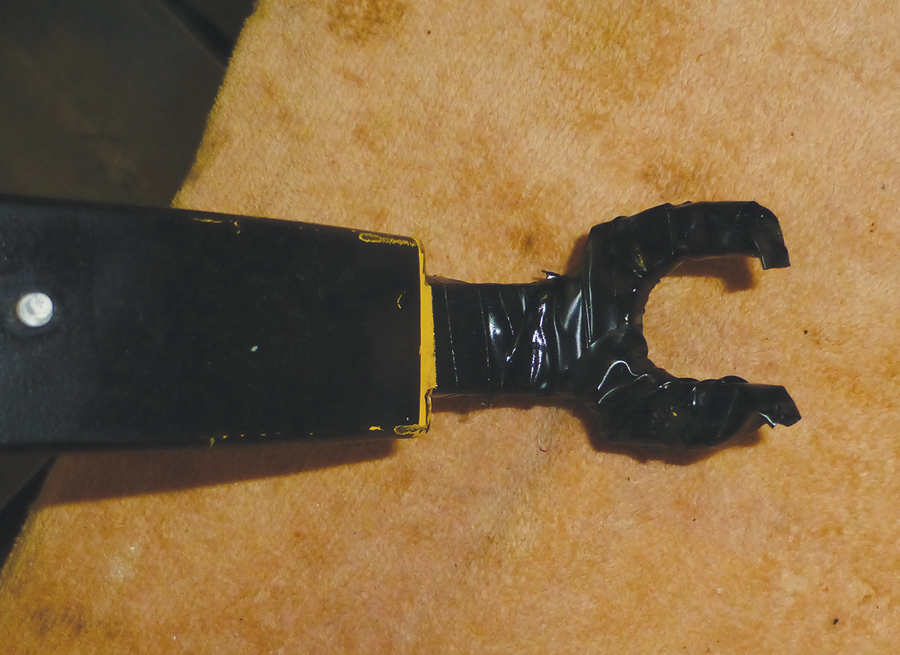
9. Compress the exhaust valve spring with the spring compressor. The method to do this is different with every tool out there. Consult the tool’s literature for the proper way to use it. For my homemade tool (see sidebar below), I inserted a 3/8-inch extension bar wrapped in electrical tape through the holes where the rocker shaft was (Figure 4). This bar is used for the valve compressor to pivot around as it compresses the spring. Compress the spring enough to gain access to the keys (Figures 5 and 6).
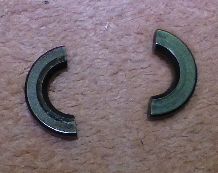
10. Using a pick set, reposition and rotate the keys until they are overlapping. Gently move the positon of the spring in relationship to the valve stem in a way to make the keys removable. Use a pick to pull the keys out (Figure 7).
11. With the keys out, the spring will come out freely.
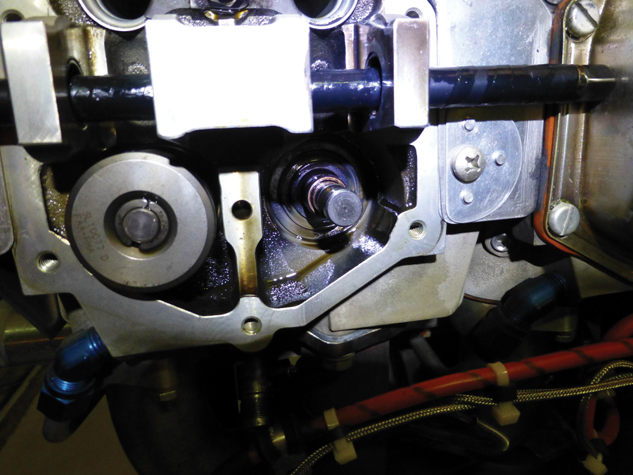
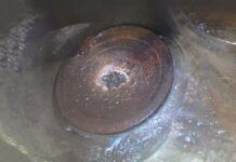
12. Now is the moment you have been waiting for. Check the play of the valve in the valve guide. Check how easy it is to push it in and out of the guide, as well as spin the valve within the guide. If there is any binding noticed, you have a stuck valve (Figure 8). If in doubt, perform a wobble test. If the wobble test passes, skip the next section and go to Reassembling the Exhaust Valve.
Reaming the Exhaust Valve Guide
1. Once you have determined you need to ream the guide out, the first step is to partially push the exhaust valve into the cylinder. You don’t want to fully push the valve into the cylinder, as getting it back into place is difficult. The easiest way to do this is to drop the valve into the cylinder enough so you can catch the end of the valve stem through the exhaust port with a mechanical pick-up tool. Also, you want to make sure the piston is at bottom dead center to prevent any damage between the valve and the piston.
2. Rotate the propeller so the piston of the cylinder you are working on is at bottom dead center.
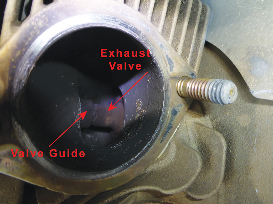
3. Remove the exhaust to gain access to where the valve will exit the stem (Figure 9).
4. My exhaust valve stem was very tight in the guide. I could push the stem of the valve to the top of the guide. After that, I used a 3/8-inch short wood dowel resting against the top of the exhaust valve. I lightly tapped the dowel with a hammer in order to assist in the valve removal. When I realized I was getting near to where the valve stem would exit the guide, I used the mechanical pick-up tool to grab the valve stem through the exhaust port as close to the guide as possible. After every few taps on the exhaust valve stem, I would reposition the pick-up tool’s claws to be closer to the guide. You can tell when the valve stem is about to exit the guide because the grooves on the stem from where the keys hold the stem to the springs will show up. One last tap and the exhaust valve should be free of the guide. I suggest using a mechanical pick-up tool that has a light at the end. This was incredibly helpful.
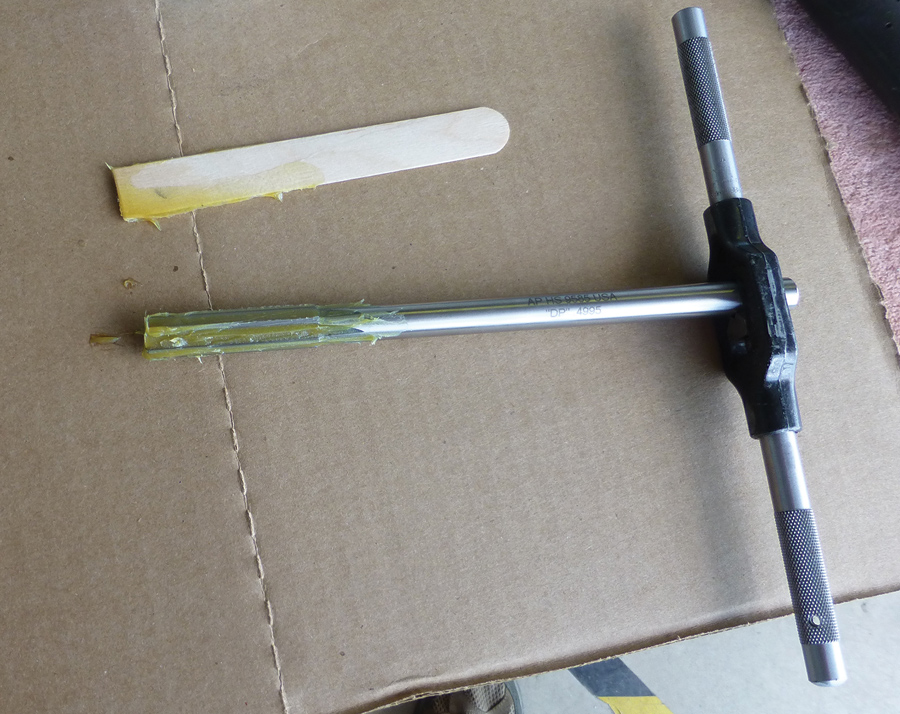
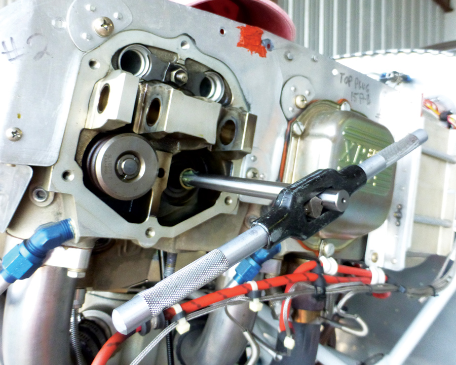
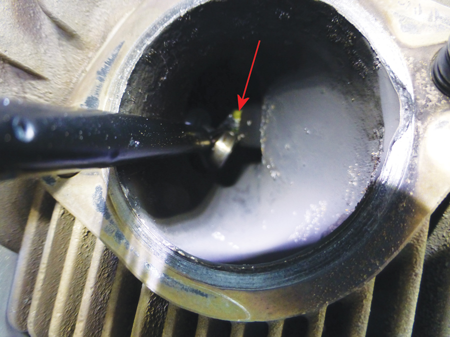
5. With the valve removed from the guide, the next step is to ream out the valve guide. The goal here is to go nice and slow, and also to prevent any contaminates that built up on the guide from being reintroduced into the engine. This is accomplished by putting axle grease (Aeroshell #5) onto the reamer (Figure 10). Chuck the reamer into a hand grip—you want to go very slow in order not to damage the guide (Figure 11). Ream the guide slowly, turning the reamer clockwise until the tip of the reamer can be seen through the exhaust port (Figure 12). In order to remove the reamer, continue to turn it clockwise and remove it from the guide. Be sure to appreciate all of the crud that comes out after you remove the reamer (Figure 13)!
6. The next step is to remove any contaminants that might have been left behind in the valve guide. My method for this was to push a small cloth rag lightly doused with carburetor cleaner (acetone or any other solvent should also work) down the guide with a dowel, and remove it through the exhaust port.
7. Using a cotton swab, I lightly coated the exhaust valve guide with some engine oil.
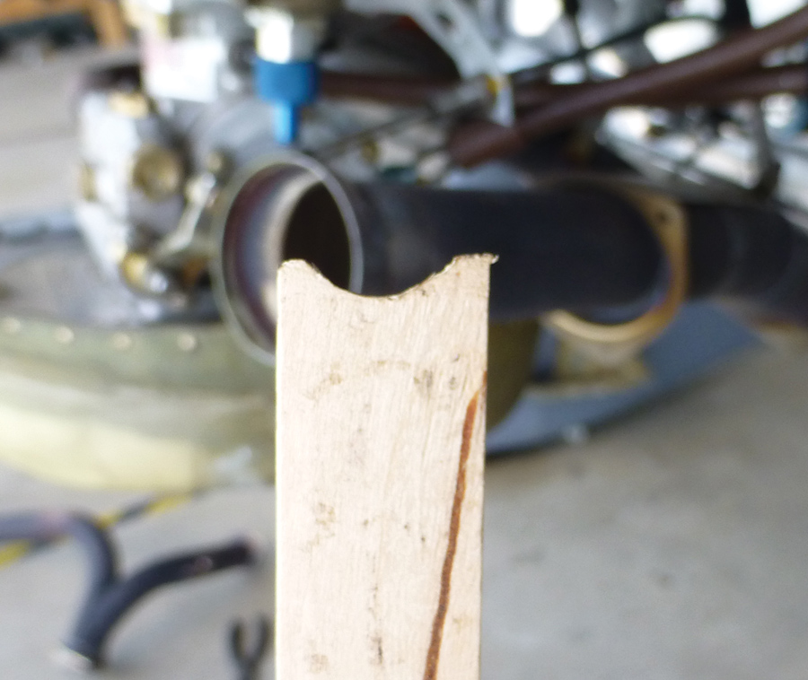
8. Now the fun part begins—reinstalling the valve into the guide! The concept of this is simple on paper: Insert a magnetic telescoping wand down the valve guide, grab onto the end of the stem and yank the valve back into the guide. Simple right? Well, it is that simple. However, the valve fits into the guide very tightly, and the alignment of the valve stem needs to be perfect to get it in correctly. I found the mechanical pick-up tool not to be strong enough to lift up the valve to get it aligned properly. The trick that worked for me was to take a wide Popsicle stick and file a “U” into one end of it (Figure 14). The Popsicle stick can then be used to lift up on the portion of the stem nearest the piston. With a little trial and error, it took me about 5 minutes to get the valve back into the guide. Once the tip of the stem is installed in the guide, the mechanical pick-up tool can be removed and the valve can be pulled fully into the guide.
I have read some stories of people using the piston to push the valve into the guide. While this has worked, it is not recommended by Lycoming because it could damage the valve and/or the guide. Just don’t do it. Take your time and prevent yourself from possibly pulling the jug!
Reassembling the Exhaust Valve
1. The first step in reassembly is reconnecting the valve stems to the valve springs. In order to do so, you need to make sure the valves are seated tightly to the top of the cylinder at TDC by using either the rope trick or with compressed air. With the valves fully seated, install the spring retainers, as well as the cap for the exhaust valve.
2. Use the spring compressor to compress the valve springs.
3. Install the keys. For my exhaust valves, the keys were not polarized. However, double-check if your keys are polarized and the proper orientation they should be in before installation. I found this to be a tedious process to get the keys in just right.
4. Install the cap on top of the exhaust valve stem.
5. With nearly every engine project I have ever worked on, the reassembly process is easier than the disassembly. Up to this point, my old philosophy has held true. Unfortunately this is not the case with this job. The reason being is the hydraulic lifters expand and fill with oil. This makes installing the rocker arms an impossible task without first compressing the hydraulic lifters. There are two main ways to reduce the size of the lifters:
a. Remove the lifters. This involves removing the pushrod shrouds, then using some safety wire to fish out the lifters. Using a toothpick, you can depress the center of the lifter to relieve any pressure in the lifter. Reinstalling the lifter, pushrod shroud, and pushrods now gives you the ability to reinstall the rocker arms and rocker arm shaft.
b. Compress the lifters. I figured there needed to be an easier way by compressing the lifters. I tried and failed at a number of experiments, which ranged from using Irwin soft plastic clamps to using the force of my hand. The method I came up with that worked extremely well was to use the engine to compress the lifters! While with the lifters full of oil I couldn’t install the rocker arm shaft, I could install a slightly smaller wood dowel in place of the rocker arm shaft. I then rotated the engine so the valve I needed to compress the lifter for was open. This process used the springs of the valve to exert force on the lifter to compress it (it took anywhere from 1-10 minutes per lifter). Once the lifter has been compressed, you need to work fast. These guys expand back to their full size rapidly! It would be ideal for this portion of the job to involve two people—one person to exert hand pressure on the top of the rocker arm to keep the lifter compressed, while the other person rotates the propeller so both valves are closed. While it can be done, it can be quite awkward to accomplish this solo. With the lifter compressed and the valves closed, act quickly to insert the rocker arm shaft. Be prepared to repeat this process and not get too frustrated when it doesn’t go right the first, second or fifth time (Figure 15)!
Figure 15: As the cylinder nears TDC, the camshaft is exerting maximum force against the valve spring. Let it rest here for a few minutes while the hydraulic lifters compress (A). Note the wood dowel in place of the rocker arm shaft (B).
Of course, you can always compress the lifters the way Lycoming intends, by removing the push rod tube, removing the lifter, disassembling it, and cleaning out the trapped oil. This does take some training and time, but avoids the need for brute force.
6. If you dropped the exhaust, now is a good time to reinstall it. Remember to replace the exhaust gaskets (if needed), use anti-seize on the stud threads (not too much, just a dab!) and torque the nuts down with new lock washers. For my IO-360, the proper torque value is 180 inch-pounds. [Corrected.]
7. Reinstall the spark plugs with new washers (or annealed old washers).
8. Reinstall the valve covers. I learned the hard way on this project not to over-torque the screws with silicon gaskets. On my first attempt I ruined all four gaskets using my German torque wrench, gutentite (Good and tight!). After researching this some more, the only spec I could find on torquing valve covers with silicon gaskets was from ECI (ECI Service Instruction 03-3) which specifies the following:
a. Clean the surfaces in contact with the gasket. Both surfaces must be clean of oil and debris.
b. Install the silicon gaskets dry. Do not use any sealant, oil or adhesive products.
c. Torque the screws to 25 inch-pounds (cold engine) or 20 inch-pounds (warm engine—100+ F).
d. Re-torque the screws after the engine has warmed above 100F to 20 inch-pounds.
I still found 25 inch-pounds to be too tight. I ended up using much less—8 inch-pounds with perfect results.
With the engine back together, it’s time to do a test flight. Before you do so, pull the prop through and check the compression in each cylinder and make sure no foreign debris ended up in any cylinder. You don’t want to find this out with the starter!











the proper torque value is 180 foot-pounds. on the exhaust??? For some reason I do not think that this is correct?
He will break every stud off retorquing to 180 ft lbs.
Thanks, we’ve corrected it to say 180 inch-pounds.
Lycoming SSP1776 shows torque for 5/16 to be 204-228.
On the superior experimental engine it may be different (I don’t think so) but on Lycoming paralell valve engines, the rocket arms look very similar and can inadvertently interchanged but they are not the same. The intake rocker arm has a gravity feed “funnel” and hole that provides oil to the rocker shaft area while the exhaust rocker is not externally drilled and provides oil under pressure to the shaft. Worth checking.
Edit: that’s inch pounds, not foot pounds by the way…
The most common sense article I’ve read on this scenario.
Thank You.
Doran Jaffas
N625MS
I don’t see Marvel Mystery Oil or TCP in Service Letter No. L197A dated January 19, 1988, nor in Service Instruction No. 1070AB dated April 8, 2020. Are we looking at the same pubs to endorse using either of those additives?
I have done this a few times before, sometimes you need to drop the valve into the cylinder and manipulate it out through the lower spark plug hole, and scrape the carbon off the valve stem. polish with fine (#400) grit wet&dry paper and use a mechaincal finger to manipulate the valve back into the guide after reaming. It’s actually quite easy once you have done the first..