Last month we discussed aspects of light aircraft design and how the fuel system plays into the overall picture. The designer determines how much fuel the aircraft needs to carry to meet customer needs and how best to locate the fuel considering the sometimes-conflicting requirements of handling qualities. This includes minimizing cg travel as fuel is consumed; how the inertia of fuel affects the dynamics of the airplane in pitch, roll, and yaw; how the mass of fuel and its location relative to the axis of torsion of a wing or stabilizer can affect the flutter speed of the aircraft; and finally, how to configure the airplane so that fuel is safely contained, even in the event of a crash. The introductory article also included diagrams of two typical light-aircraft fuel systems that show all of the separate components in the overall design.
Having a good grasp of the fuel system in whole, let’s narrow the focus and look at the fuel system part by part.
Fuel System Detail Design
Following the path of the fuel from the point of entry into the system past each of the various fuel system components until it finally enters the engine, each part of the fuel system will be discussed and the design requirements applicable to that component will be reviewed. A homebuilt aircraft is not strictly required to meet any design standards or requirements, but the successful kit aircraft designs meet many of the same criteria that a certificated light aircraft must meet.
There is a great deal of similarity in fuel systems between different aircraft, so the components that are common to every fuel system will be reviewed before discussing components that are unique to certain systems.
Fuel Fill Opening and Cap
Even something as seemingly simple as the fuel fill opening and filler cap have a number of design requirements beyond simply being a sealable opening where fuel is introduced into the system. Some amount of fuel is spilled nearly every time an aircraft is refueled. Spilled fuel is not only a fire hazard, but the fumes are nauseating and unhealthy for humans to breathe. For this reason, the tank and cap must be designed to prevent spilled fuel from entering the fuel tank compartment or any part of the airplane other than the tank itself. This means, of course, that the fill opening cannot be located inside the passenger compartment. Most aircraft have fill openings located such that spilled fuel runs more or less harmlessly off the wing or fuselage. Some aircraft, however, must utilize a scupper constructed around the fuel fill opening to drain away any spilled fuel (see Figure 1).
To minimize the likelihood of someone putting the wrong fuel in the wrong airplane, fuel fill openings must be marked at or near the filler cap with the required fuel type (avgas, mogas, jet) and the minimum fuel grade. The inside diameter of the filler opening for airplanes with engines requiring gasoline as the only permissible fuel must be no larger than 2.36 inches. For airplanes with turbine engines, the inside diameter of the fuel filler opening must be no smaller than 2.95 inches. This is to prevent fueling of a gasoline engine aircraft with jet fuel.
How many pilots have either failed to properly secure a fuel cap (or even left a fuel cap behind!) after refueling? For this reason, another fuel system design requirement is that siphoning of fuel (other than minor spillage) may not result if the fuel filler cap is improperly secured or left off altogether. Figure 2 shows the Fairchild 24’s classic “art deco” style fuel cap, which is tethered to the filler with a short chain. Tethered fuel caps are a mixed blessing as the benefit of never leaving a cap behind at the pump is largely offset by the damage done to the finish when the cap is left unsecured. At the very least, the thumping noise will get the pilot’s attention and prompt a precautionary landing before much fuel is lost.
Fuel Tank
The tank is the place where fuel is stored until it is consumed by the engine and is the first place where particle contaminants and water are separated from the fuel. Because water and particle contaminants are heavier than fuel, they will settle to the bottom of the tank. Each fuel tank is required to have a drainable sump with an effective capacity, in the normal ground and flight attitudes, of 8 fluid ounces or, if the tank is larger than 25 gallons, 0.25 percent of the tank capacity. The tank design must allow any hazardous quantity of water to drain from any part of the tank to its sump with the airplane in the normal ground attitude. By draining a sample of fuel from each sump and visually inspecting it, the purity of the fuel in the tank can be assured before leaving the ground.
Fuel tanks fall into three basic categories: integral fuel tanks, rigid removable tanks, and non-rigid removable or “bladder” tanks.
A tank is called “integral” when it is simply part of the aircraft structure that has been sealed to contain fuel. This type of tank provides the highest volume of space available with the lowest weight. It is also considered the least crashworthy of the three types of tanks. Integral fuel tanks must be able to withstand the pressure developed during the maximum limit acceleration of the airplane when fully filled with fuel with the critical limit structural loads simultaneously applied. Integral fuel tanks must also have means for interior inspection and repair. Often this is accomplished by making the integral tank removable as is the case with the Piper PA-28, PA-32, and the RV-4, -6, -7, -8, -9, -10, and -14. Otherwise, access openings in the skin are the means of gaining access for inspection and repair (see Figure 3).
Figure 3: The integral tanks of this Cirrus SR22 are accessed via removable covers on the bottom of the wing.
A rigid removable tank is a separate fuel container that is supported by the airframe but, because it does not carry any structural loads, is not considered integral. Rigid removable tanks are held in place by screws or some type of strap arrangement. Tanks of this type are often made from sheet metal and are assembled by welding or riveting. Rotationally molded plastic tanks have become common in later homebuilt designs and are considered good for crashworthiness as the plastic is both puncture resistant and can deform without spilling fuel (see Figure 4). The beauty of a rigid removable tank is the convenience of being able to remove a tank for repair or replacement.
A non-rigid removable or “bladder” tank, as the name implies, is made out of a flexible rubberized material and requires continuous support from the airframe. The bladder is installed in a special bay through a small access opening. Being flexible, the bladder must be attached to the structure with clips or other fasteners. It must lay smooth in the bay because any wrinkles on the bottom surface will prevent water or particle contaminants from migrating into the sump. A bladder tank is considered to be the most crashworthy of all tank types. The Beechcraft Bonanza and Cessna 180 are examples of light aircraft that use bladder tanks, but they are rarely (if ever) used in homebuilt aircraft. Given the crashworthiness advantages of molded plastic tanks, it is doubtful that any new aircraft will be developed that use bladder tanks.
Regardless of the type of construction and capacity, each fuel tank must be able to withstand the vibration, inertia, fluid, and structural loads that it may be subjected to in operation. With some variation, each fuel tank must withstand a positive internal pressure of 3.5 lb/in2. Fuel tanks must be designed, located, and installed so as to retain fuel when subjected to upward acceleration of 3.0 G (4.5 G if acrobatic category), forward acceleration of 9.0 G, sideward acceleration of 1.5 G, and downward acceleration of 6.0 G.
Figure 5: Fuel capacity for certain versions of the Sukhoi 26 limits flight time to less than an hour.
The total useable capacity of the fuel tanks must be enough for a “reasonable” amount of flight time. Different light aircraft design standards call for different minimum fuel capacities ranging from 30 minutes to 1 hour at the fuel consumption of the engine at maximum continuous power. Most aircraft designers will provide fuel capacity sufficient for at least 2 hours of operation at maximum continuous power, but the designer of a competition aerobatic aircraft may want to minimize fuel capacity for reasons of safety and performance. For example, the fuel capacity of a standard Su-26 (see Figure 5) is only 16.7 gallons. The Sukhoi’s 360 hp engine will easily drink that amount of fuel in less than an hour.
Figure 6: The Piper Comanche fuselage is lower than the bottom of the wing, which keeps the tank from becoming ruptured in the event of a gear-up landing.
For aircraft with retractable landing gear, each tank must retain fuel in the event of a gear-up landing on a paved runway (see Figure 6). The tank must also retain fuel in the event that one landing gear leg is collapsed and the other landing gear legs are extended. In such cases, the possibility that an engine mount could tear away and rupture a fuel tank must also be considered.
For fixed-landing-gear aircraft, each fuel tank must be designed to retain fuel in the event that a landing gear leg fails or is torn away (see Figure 7).
Figure 7: Bottom view of a PA-28 left wing showing the separation between the landing gear and the fuel tank.
Fuel tanks may be located in the fuselage, wing, or even in the empennage, but with certain limitations. No fuel tank may be on the engine side of the firewall. There must be at least one-half inch of clearance between the fuel tank and the firewall. No part of the engine nacelle skin that lies behind a major air opening from the engine compartment may act as the wall of an integral tank. Fuel tanks must be isolated from personnel compartments by a fume-proof, fuel-proof enclosure that is vented and drained to the exterior of the airplane. Air ventilation and fluid drainage must be provided in each fuel tank compartment and in each compartment adjacent to an integral fuel tank to prevent accumulation of flammable fluids and vapors.
Much like rubbing a balloon against your cat, the movement of fuel against the interior of a tank creates an electrical charge. To avoid buildup of electrical charge and possible sparking, each fuel filling point must have a provision for electrically bonding the airplane to the ground fueling equipment. For a metal aircraft with metal tanks, this is accomplished by grounding to practically any part of the airframe or even the engine. But for a non-metallic aircraft and/or non-metallic fuel tanks, an important detail that the designer must provide is a means to dissipate static electricity.
Figure 8: The fuel level in this Just Aircraft SuperSTOL is shown directly via a transparent sight tube.
Fuel Quantity Indicator
The pilot must have a means during flight to determine the quantity of useable fuel remaining in the tank. The simplest and least failure prone quantity indicator is a section of transparent tube or a small window that allows the pilot to directly see the level of useable fuel in the tank (see Figure 8). The next simplest direct quantity indicator is a float connected to a rod that protrudes from a hole in the filler cap (see Figure 9). Other quantity indicators have a float attached to a mechanical indicator that is mounted directly to the tank. The use of these direct-reading indicators is possible only when the fuel tank is located immediately adjacent to the cabin.
Figure 9: Baby Ace filler cap. A float attached to a piece of piano wire passes through the cap to indicate fuel quantity. The tube that is bent to face forward is the vent.
When use of mechanical indicators is either not possible or not desired, an electric quantity indicator is most commonly used. The most common fuel level sending unit consists of a float attached to an arm that is in turn attached to the wiper on a variable resistor mounted inside the tank (see Figure 10). The sending unit is wired to an electronic gauge in the cabin calibrated to display the amount of usable fuel in the tank corresponding to a particular electrical resistance. This type of quantity indicator is almost universally used on automobiles and has proven to be both sufficiently accurate and reliable.
Another type of electric sending unit consists of one or more capacitors in the tank. Because the capacitance varies according to how much fuel is in the tank, it is possible to sense fuel level without having any moving parts in the tank. A further advantage of a capacitive sending unit is that the quantity indication does not change as much with aircraft attitude as with other types. The major disadvantage of a capacitive sending unit in an aircraft that uses gasoline is that avgas, mogas, and mogas with ethanol each have different dielectric constants; this means that the system can be calibrated for only one particular gasoline type and will not be accurate if another type of gasoline is used.
Figure 10: Electric “float type” fuel sending unit as installed in an RV-7 fuel tank. Note the coarse mesh fuel outlet strainer in the lower right corner of the tank.
Vent
This allows air into the fuel tank to replace the volume of fuel consumed by the engine and to allow for equalization of pressure as the aircraft climbs or descends. For some fuel systems, venting can be accomplished by simply putting a tube (see Figure 9) or relatively small hole in the filler cap. For most fuel systems, a separate vent line leading from the top of the tank to some discharge point is used. Unless an expansion space equal to at least 2% of the fuel volume has been designed into the fuel tank, the vent must discharge clear of the airplane, but for the sake of practicality, all vents should do so.
Each fuel tank must be vented from the top part of its volume so that even when the tank is full of fuel, air can move freely in and out with changes in fuel level, air pressure, and temperature.
Each vent outlet must be located and constructed such that the possibility of it becoming obstructed by ice or other foreign matter (dirt, insects, etc.) is minimal. This is accomplished in a variety of ways. Many strut-braced high-wing aircraft meet this requirement by placing the vent outlet directly behind the strut where it is still easily inspected, but is protected from becoming obstructed by ice or insects or even a bird strike (see Figure 11). This location also protects the vent from people who like to bump their heads on such things. Other aircraft have unshielded vent outlets, but they are located on the airframe where ice is unlikely to accumulate such as on the bottom of the fuselage or some distance aft from the leading edge of the wing (see Figure 12). The most effective strategy for protecting the vent outlet from icing is to place it in a recess on the bottom of the wing (see Figure 13).
Figure 12: The vent outlet on a PA-28 protrudes from the lower surface, but is quite far aft on the wing.
There may be no point in any vent line where moisture can accumulate with the airplane in either the ground or level flight attitudes unless drainage is provided. Any vent drain valve installed must be accessible for drainage.
No vent may terminate at a point where the discharge of fuel from the vent outlet will constitute a fire hazard. For example, placing a fuel vent directly in the exhaust stream or in a location where lightning is likely to attach to the airframe would not be considered an optimum choice.
Each vent must be constructed to prevent siphoning of fuel during normal operation. For acrobatic category airplanes, excessive loss of fuel during aerobatics, including short periods of inverted flight, must be prevented. It must also be impossible for fuel to siphon from the vent after returning to normal flight.
Vents must be arranged to prevent the loss of fuel, except fuel discharged because of thermal expansion, when the airplane is parked in any direction on a ramp having a 1% slope.
Figure 13: Light aircraft that may encounter icing conditions protect the vent outlet by placing it in a recess on the bottom of the wing.
Fuel Outlet Strainer
To reduce the risk that foreign objects or other fuel contamination can enter the fuel line and impede or even totally stop the flow of fuel to the engine, each tank outlet is required to be protected by a course mesh strainer (sometimes called a “rock filter”). See Figures 10 and 14.
Figure 14: Fuel outlet strainers are typically threaded into a pipe thread fitting built into the tank.
Figure 15: Each Cessna 172 fuel tank has two outlets to ensure that fuel will flow in all flight conditions.
Because each fuel outlet must be protected, an aircraft like a Cessna 172, which has two tanks, each with two outlets, must have four strainers (see Figure 15).
For reciprocating engine powered airplanes, the strainer must have 8 to 16 meshes per inch so only relatively large particles will be captured by the strainer. Other strainer design requirements are that the clear area of each fuel tank outlet strainer must be at least five times the area of the outlet line, the diameter of each strainer must be at least that of the fuel-tank outlet, and each strainer must be accessible for inspection and cleaning.
Looking ahead, this article series will cover the functionality requirements for fuel lines, fuel pumps, shut-off and/or selector valves, and fuel filters. Also covered will be the hows and whys of header tanks, fuel returns, and negative-G flying.


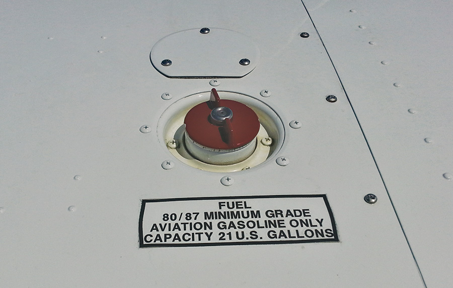
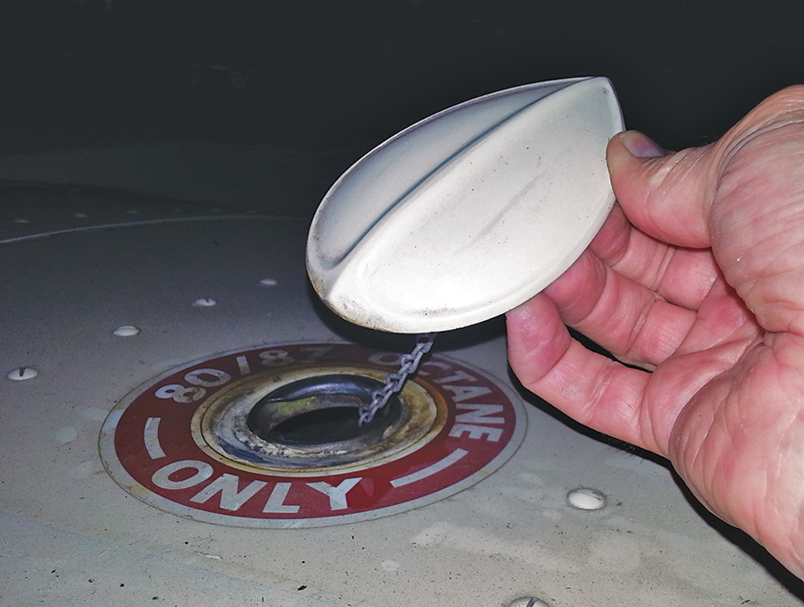
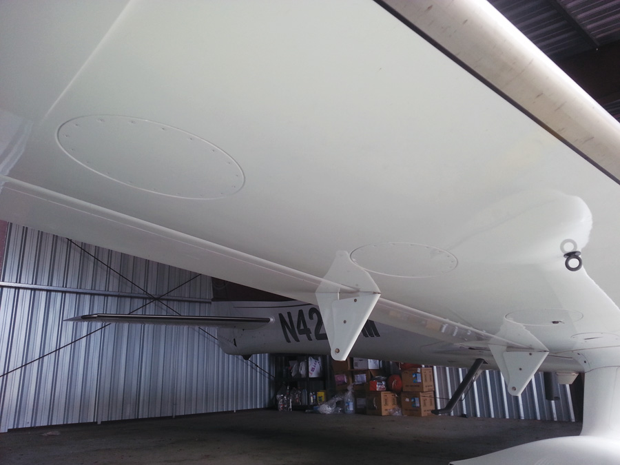
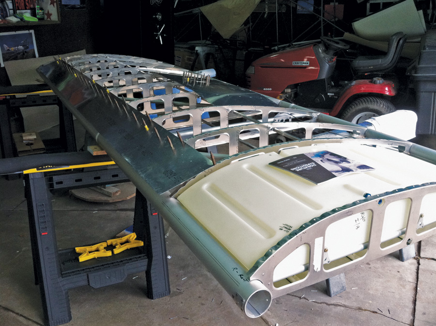



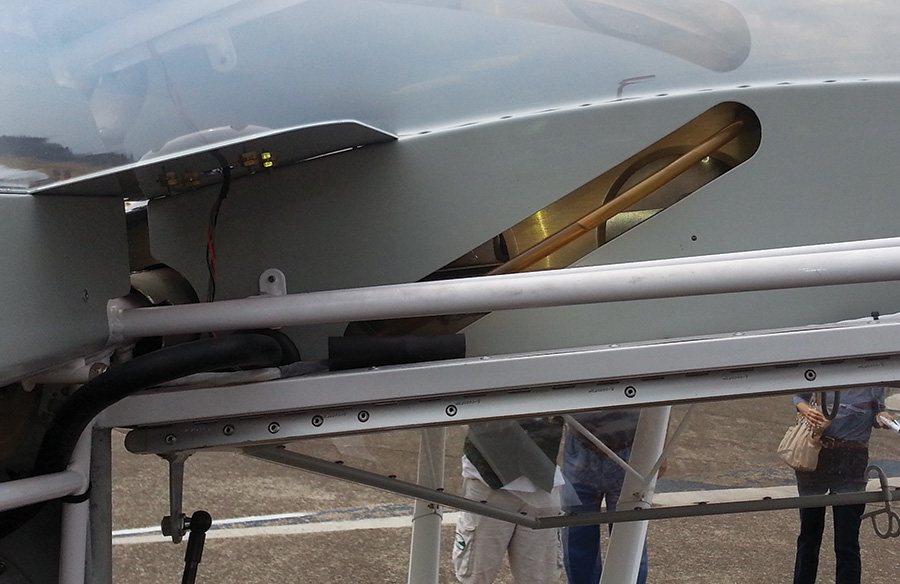
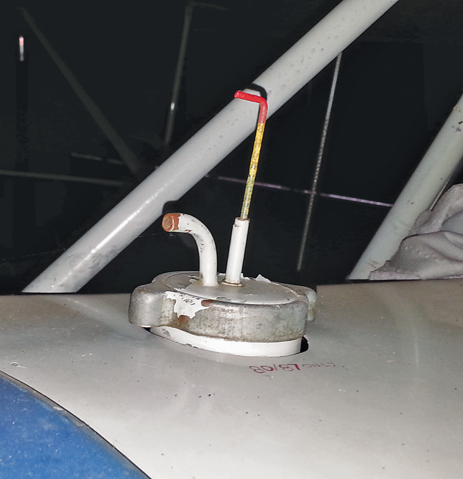
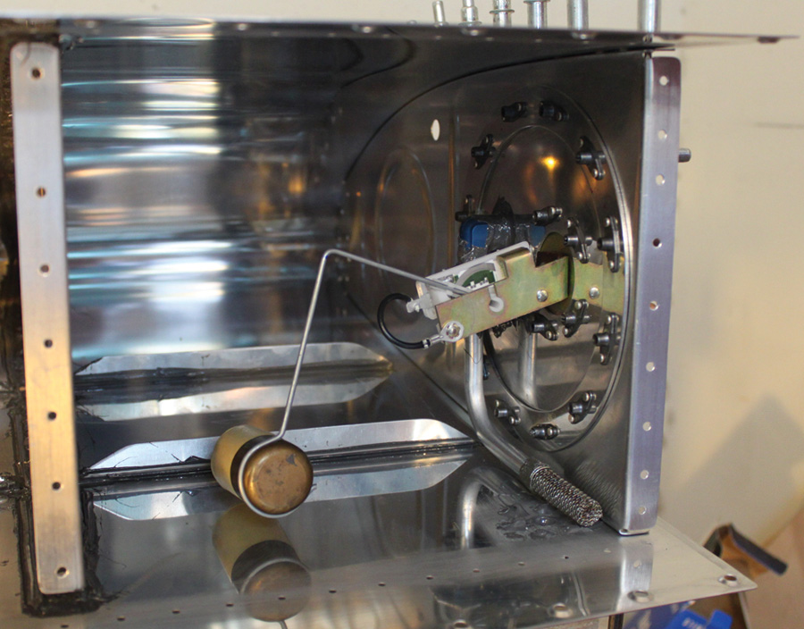
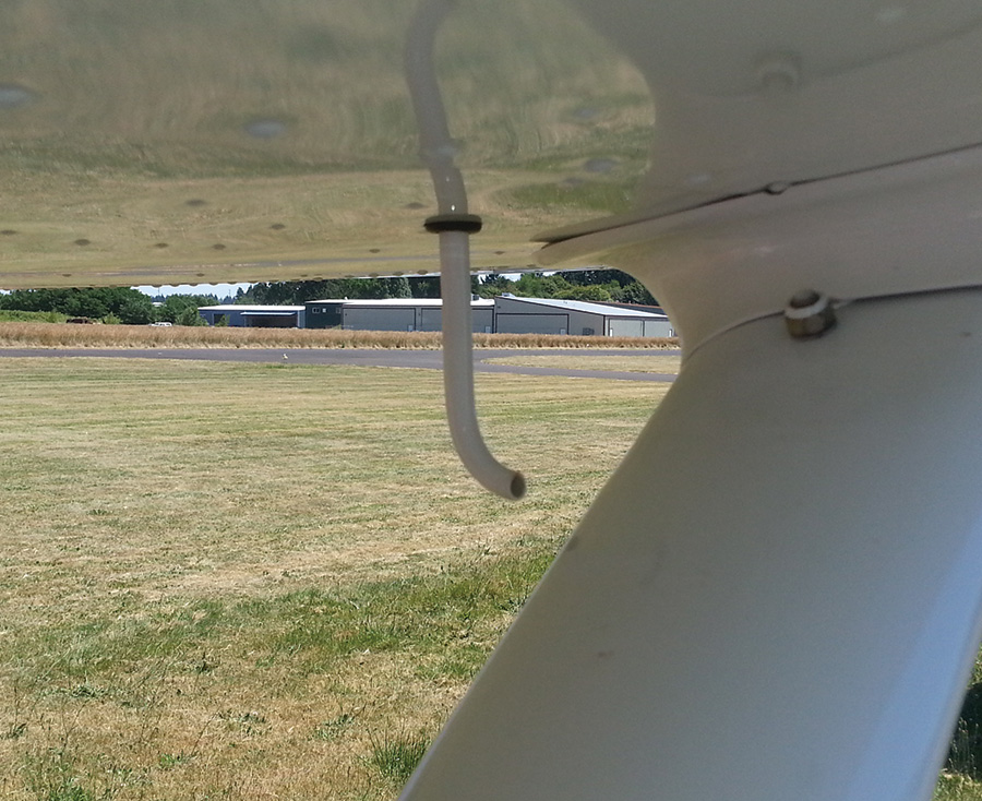
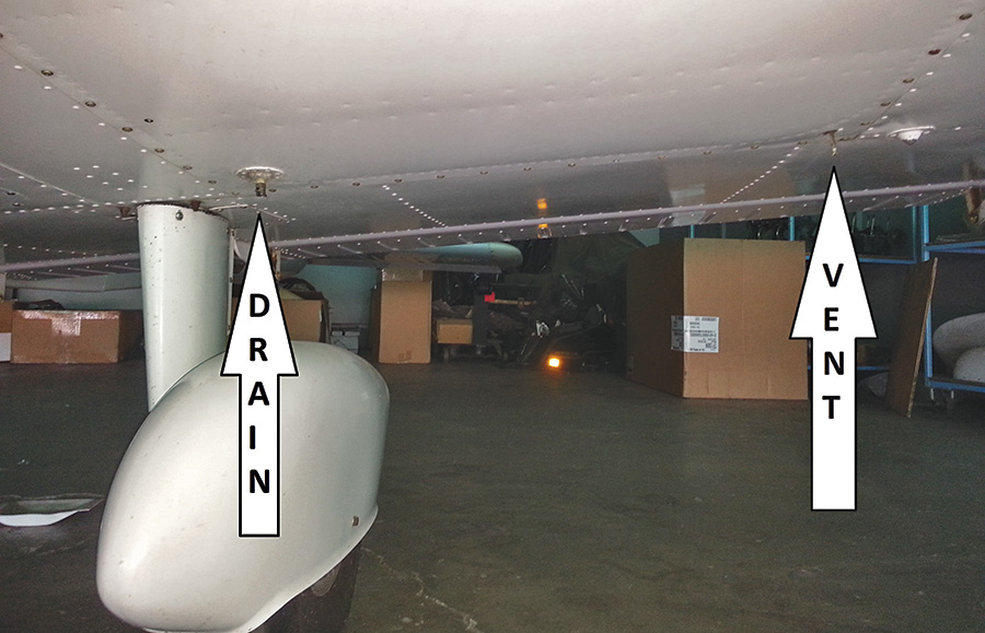
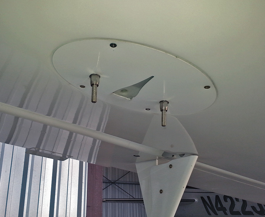

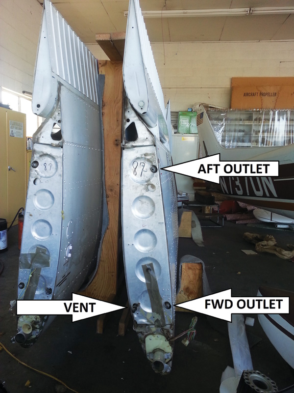







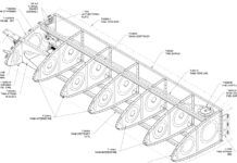




Figure 14: Fuel outlet strainers are typically threaded into a pipe thread fitting built into the tank.
Where can I purchase this please
Regards
Brian
Aircraft Spruce sells them: https://www.aircraftspruce.com/catalog/appages/fingstrainers.php?clickkey=18727
Good day , can i know how much force or pressure will the fuel tank experience with a G-force of 4G in newtons or pascal please?
i am modelling a fuel tank in ansys, and i want to know how much force should i include in my analysis of how much force or pressure should the fuel tank withstand considering 20.7 gallons of fuel with 4 G.