
I harbor two writers within. A technical writer who favors brevity and a creative writer, an essayist, who wants to engage your senses and take you places. At the onset of this monograph I asked both writers how we could make bending thick pieces of aluminum exciting. The answer came swiftly: By making it not exciting. That is, by making it so mundane that someone’s fear of the process is allayed.
Every homebuilt airplane has some need that can scare a builder away or stall their progress. A person attracted to the simplicity of a wood-and-fabric aircraft may be intimidated by the few welded brackets they require. Someone who embraces fiberglass may flinch at the fuel system. Someone with no metal-building experience (me, for instance) may need to invest heavily in bandages and suck it up if they want to build an all-aluminum airplane.
That’s just what I did and, it turned out, I did it well enough to have accidentally built a 21-year career helping other builders, many novices themselves, over the proverbial humps. My strength, I feel, lies in an ability to explain techniques to builders (builders whose eyes are already wide, wet and worried) without using frightening words like ream, tangent or burnish. Additional strengths include being a cheapskate who finds the least expensive way to get a job done and my innate ability to make things mundane. (That may not have come out quite right.) Here, I strive to make bending 6061-T6 aluminum parts ranging from about 1/8-inch to about 1/4-inch thick as mundane as possible. I’m confident this method can be adapted to steel and other aluminum alloys, but all of my experience lies with 6061-T6. Now, let’s get crackin’.
Let’s Not Get Crackin’
Nicks and scratches on parts (the frightening term for them is “stress risers”), particularly on the edge of a part, are breeding grounds for cracks. They are like the perforations on toilet paper. They enable stress to crack the part. Needless to say, bending a material induces considerable stress. Therefore, imperfections on the part, particularly near the bend, must be removed prior to bending. This is often called deburring, a fancy word for filing and sanding.
As a rule of thumb, any scratch or nick that can be felt with a fingernail must be removed. My personal standard is to remove anything I can see. (For that I was admonished, “You’re not building jewelry!” And I had to agree. I didn’t know a single piece of jewelry in which I could stuff my biology and pull up to 6 G’s.) I remove the worst marks on a part’s edge with files and sandpaper before finishing with a Scotch-Brite wheel or a generic version of a 3M Combi-S wheel, chucked in a hand drill. Deburring is worth every moment it takes to do a good job.
The Press
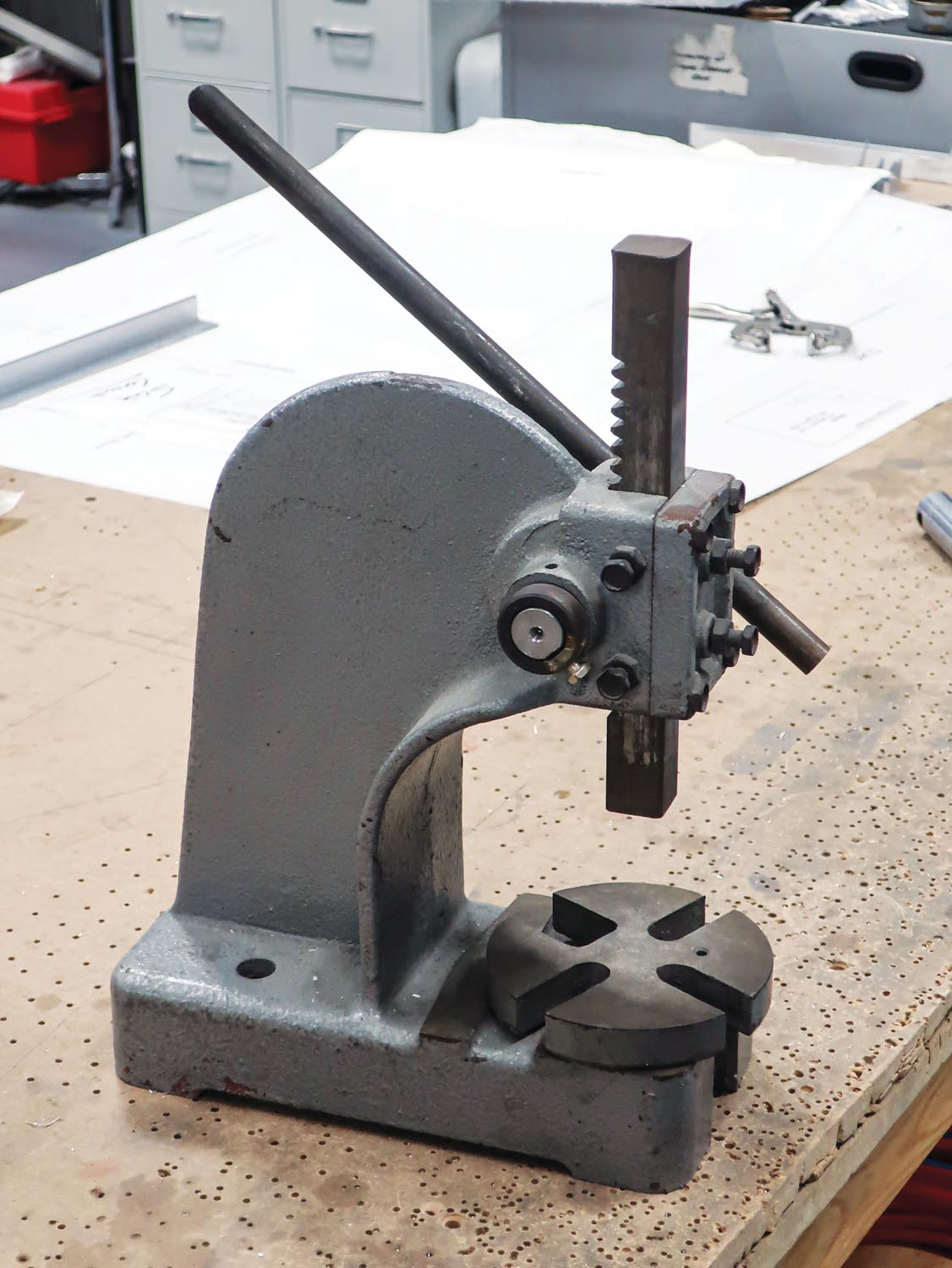
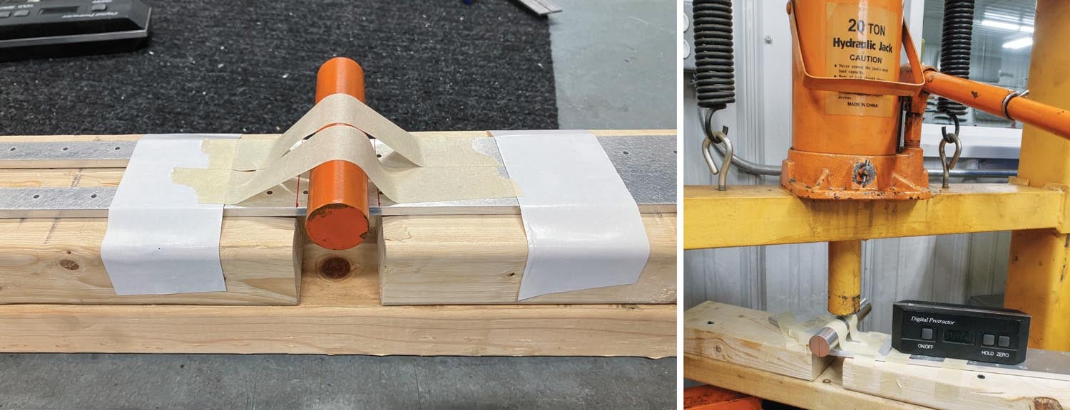
There’s no way around the need for a press. The best press is one you can borrow the use of. Barring that, a 1-ton benchtop arbor press can be purchased for under $100 and will generally handle 6061-T6 up to 3/16-inch thick. Success hinges on how much pressure you can exert and the length and angle of the bend. A wide or deep bend may prevent your success. I’ve bent 3/16-inch-thick 6061-T6 parts up to 2-1/2 inches wide and up to 35° with a 1-ton arbor press. Arbor presses come in various sizes, but get pricey as their capacity grows. If you need anything over 1 ton, and have an empty 20×20-inch spot on your shop floor, your money is best spent on a hydraulic H-frame press. They are powered by a bottle jack and can be purchased for under $200. Still, borrowed time on someone else’s press is the most cost-effective route for a builder with only a few parts to bend.
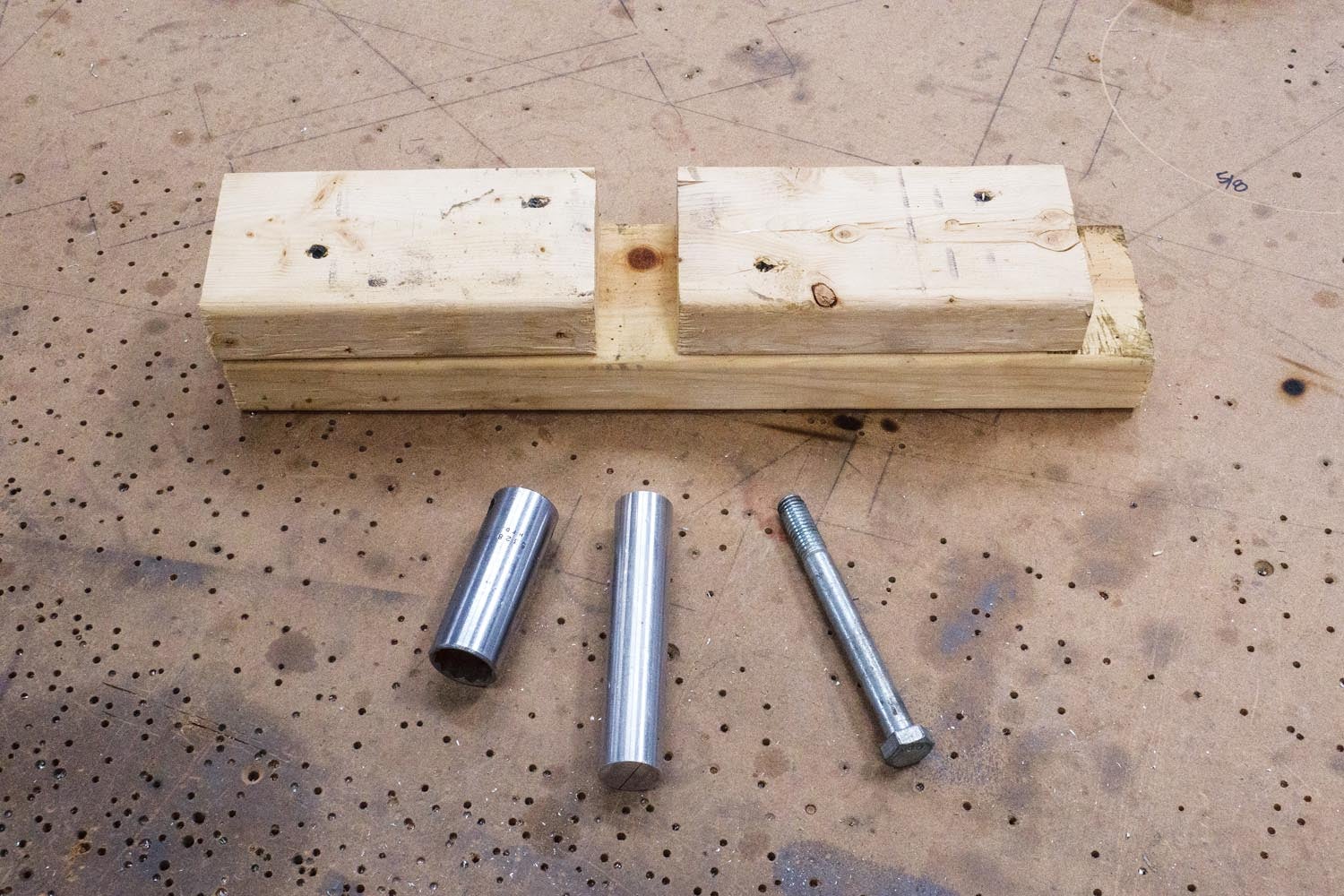
Building the Bending Fixture
I tried to find a word less intimidating than fixture because the question “Will I need to build fixtures?” is usually asked with an air of concern, but there isn’t one. Technically, what we’re building is a die. Let’s not ponder why. In this case, fixture is a $100 word for three 2×4 stud scraps held together by wood screws. Together, they form the base the part to be bent is secured to and supported by. It’s nothing more than a long 2×4 board to which two shorter pieces, separated by a calculated gap, are attached. The terms long and short are relative and the accompanying photos give an idea of what’s needed. What isn’t needed is overthinking.
The key to the fixture is having the gap between the two short pieces properly spaced for the part’s thickness and bend radius. Your project’s plans or manual should provide the bend radius for each part. The rest is simple math:
Gap = (Bend Radius x 2) + (Part Thickness x 2)
If I’m bending a 3/16-inch-thick part with a 1/2-inch radius bend, the math looks like this:
(1/2 inch x 2) + (3/16 inch x 2) = 1-3/8 inch
The gap between the boards is 1-3/8 inch.
With the gap established, the short boards can be squared and secured to the longer 2×4 scrap. I’m going to slip into technical writer mode and give you numbered steps for this.
- Use a square to draw a line across the wide face of the long 2×4. The line should be somewhat centered along the length of the board.
- Measuring from that line, draw another line across the board equal to the distance you calculated for the gap.
- Align a square-cut end of each board with a line on the long board and screw them in place. Make sure the screw heads are below the surface of the wood so they don’t scratch your part.
Radius Forming Tool
The bending fixture is only half of what’s needed to make the bend. The other half, the half that transfers the press’s pressure directly to the part, is called a punch. I won’t use that term here because it sounds blunt and damaging. I’ll call it a radius tool. For us amateurs, a radius tool can be a length of pipe, a steel or aluminum rod, a thick-walled steel tube, the smooth shank of a bolt, a deep well socket, etc. It only needs to be the correct diameter for the bend, long enough to overhang the part, smooth so it doesn’t mar the part and strong enough to withstand the pressure.
Remembering that bends are typically defined with a radius, and that diameter equals twice a radius, the diameter of your radius tool needs to be twice the bend’s radius. A 1/2-inch radius bend requires a 1-inch-diameter radius tool. A 1/4-inch radius bend requires a 1/2-inch diameter radius tool. Here’s a tip: If you use a socket for your radius tool, a 1-inch socket is not 1 inch in diameter, so don’t fall victim to a momentary lapse in reasoning.
Bringing It All Together on the Press
This is the hardest part and it’s not that hard at all unless you’ve had too much coffee. I’m going to use numbered steps again.
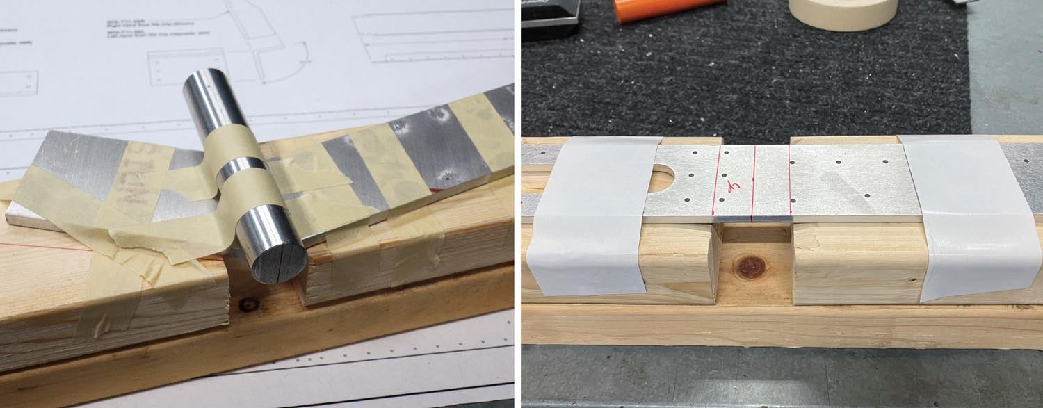
- Draw a line on the part to denote the center of the bend. On each end of the bend, extend the centerline down the edge of the part. These lines help align the part on the fixture and the radius tool on the part.
- Place the part on the fixture, centering the bend line over the gap. Measure to make sure it is centered.
- Tape the part to the form block so it maintains its position. Masking tape works well.
- Center the radius tool on the centerline on the part. This is the most fiddly part of the process but you want to get it right. If you get the radius tool crooked on the centerline the bend will be crooked. The centerlines you projected down each edge of the part will be helpful. Use tape to hold it in place.
- Place your completed multimedia sculpture in the press, centering the radius tool under the ram of the press.
- Bring the ram down into light contact with the radius tool.
- Let out a sigh. The fun begins now.
Bending the Part

All that’s left is to apply pressure to form the part to the correct angle. I’ve used any number of methods to measure the bend, but I’ve settled on using a digital level. It gives real-time feedback as I make a bend, which reduces the risk of overbending the part, and shows me quickly if I’ve compensated for the material’s springback. (More on springback in a moment.) What’s more, neither the part nor the fixture is disturbed throughout the process, reducing the risk of distorting the part. As the press’s pressure is increased, the level provides a real-time indication of half the bend angle, because it’s only measuring one side of the bend. However, we can assume that both sides of the part are forming equally, therefore a 30° bend will indicate 15° on the level. A 17° bend will indicate 8.5°. I think you see the pattern.
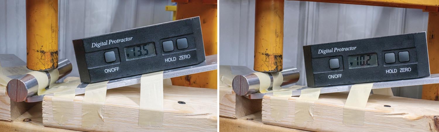
However, if you bend the part only to the target angle (for instance, 10° indicated for a 20° bend), a thing called springback will cause the part to relax to a lesser angle. Springback varies by material, material thickness, the length of the bend, the angle of the bend, the bend radius and, I’m sure, more. All you need to know is none of that matters because this is where using a digital level shines. When you reduce the pressure on the part, the level will show how much the part relaxed, or sprung back. If your goal is a 20° bend (10° indicated on the level) and the level indicates 8° after the pressure is removed, there is 4° of total springback. It’s safe to bring the pressure back up until the level indicates 12° and then release the pressure to see what the new angle is. If it indicates the target angle, you’ve nailed it. If not, continue to creep up on the bend until you reach the target angle. If you overshoot a few degrees (using this method it should be a few degrees at most, unless you grew impatient), contact the kit manufacturer for the proper remedy. Their response may indicate the part is good as is, can be safely unbent to the correct angle or must be scrapped.
Let me convert that mass of words into ordered steps:
- Place a digital level, aligned perpendicular to the bend, on one side of the part. Tape it in place if you think it may not stay.
- Zero the level’s readout.
- Slowly apply pressure until the level indicates half of the desired total bend or slightly more. The tape will break, but the pressure of the press will keep everything in place. Also, the wood base will get somewhat crushed, but that doesn’t impact the part or the procedure. The fixture is almost always good for more than one part.
- Slowly reduce the pressure so the ram retracts but remains in contact with the radius tool. The ram will keep everything in place in case more bending is required.
- Observe the reading on the level.
- a. If it is half the desired bend, you’re done.
- b. If it is less than half the bend, re-apply pressure to compensate for the material’s springback.
- c. If it is more than half the desired bend you’ve gone too far. Contact the kit manufacturer for guidance on correcting the issue.
Final Checks

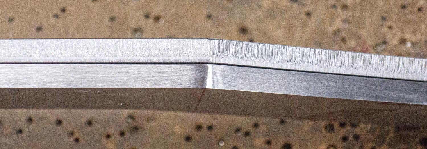
There are some things to inspect after forming a part. First, check the edges and the surface for cracks. Cracks on the edge are almost always fatal to a part. Cracks on the surface are also fatal, but what looks like cracks may be common, harmless “orange peel.” To check, sand and polish anything that looks like a surface crack. Orange peel will diminish or vanish; cracks will remain. If you have cracks, the usual causes are a failure to deburr the part and forming with a radius that is too small. In any case, contact the kit manufacturer for their input.
If no cracks are found, double-check the bend angle. I use a mechanical angle finder. If the angle is too shallow, carefully put everything back in the press and give it a tweak. If you bent it too far, contact the designer for guidance. If you are building a Sonex aircraft I’d tell you that any bend within 1° of what’s specified is perfect; often the leeway is more. I’d also tell you to round to the nearest degree. 9.4° sounds an awful lot like 9° or 10° to me and works just as well.
Check that the part was formed without a twist. It should go without saying that a thick aluminum part plays an important role of some type. You want it right. Finally, if the part is one half of a mirrored pair, or has a twin, compare the parts to see if they mirror or match each other as they are meant to.
It Was a Dark and Stormy Night
As a writer, I’m unfulfilled by what I’ve put down here. It’s not as brief as a technical writer would like and I’ve painted no compelling word pictures to satisfy the creative writer in me. What I have done, I hope, is take fear out of a task that more than a few builders fear. If I’ve done that, I’ve earned the space on which these words are printed. But just in case…
Major Payne fell from the perforated wreckage of his P-40. Pale fingers clutched a crumpled paper against his lead-ravaged breast. “I— I— drew…a mmmmap, sir.” His words were mixed with pride and liquid crimson. Before his effort could be acknowledged, his eyes stared into eternity’s abyss and death preserved his final expression: a faint smile.


This method works great. Bent the parts on my Sonex Onex, and they came out as perfect as I could expect. I spent more time making sure i marked things right and triple checking things before I finally made that first bend. But once I did it, and it came out perfectly and hit the exact angle easily (with some checking to make sure I didn’t overshoot), the following parts went far faster and came out perfect as well. This is a very useful method for people without the professional bending equipment.
Comments are closed.