OK, I’ll admit it. Back in the fifth grade my parents gave me a wood-burning set for Christmas. Now, they pretty much knew they had an incipient geek on their hands, but they had no idea that I would turn that wood-burning tool into a primitive soldering iron. Mom made sure I got the obligatory chemistry set, but Dad was bent on turning me on to the “he-man” stuff like burning wood for a hobby. My, how times have changed since the mid-’50s. Today (s)he-people are getting ready to throw people onto Mars. I wonder…will Artemis-Mars be designated an Experimental aircraft?
He-men (and she-women) have evolved. Soldering is an art that almost anybody can master with a few simple steps. And I double-dare you to call nearly every astronaut I’ve ever known some sort of a wimp because they all had to go through NASA solder school. (Did you also know that all astronauts must get their license to be ham radio operators to talk to young students in schools from orbit? W5LFL Owen Garriott started that tradition back in 1983.)
OK, we start with the basics. Soldering is nothing more than welding at a low temperature. It requires two metals that need to be joined, a filler metal that melts the two metals together and a compound (flux) of some sort that melts before the metals melt to clean the joint of impurities so the metals will form a firm bond.
Simple, right? And yes, it is. Instead of starting with a welding flame at several thousand degrees that intends to hold wing parts together, soldering does its work at a few hundred degrees intending to hold relatively small electronic parts together. Same process, same results.
Back a couple thousand years ago, the Romans decided that lead pipes would work well to pipe drinking water around the city. Workers working with these pipes used molten lead (plumbum in Latin) to join the pipes; these workers were called plumbers. I often reflect (as did the historian Edward Gibbon) whether the decline and fall of the Roman Empire was due to lead poisoning. Today, Pb is the chemical symbol for lead.
Some bright medieval alchemist found that the addition of tin to the lead (the symbol for tin is Sn—stannum in Latin) reduced the temperature at which the alloy of these two metals melted.
And so I bring you down to 2023 and solder as we know it. A mix of tin and lead reduces the temperature at which either of them melt, and we have a word, eutectic, which means the magic mixture of tin and lead that melts at the lowest temperature. This happens at a mixture of 63% tin and 37% lead at 361° F.
However, for whatever reason, the powers that be in the solder manufacturing industry decided in the early part of the electronic age that 60/40 solder (tin/lead) would be the standard. 60/40 melts at 376°, as opposed to 63/37 at 361°. This has created great hate and discontent in the industry. You can buy a relatively small amount (50 grams) of 63/37 for about $8 or a large amount (1 pound) for about $40. I bought a pound when I was about 30 and at nearly 80, there is half a pound left after a full life at this game. I prefer a relatively small diameter (0.032 inch) for electronic work.
There is one component of this solder process that we haven’t talked about yet, and that is flux. Nearly all components that you will be working with, whether resistors, capacitors or PC board traces, will be coated with solder. The solder will almost surely come with a core of flux, or liquid tree sap (rosin), as a central tube of rosin surrounded by an outer tube of solder. Rosin will melt well below the solder itself, so it will flow onto the joint below the solder metal.
Why rosin? Tin and lead, the primary coatings of electronic parts as well as PC board traces, oxidize. Yes, they almost immediately form a protective coat of oxide to prevent them from corroding. Solder, hot as it is, is not enough to break down this oxide layer, but pine sap dissolves it almost immediately. The oxide dissolves, the solder joins the parts, the oxide layer reforms and the solder joint cools—forming a new layer that prevents corrosion. Bingo.
The point: Never use solder with acid flux. Leave that to plumbers and water pipes.
Enough of the theory; let’s get on to making our first solder joint. In today’s world we rarely ever just solder two parts together themselves. Mostly we use a fairly thin (0.062-inch) sheet of fiberglass, usually coated on both sides with a very thin (0.00135-inch) layer of copper.
Anyway, the unwanted copper on the fiberglass (PC board) is etched away with some nasty chemistry, leaving only interconnecting “wires” and small “pads” with holes drilled through the copper and the fiberglass, and then the remaining fiberglass and copper is dipped into a molten solder bath to make the sandwich of fiberglass, copper and solder.
The components of the circuit are then soldered onto this PC board, and you have an electronic circuit all ready to put into a radio for your airplane.
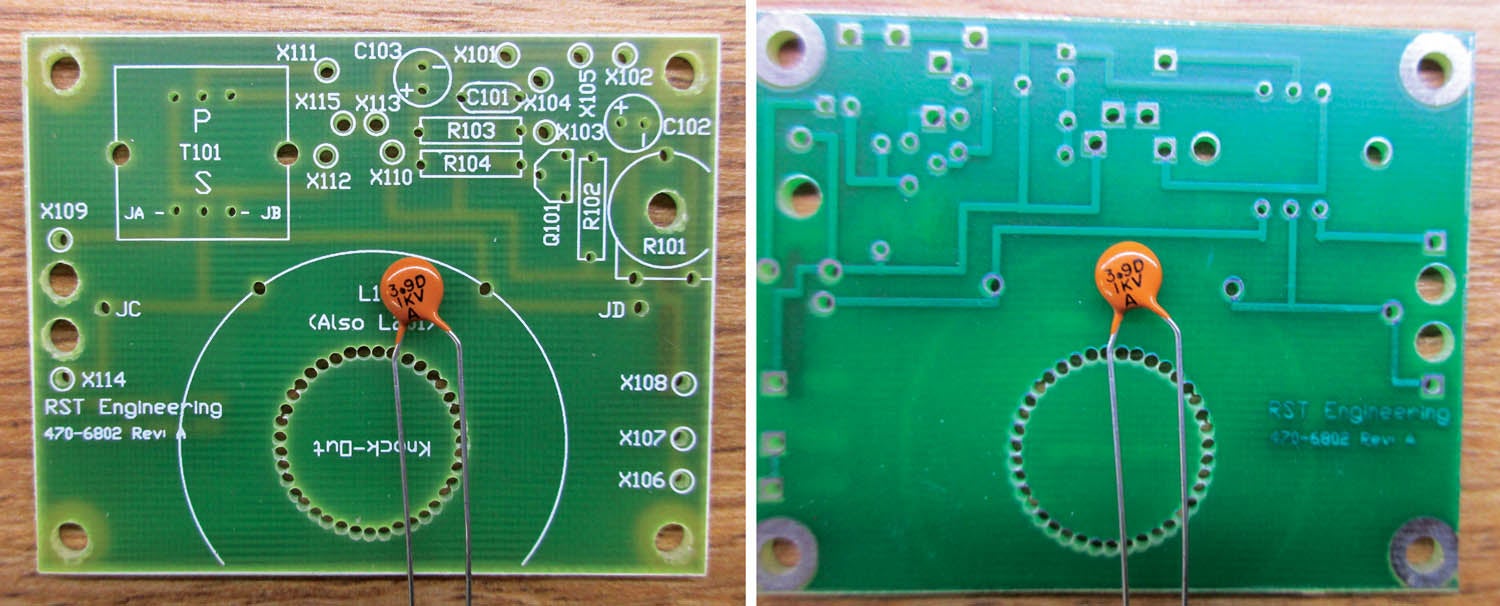
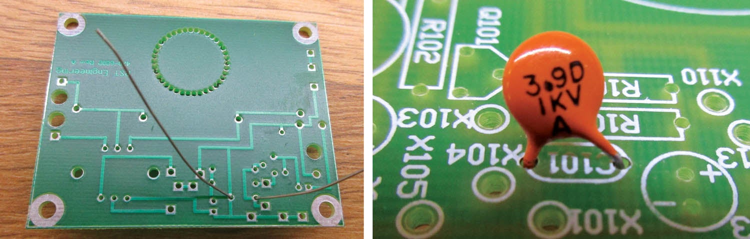
Shown in the photos is a typical PC board with a typical component that needs soldering to the board. I’ll do pretty much of a shorthand explanation with each step and a complete explanation in further columns.
The board is fiberglass with a green “solder mask” coating. The tiny silver holes on the back side of the board are copper pads, “tinned” (coated with solder), and you can see the light traces, which are the copper wires interconnecting the pads.
Even though the PC board and the disk ceramic capacitor to be soldered are both bright tinned (free of corrosion), and even after being sealed in “someday” boxes for 25 years, if they were corroded or dirty we would have to clean them before soldering them together.
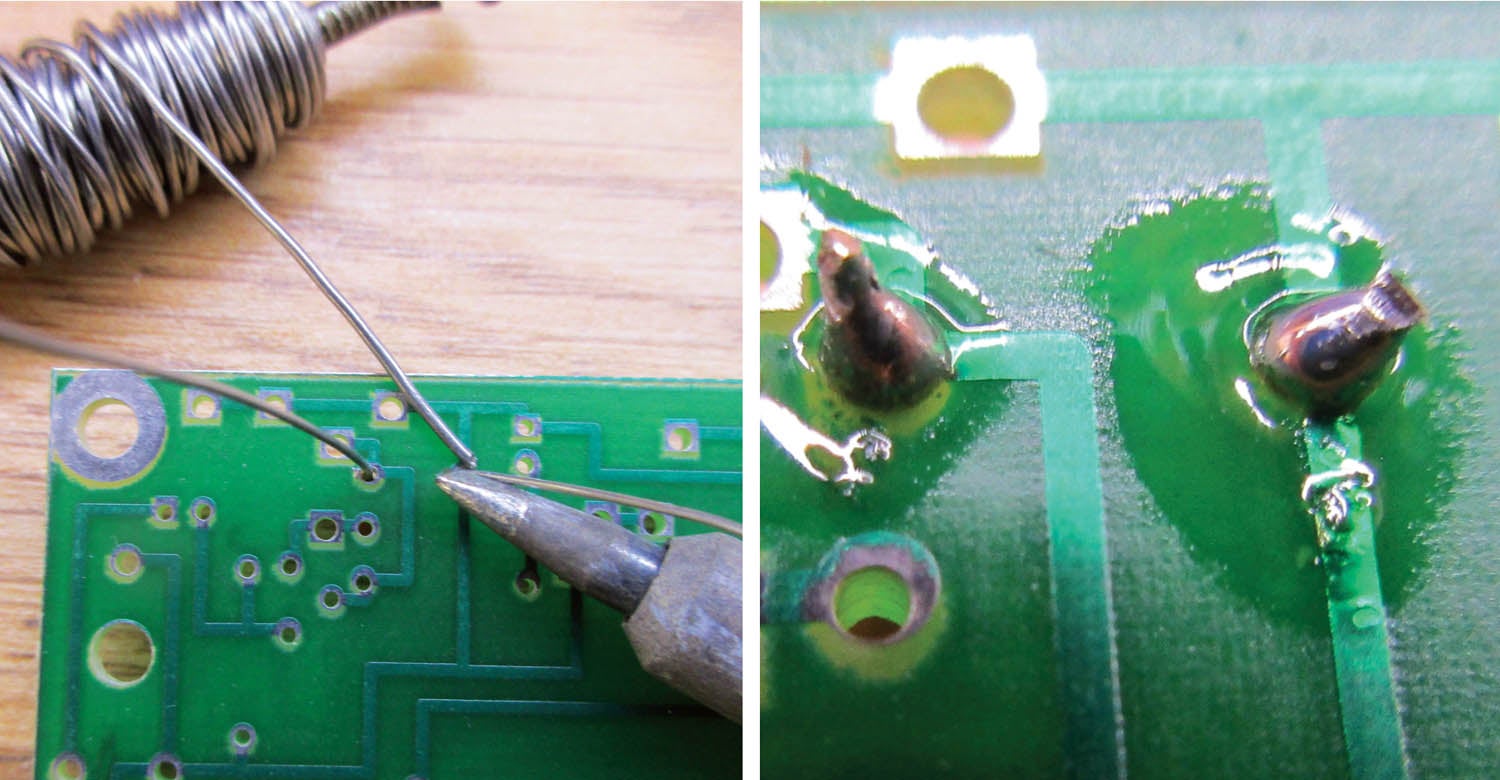
So it comes down to a hot soldering iron on the right, a roll of solder on the left, and behold, a perfect solder joint.
Of course, there is much more to it than just that. And you will get much more of that in future columns. Until then…stay tuned…


Learn something everyday. Didn’t know that the flux was pine sap ! But is soldering simply low temp welding ? I always thought that the difference between welding and soldering was the fact that welding involved melting the two parts being joined, rather than coating them in a solder
In soldering electronic parts, the copper leads are already coated with a thin coat of solder so you are using a filler rod of solder, melting both the filler AND the solder on the part, so in essence, you are melting the part with the filler rod. I suppose I could have gone into a long song and dance about “welding” is not melting the copper base metal of the part but the solder outside coating, but that seemed to me to add confustion to the process. So yes, you are melting the coating on the part, but not the copper base metal so I leave it to you if that is welding or not. You pick one side and I’ll argue the other, your call, but thanks for writing
Did that help?
Thanks for reading,
Jim
Great article. This is a skill I have never mastered. Looking forward to further article !
Comments are closed.