 When checking the compression of the O-290-D engine in my Hatz biplane during the annual condition inspection, we found two cylinders lower than the other two. The A&P doing the inspection with me wasn’t too concerned, but he suggested that I recheck it after flying for a while. I didn’t own a compression tester, other than the common single-gauge automotive type that measures cranking pressure, and while I could easily borrow one from a friend, it’s always nicer to use your own tools.
Differential compression testers for aircraft are readily available from many suppliers, with basic ones starting around $100. There are less expensive ones sold for automotive use (usually called leak-down testers), but they may not (probably won’t) use the same orifice size as an aircraft tester, and the downstream pressure gauge is often marked in “percent” (percent of what?) and not the actual pressure, as an aircraft tester is. The orifice is the critical part of the tester.
Compression Tester Basics
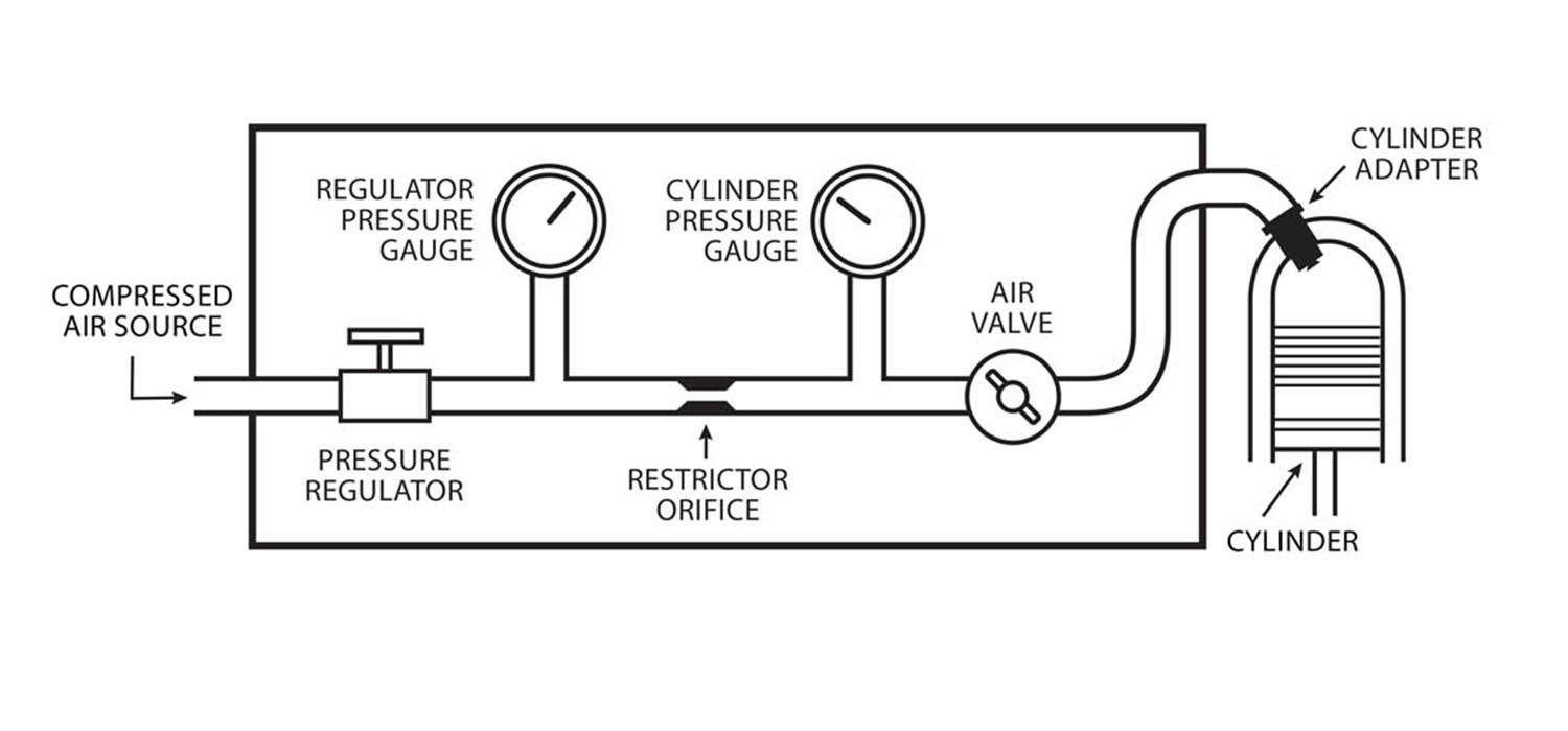
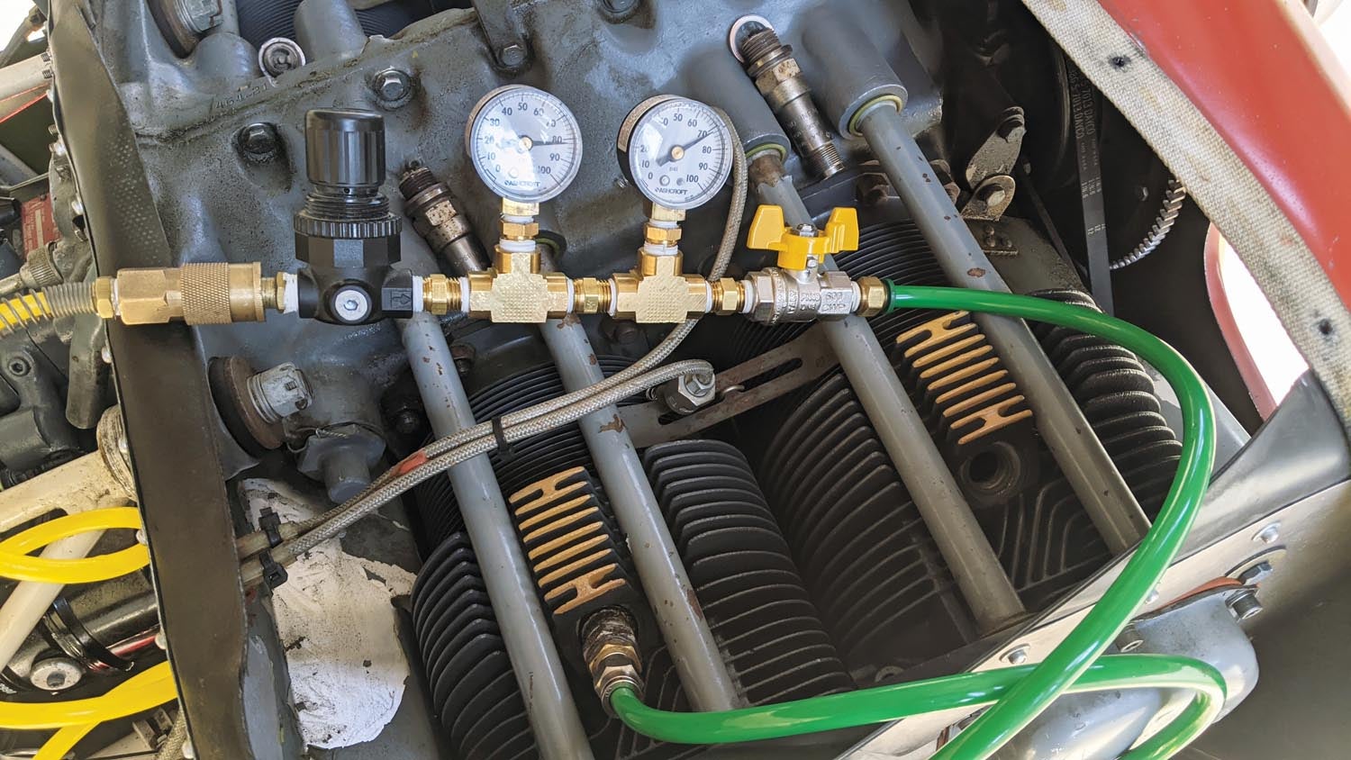
The FAA’s maintenance bible, Advisory Circular AC 43.13, gives a good description of a differential compression tester and how to use it, along with a schematic (see illustration). Basically, it consists of a pressure regulator, two pressure gauges with a restrictor orifice between them, and a connection to the spark plug hole in the cylinder with an air valve to shut the flow off. The AC specifies the size and shape of the restrictor:
1. For an engine cylinder having less than a 5.00-inch bore: 0.040-inch orifice diameter, 0.250 inch long and a 60° approach angle.
2. For an engine cylinder with a 5.00-inch bore and over: 0.060-inch orifice diameter, 0.250 inch long and a 60° approach angle.
Most of us, particularly those who are inclined to save a few dollars building a tester instead of buying, are probably dealing with the smaller engines and so will need the 0.040-inch diameter orifice. If you’re being hauled around the sky by a big round engine, though, you may need the larger size.
When a fluid (liquid or gas) flows through a restriction or orifice, there will be a pressure difference across it, which is the pressure it takes to force the fluid through the orifice. The amount of that pressure difference is a function of the amount of flow passing through the orifice and also of the size and shape of the orifice. If you know the characteristics of the orifice and measure the pressure differential, you can calculate the flow. This principle is used on many flowmeters. The math to calculate the actual flow (in gallons per hour or cubic feet per minute or whatever) is messy and beyond the scope of this article, but in general, as long as the flow through the orifice is subsonic (as it will be above about 35 psi on the downstream gauge), it is proportional to the square root of the pressure drop. Twice the pressure drop means √2 or 1.41 times the flow.
But what is the actual flow (in cubic feet per minute or any other units)? Although it doesn’t matter from a practical standpoint when checking your engine, I was interested in the actual number so I would understand the effects of other parts of the system; knowing the actual flow is important when sizing hoses and fittings. Engineering handbooks provide information on flow versus pressure drop for short (length less than diameter), square-cornered or rounded orifices, but here we’re talking about an orifice length more than six times the diameter—more like a combination of an orifice and a short tube. The cross-sectional area of the orifice is the main factor, but the shape is also important…an orifice with a sharp-corner leading edge will pass only 65% as much flow as an orifice with a rounded entrance. It’s difficult to accurately and cleanly make a truly sharp corner, and small variations can have a large effect on the flow.
Once there is a larger radius or taper, however, the actual corner becomes much less critical. A conical taper is easier to manufacture than a radius, which is probably why compression testers use the 60° approach angle. The advisory circular doesn’t explicitly specify a 60° discharge angle, but most illustrations I’ve seen, including the one in the AC, show the same angle on both sides. The length of the orifice is also a factor; the 1/4-inch specified length is quite large compared to the 0.040-inch diameter, meaning that some of the pressure drop will come from friction against the walls.
Calibration
After some searching, I found Continental Service Bulletin M84-15, which gives a procedure to calibrate the tester. At a differential pressure of 30 psi (80/50) it should flow 120±5 cubic feet per hour or 2±.08 standard cubic feet per minute (SCFM). Given this, I could determine the orifice characteristics and extrapolate the flow at other pressures.
Of course, an engine itself is in effect just a large complex restriction, with the air flowing through multiple small openings (i.e., orifices) formed by the piston rings and valves. What you have, in effect, is two orifices in series: The tester orifice is known and unchanging, so for any pressure drop you will have a certain flow. The engine “orifice” is unknown, but can be calculated if you know the flow coming through the tester orifice (as measured by the pressure drop) and the pressure difference through the engine (the downstream test pressure drop to atmospheric pressure). In the end, by measuring the downstream pressure you’re indirectly measuring the combined size of all the leak paths through the engine; lower downstream pressure means more air is escaping through bigger openings…but lower pressure means a bigger pressure difference across the tester orifice and thus more airflow, but pushing more air through the engine will raise the downstream pressure, which…did I mention the math gets messy?
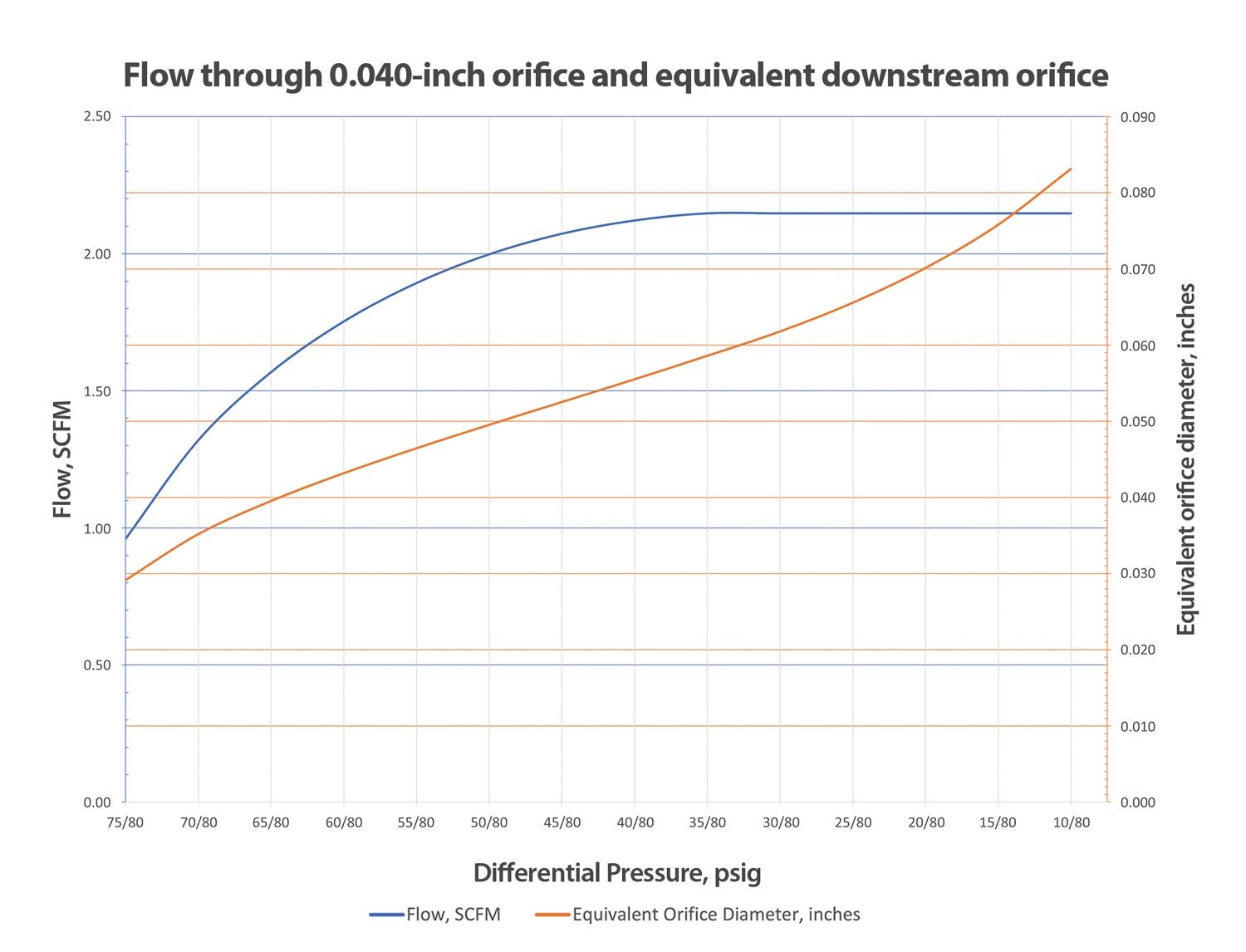
Still, one can do some algebra to calculate a theoretical orifice size equivalent to the sum of all the leak paths through the engine. It’s not terribly meaningful as the tortuous path past, say, a piston and rings isn’t directly comparable to a simple round orifice, but to give an idea of the clearances involved, an engine measuring 75/80 is leaking the same amount of air as would pass through a single 0.029-inch-diameter hole. At 60/80, it’s equivalent to 0.043-inch diameter, and at 40/80, 0.056 inch. As those numbers represent the sum of the leaks past all of the pistons and valves, you can appreciate how small the individual clearances really are…and how much effect even a tiny piece of crud between a valve and its seat can have.
If you see a reading of 80/80, it means no flow at all. Either you’ve found the mythical perfect engine or, more likely, you forgot to open the test valve.
One other interesting thing can be seen from the graph below. The flow through the tester orifice is subsonic down to about 35/80, at which point the pressure difference becomes enough to make the flow supersonic through the orifice. Any further drop on the downstream side doesn’t cause any increase in flow, although that downstream pressure is still indicative of how much restriction there is through the engine. Of course, if your engine is testing in that range you have a problem, and it probably doesn’t matter what the actual number is.
So, while we can calculate the actual flow or equivalent leak area, nobody expects a mechanic to do algebraic calculations every time he does a compression test, and it’s not necessary. By standardizing the orifice dimensions and 80-psi input pressure, we can establish pressure drop limits that correspond to a constant, if undefined, flow rate, and the engine manufacturers have empirically determined what those pressure limits should be.
One other thing that should be mentioned is that Continental specifies the use of a “master orifice” to determine the minimum allowable pressure, instead of a set number like 60/80. This master orifice may be a separate part hooked up to the tester, or it may be included in the tester and switched with a valve. Nowhere could I find anything specifying what size that orifice should be, but many people use the standard tester on their Continentals without worrying about the master orifice…and since I don’t own a Continental engine, I didn’t worry about it either.
The rest of the system just needs to be free-flowing enough to not cause errors. Valves are typically sized by flow coefficient (Cv), which is a measure of how much flow they will allow at a given pressure. Using the 2 SCFM value, I calculated that a Cv of 0.36 would give a 0.50-psi pressure drop. Since I was using 1/4-inch pipe fittings throughout, I used a 1/4-inch ball valve, which has a Cv of 6.5, so it would have a negligible effect. Most ball valves in this size, even if not rated for Cv, will probably be similar. Similarly, I looked at flow in the hose. Two feet of 1/8″ ID (1/4″ OD) hose would give almost 3 psi pressure drop at that flow rate, but a 1/4″ ID (3/8″ OD) hose of the same length would only give a 0.1 psi pressure drop at that flow rate, so that’s what I used.
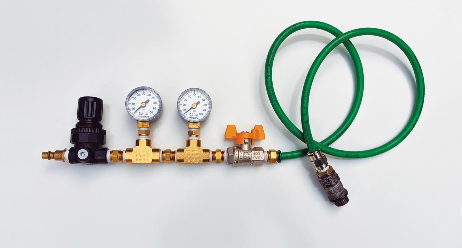
Let’s Build a Tester
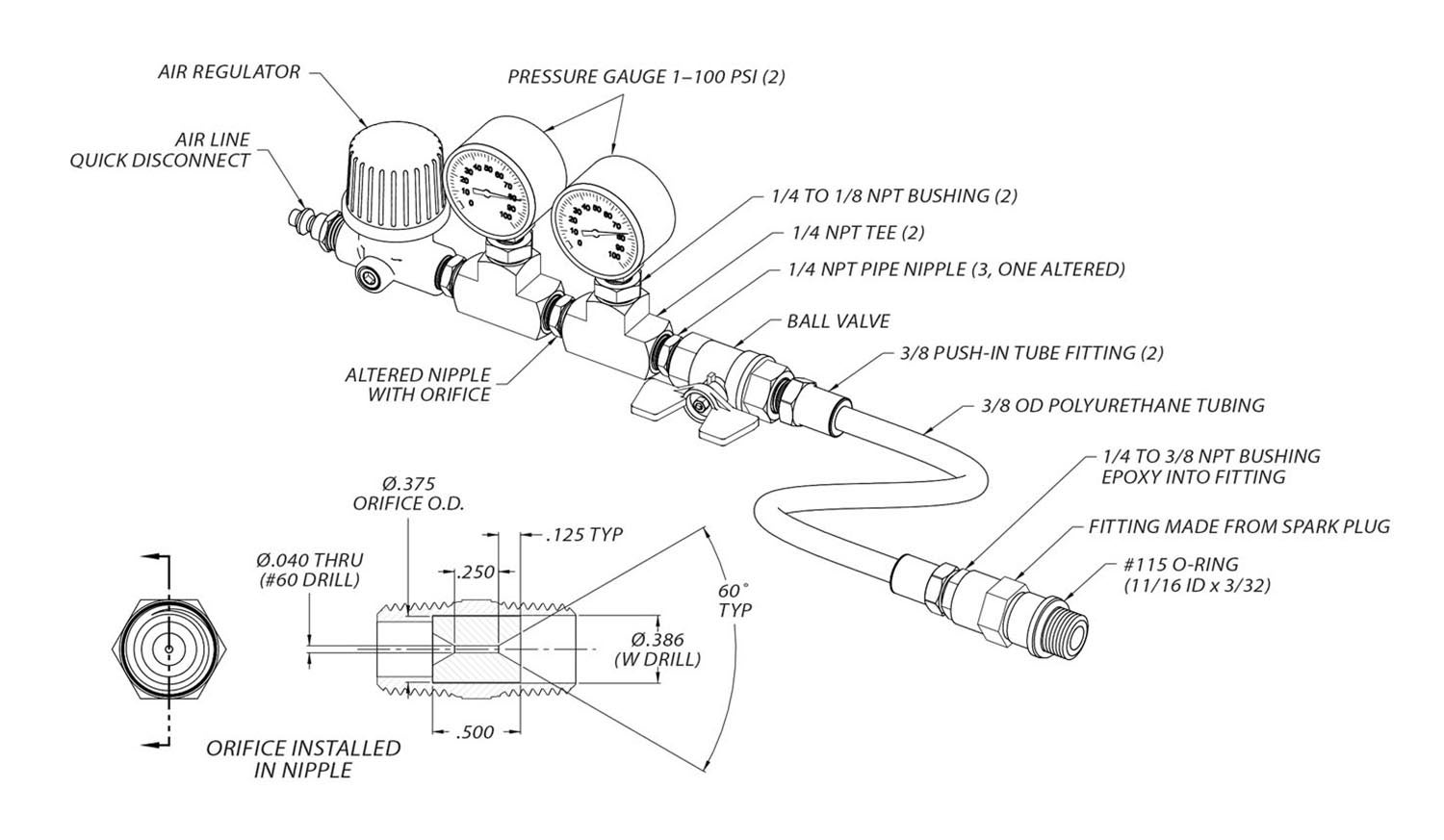
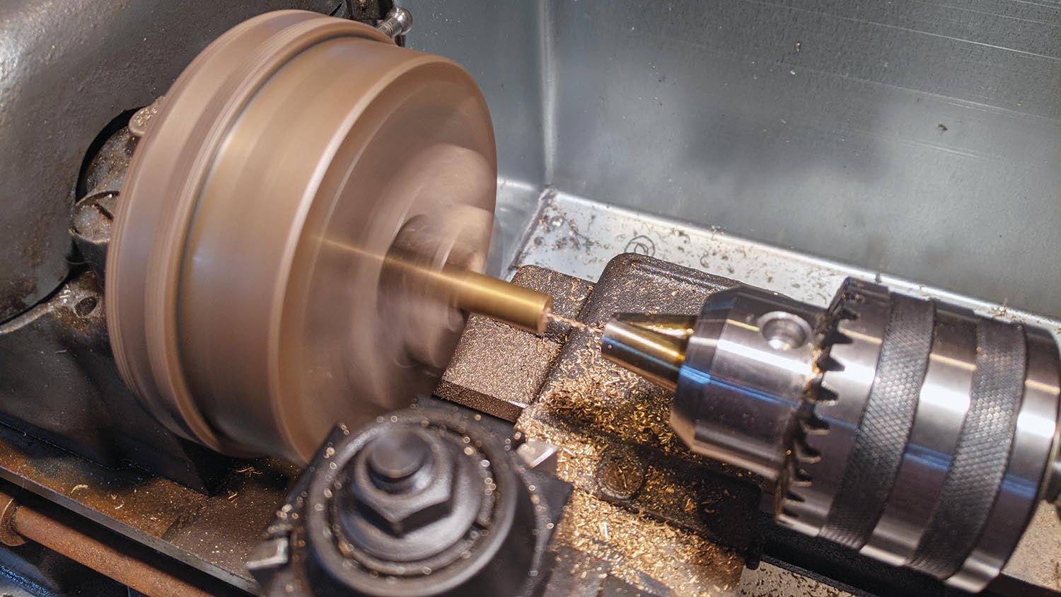
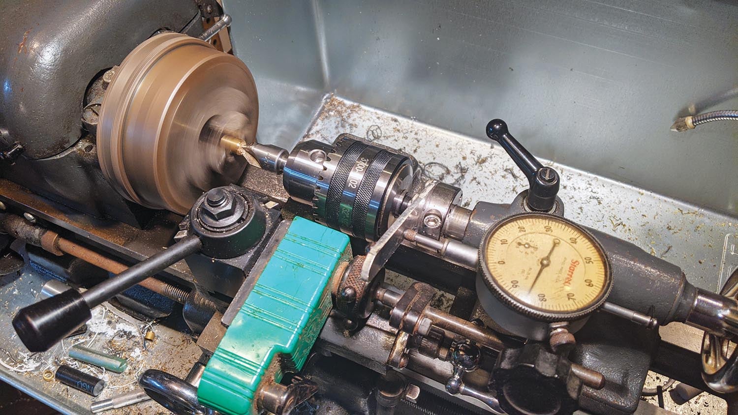
The orifice is made from brass rod, drilled with a #60 (0.040-inch) drill, and countersunk on both ends to form the 60° approach angle. Note that this is not the same as a standard countersink tool for screwheads, which use an 82° or 100° angle. By making the rod 0.50 inch long and countersinking to a depth of 1/8 inch on each end, the 1/4-inch orifice length is obtained. It’s most easily and precisely done on a lathe, but it can be done with a good drill press as long as you’re careful about lining up the back side for the second countersink.
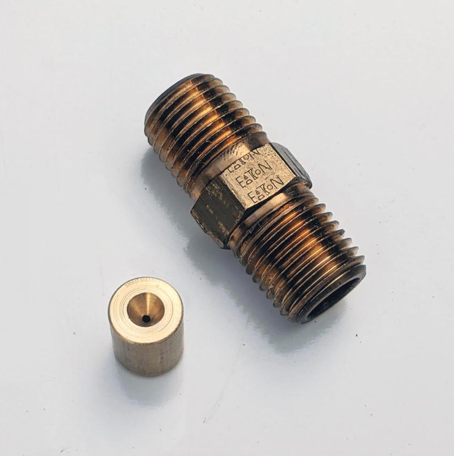
Once made, the orifice is soldered into a pipe nipple bored out to accept it. The hole in the nipple should be 0.005 to 0.020 inch larger than the orifice outside diameter to give space for the solder to wick into. For an orifice made from 3/8-inch rod, a 0.386-inch hole (size W drill) is about right. Or you can leave the nipple unmodified and make the orifice OD fit the existing hole, but boring the nipple provides a step to locate the orifice. Either way, care is needed to ensure that no solder gets into the orifice hole, and be sure to clean out any flux or debris after soldering. Another approach would be to make it a tight or press fit and secure it with some permanent Loctite; in this case the nipple should definitely be bored so the step can support the orifice against the pressure.
After making the orifice and assembling it with the other parts to make the tester, I set it up with a flow meter in the lab and found the actual flow at 50/80 to be 1.98 SCFM, which is well within the 2±.08 specification, so I was good to go. Actually, I made three orifices and tested all three; two were good and the third (which I scrapped) was about 5% higher, though that may have been leakage in the fixture.
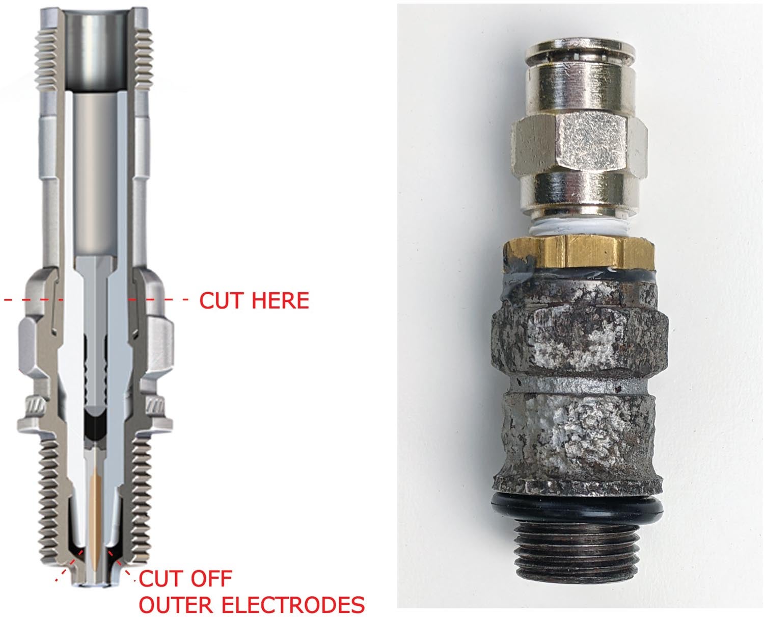
For the engine end, you can buy an inexpensive spark plug adapter with a standard quick disconnect already installed, or you can make one from an old spark plug, which is what I did. First, cut or grind off the outer electrodes. I used a rotary tool with an emery cutoff wheel for that. Cut through the barrel of the spark plug just above the hex until you reach the porcelain insulator; this is where it’s crimped to secure the porcelain (see illustration). I used my lathe for this, but a hand grinder would also work. Finally, tap the center electrode and insulator out from the threaded end. The hole that is left is almost big enough for a 3/8-inch NPT pipe bushing to drop in. The bushing is then glued into the fitting with epoxy. I used JB weld, which contrary to the name isn’t “weld” at all but ordinary epoxy reinforced with steel particles for greater strength and stiffness. Depending on the brand and construction of the spark plug you use, you may have to drill it out a bit for the fitting to go in all the way. If you have a pipe tap, you can also thread the hole, as I did. The existing hole is too big to get much thread engagement so it certainly won’t seal without the epoxy, but it should make it a little stronger. It could also be welded if a steel bushing is used, though whatever plating is used on the spark plug may be an issue.
One departure I made from conventional practice was to use the push-in tube fittings commonly used on industrial machinery, rather than the more familiar ones usually used on portable equipment. These are less robust than the garage air hose quick disconnects, but that’s less important for a tool used occasionally by an aircraft owner than it is for a busy shop. More important was that they’re easier for my arthritic fingers to manage. Standard disconnect fittings could certainly be used instead, and I did use a standard air chuck fitting on the supply side where it connects to the compressor hose. Of course, all pipe joints must be sealed, either with Teflon tape or pipe joint compound.
The remainder of the tester is standard commercial parts. It’s probably best to use two brand-new identical gauges so that any errors will (hopefully) be consistent and cancel each other out. I used Grade B gauges, which have an accuracy of 2%, or 2 psi for a 100-psi gauge, and as far as I could tell this is the grade used in the store-bought testers. Grade A (1% accuracy) gauges are available but cost three times as much, and the ones I found were all liquid-filled to damp vibration (not important here) so they need to stay upright, which is not always convenient. They’re often larger, too, and won’t fit side by side unless you use a longer nipple for the orifice between them.
How To Use It
Using the tester is no different from a commercial one. I find the push-in fitting easier to connect; they also allow the host to be disconnected at either end. Leaving the hose on the adapter and disconnecting it from the tester while holding your thumb over the hose is nice when looking for TDC on the compression stroke. If pressing on the release ring is difficult, a short length of 7/16-inch ID rigid tube or pipe slipped over the tubing (not shown on the drawing) can make it easier.
There you have it. Realistically, if you have to buy all new parts to build a tester you probably won’t save all that much over buying a tester, but that could be said of building airplanes in general. But if, like me, you have lots of extra parts lying around, it pays for some avgas, anyway. Oh, and my engine? The two low cylinders got worse and another went down, as low as 30/80. Borescoping didn’t show anything, but with the local A&P’s assistance we ground the valves in place in the engine and got the compressions back up over 70/80. I love it when it’s a simple fix.


Years ago someone started calling car wheels “rims”. A bucket has a rim.. Similarly, someone in aviation started calling a leak down tester “compression tester”. Since then everyone in aviation makes the same the same mistake. Your device is a leak down tester. The link below talks about the two.
https://www.pegasusautoracing.com/document.asp?DocID=TECH00137
True, it’s properly called a “differential compression tester”.
Jeez for $100 bucks your gonna waste your time building this ? By the time you factor in labor, you are probably up to $200 for a Rube Goldstein product. And what testing facility is gonna test calibration on it every year? come on !
calibration? this is experimental aviation. Do you honestly think average people are calibrating most of their equipment like torque wrenches on a regular basis?
As I said in the article, it won’t save much, unless you have parts laying around, as I did. But also as I said, that’s true of building airplanes, too. It’s all about the learning and enjoyment of the process.
I enjoyed your article and learned a few things in the process and I am a 78 yr old Electronics Engineer with A&P with I/A pilot multi and instrument and owned may planes over the years. This article was so interesting. Thank You!! My current plane is a Questair Venture
Hi Dana,….Thx so much for putting all this up .This is a Huge amount of detail, hard to find info….I believe the TCM Continental M84-15 “Master Office Tool” makes design spec reference to the same FAA AC 43.13-1B 0.040″ id orfice….. Wouldn’t that “Test leak Tool” calibration device leak at 40/80 ?? …..
If you Measure the Exact same 0.040″ id constructed Orfice with your Gauge, What should the expected gauge Readings be ?
From the graph, it looks like it’d be around 64/80.
Comments are closed.