 A baffle duct is a simple device that channels cooling air from behind one of the cylinders down to an oil cooler, but if any of the commercially available models don’t fit your particular firewall-forward layout, it’s pretty easy to make one out of fiberglass.
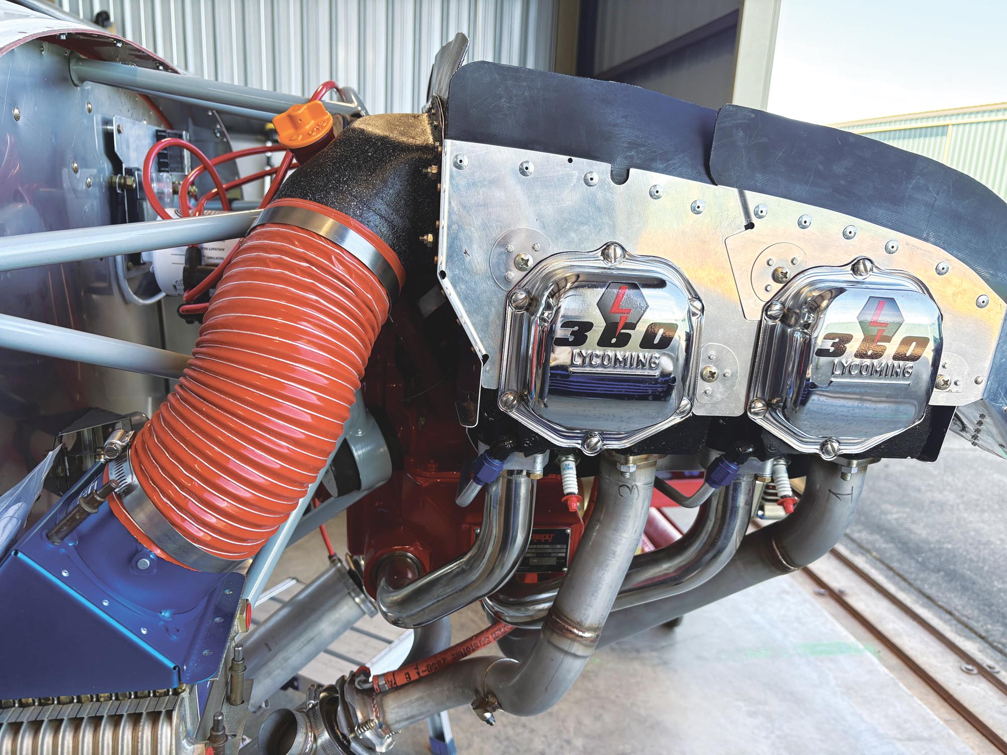
My 13-row oil cooler is fitted with a 4-inch SCAT tubing flange, but there isn’t enough room on the baffle behind the Number 3 cylinder to place a 4-inch-diameter round flange to feed it. Even a rectangle wouldn’t fit very well there. To get around that limitation, I came up with a shape that fits the area better—sort of a rectangle with one sloping side that follows the slope of the baffle with the same area of a 4-inch circle.

So, how do you make a mold for such a duct that starts off as a notched rectangle and ends up as a 4-inch circle? Well, we know the shapes we need at the starting point and at the ending point. The trick is to fix those two shapes in space relative to each other.
Shape
Start by making a plate out of plywood about ½-inch thick in the exact shape of the baffle opening. We’ll call this plate “A.” That will determine the shape of the duct at the start. Next make a circle of the same material to match the SCAT tubing you plan to use—in the case of 4-inch SCAT, make the diameter 3.85 inches. This is to account for the thickness of the fiberglass layup. This will be plate “B.” We’ll use ⅜-inch 3003-0 soft aluminum tubing to keep the two plates apart, so drill a 0.37-inch hole in the center of each plate.

Attach plate A to the aft side of the baffle with two Clecos, exactly where the opening will be, and mark the baffle for the location of the center hole. Now remove plate A from the baffle and drill the center hole to about ¾ inch. The hole is there just as a temporary pass-through for excess tubing, so the exact size is not important. A step drill works well here.
Cut a length of tubing about 4 inches longer than the finished duct and dress the edges. If you use a tubing cutter, the edges will be sufficiently chamfered.
Push one end of the aluminum tube about an inch through the center hole in plate A. The tubing has to fit tightly in the center hole as we rely on this to hold our parts firmly in place.

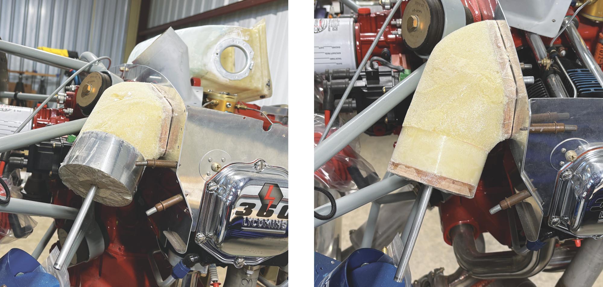
The aluminum tubing will now serve as the centerline of your new duct, so bend it approximately into shape from the baffle opening down toward the oil cooler. When you get it close, slide on plate B and push it to the spot where you want the duct to end. Attach plate A to the baffle with Clecos again and fine-tune the shape. When done, you will have the two points in space that define the duct shape. Drive a short screw between the plate and the aluminum tube on the aft side. This screw is there to prevent the tubing from rotating relative to the plate as you manipulate it.
For the SCAT tubing to fit tightly onto the duct, the area where it slides over the duct should be uniform in size and shape. To accomplish that, I used aluminum flashing, but card stock with tape or very thin plastic will work too. Cut a 2×13-inch piece of flashing and wrap it around the perimeter of plate B and tape it in place with packing tape. Make sure it forms a cylinder and not a cone.
Place everything back on the baffle, Cleco in place, and confirm the shape and dimensions are what you need for a smooth transition from the engine baffle to SCAT tubing toward the oil cooler.

Foam
The next step is to create a vessel that will contain expanding foam. The goal is to make it slightly larger than the finished duct.
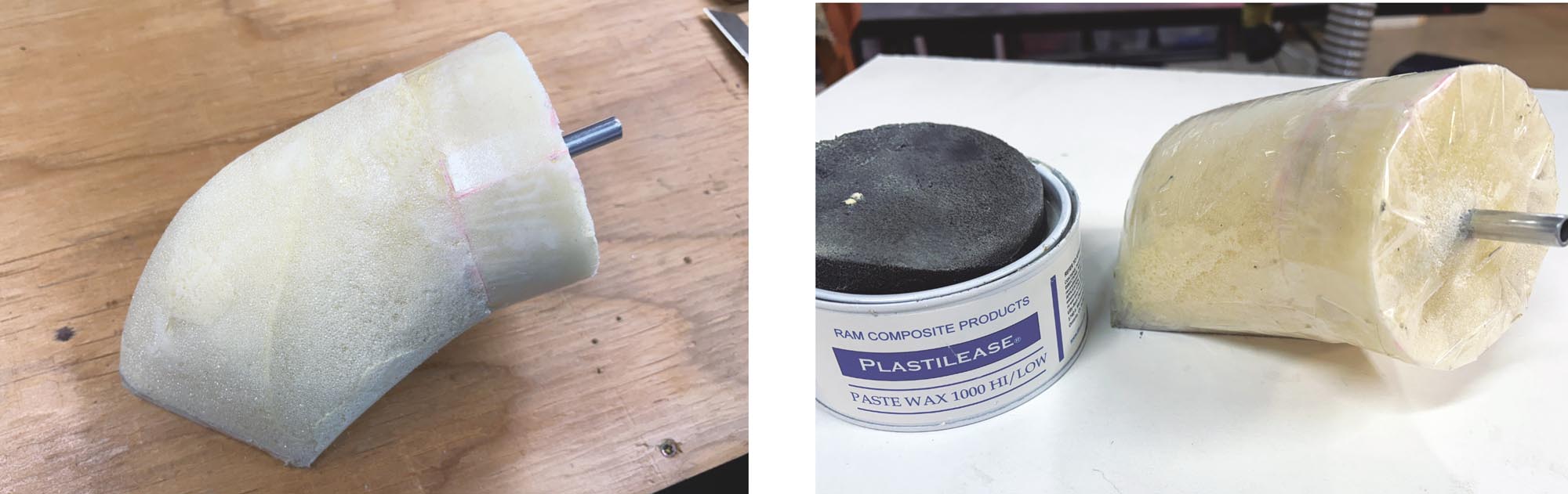
Tape over the insides of the two plywood plates and lightly wax those surfaces, and also wax the inside of the cylinder.
Start creating the vessel by stretching packing tape from the sides of plate A to the sides of plate B. The exact shape is not important, but it is important to make it larger than the final duct shape. Leave about a 2-inch opening through which you can pour foam. You could place everything in a cardboard box and fill that with expanding foam instead of using tape, but that just wastes foam and makes a bigger mess.
X-30 Expanding Foam is a two-part mixture that expands to 30 times its original volume and cures to a rigid 2-pound density foam that is easy to carve and sand to shape. Aircraft Spruce and retailers like TAP Plastics carry it. Do not use the expanding insulation foam that’s sold in hardware stores. Measure equal parts of the liquids into two separate cups, then mix them together according to the instructions. Remember that you will get about 30 times more than what you mix, so eyeball it accordingly. It is, however, better to mix more than less. Even though you can add more foam 10 minutes after the first pour, the crust that forms between pours sands differently than the middle, so try to avoid that.
The foam will cure quickly in a warm shop. When it does, remove the packing tape, but leave the flashing in place. Carve and sand the duct to a gentle curved shape flush with the sides of plate A and the flashing around plate B. Gently remove the flashing and plate B and confirm that the diameter on the round end is correct for the SCAT tube. Now is the time to make adjustments by either adding some duct tape or by sanding it smaller. Remember to account for the thickness of the fiberglass layup.
Glass
Now that we have our shape finalized, we’ll glass over the mold. X-30 foam is impervious to solvents, so to make separation from the finished glass duct easier, wrap the foam mold with packing tape. Brown tape works best because you can see it. I only had clear tape on hand so that’s what I used. Wide tape won’t easily conform to the compound curves of the mold, so use smaller pieces and even split some pieces lengthwise to obtain a wrinkle-free wrap.

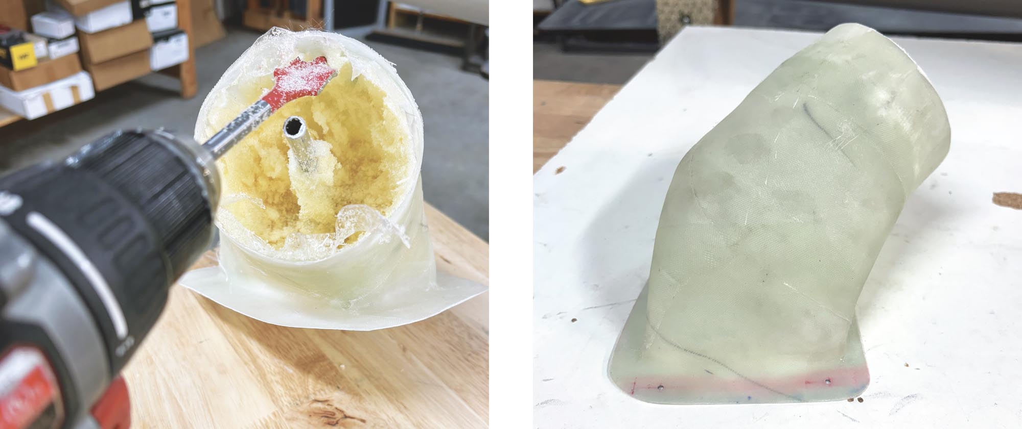
Cut off the excess tube protruding from plate A.
To make the flange that butts up to the engine baffling, the duct will be glassed with plate A down on the work surface. A flat sheet of melamine makes a great surface for fiberglass work, but any flat surface will do. Attach the mold to the work surface with thin double-sided carpet tape, then wax about 4 inches all around it and wax the mold itself.
Mix up a small batch of resin and make a thick flox or chopped glass mix and create a fillet all around plate A to help the fiberglass transition smoothly. A finger-wide diameter is fine.
Because of the compound shape, you’ll have to use several smaller pieces of cloth rather than one big one. Lay up three plies of 9-ounce cloth and push the cloth tightly into corners where it turns into the flange. Finally, I like to use peel-ply because it allows me to pull everything tight and smooth without distorting the glass weave. It also soaks up excess resin making the layup lighter.

Once the layup has cured, cut the flange 1½ inches all the way around and smooth out any imperfections. Finish with paint if you like, and attach to the engine baffling with four #8 screws.


Nice job Omar. I wish you wrote this last summer!!
Excellent write up!
Brilliant!
I did the lower plenum similarly, using a pool skimmer sock instead of flashing to make the transition. I crumbled up styrofoam chunks from a broken kickboard into little balls, stuffed them into another skimmer sock to fine-tune the shape, then painted resin on the sock. After the resin cured I did the layups right on top of that.
Comments are closed.