 The SR-1 race plane is a one-off design and therefore requires a custom engine mount. The engine, an EP912STi from Edge Performance (see my article “On the Edge” in the February 2023 issue of KITPLANES), came with the stock Rotax engine mount. This is a stubby ring mount that serves as an interface for each manufacturer’s unique engine mount, so most aircraft with a Rotax engine actually have two engine mounts: the Rotax ring mount and the manufacturer’s mount that spans the firewall to the ring mount. Vibration isolators typically (but not always) are placed between the ring mount and manufacturer mount. The design of the Rotax does not allow for vibration isolators at the rear of the engine itself, as would be typical with a Lycoming or Continental.
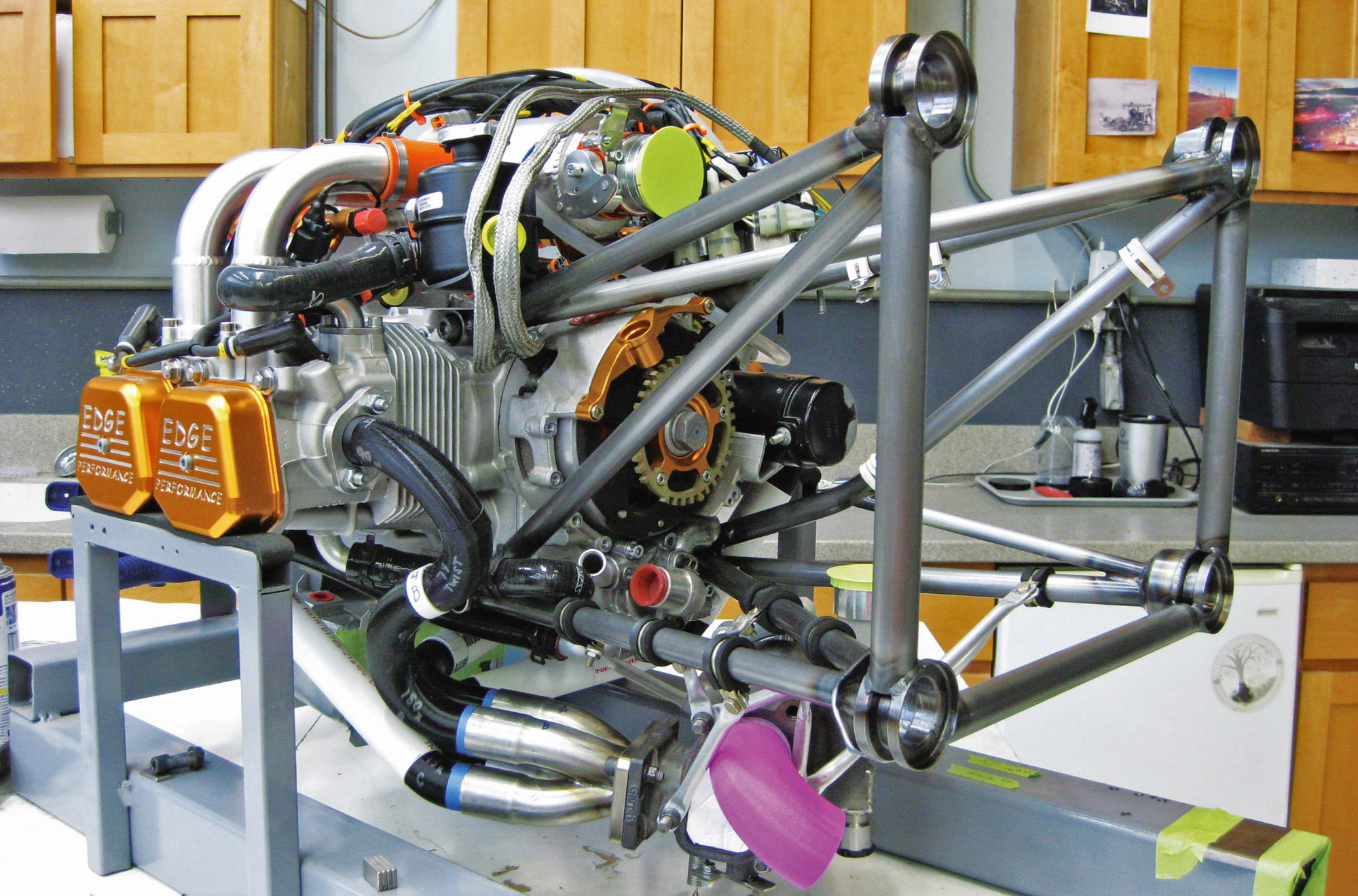
This double-mount approach makes sense from a manufacturing and kit integration point of view, but it presents both weight and packaging disadvantages for the SR-1. Because I would need to fabricate a custom mount regardless, it made sense to design the mount as a single weldment that optimized weight and accommodated the relatively tight firewall packaging of the SR-1 (if you open this magazine on a coffee table, that’s more area than the SR-1 has for all its firewall-forward components).
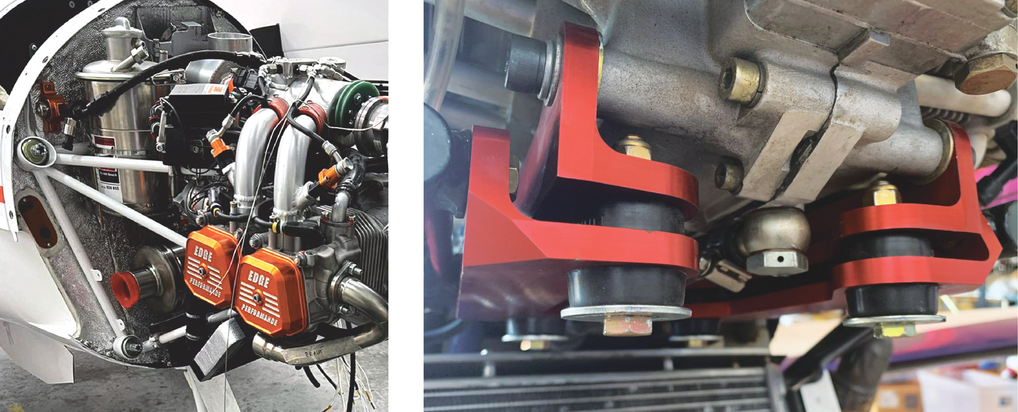
One consequence of the single-mount approach was the need to determine how to incorporate the vibration isolators. For example, the European Shark UL (www.shark.aero) locates the isolators at the firewall. Sonex offers another solution: a bed mount that interfaces to the engine via isolators and attach bars. That said, packaging considerations precluded the use of a bed mount. In addition, my initial impression was that a bed mount did not appear to possess a weight advantage and might not be as capable at damping vibration compared to a rear mount. Those are my suspicions only—I did not have the time or budget to explore bed mounts as a solution, and for other aircraft that approach might be a solution.
Because the Shark UL is a similar airframe (i.e., fast plastic) and engine, I felt comfortable following a similar approach and placing the isolators at the firewall. As far as I am aware Shark.Aero has had no issues with this approach, and Thomas Hauklien, CEO of Edge Performance, told me he had had no engine mount or vibration issues with his own Shark, which also uses the 912STi.
Design
The firewall mount points were fixed during the initial fuselage design. Carbon fiber longerons terminate at the rear side of the firewall in a composite bracket with a metal hardpoint, similar to those seen in Lancair designs. The distance from firewall to engine was dictated by packaging and CG considerations. With four nodes for the engine mount fixed at both the firewall and engine, respectively, the primary fore-aft tubes were located, followed by secondary tubes that resist torsion forces. Tube centerlines intersect at their particular node in order to approximate a pin-jointed truss system and thus minimize bending forces on the bolts and tubes.
Finally, a set of tubes in the shape of a U connects the outer edge of the vibration cups to resist any bending or twisting on the cups induced by the combination of tension, compression, and torsion loads from the engine to the mount. This is nearly identical to the Shark design.
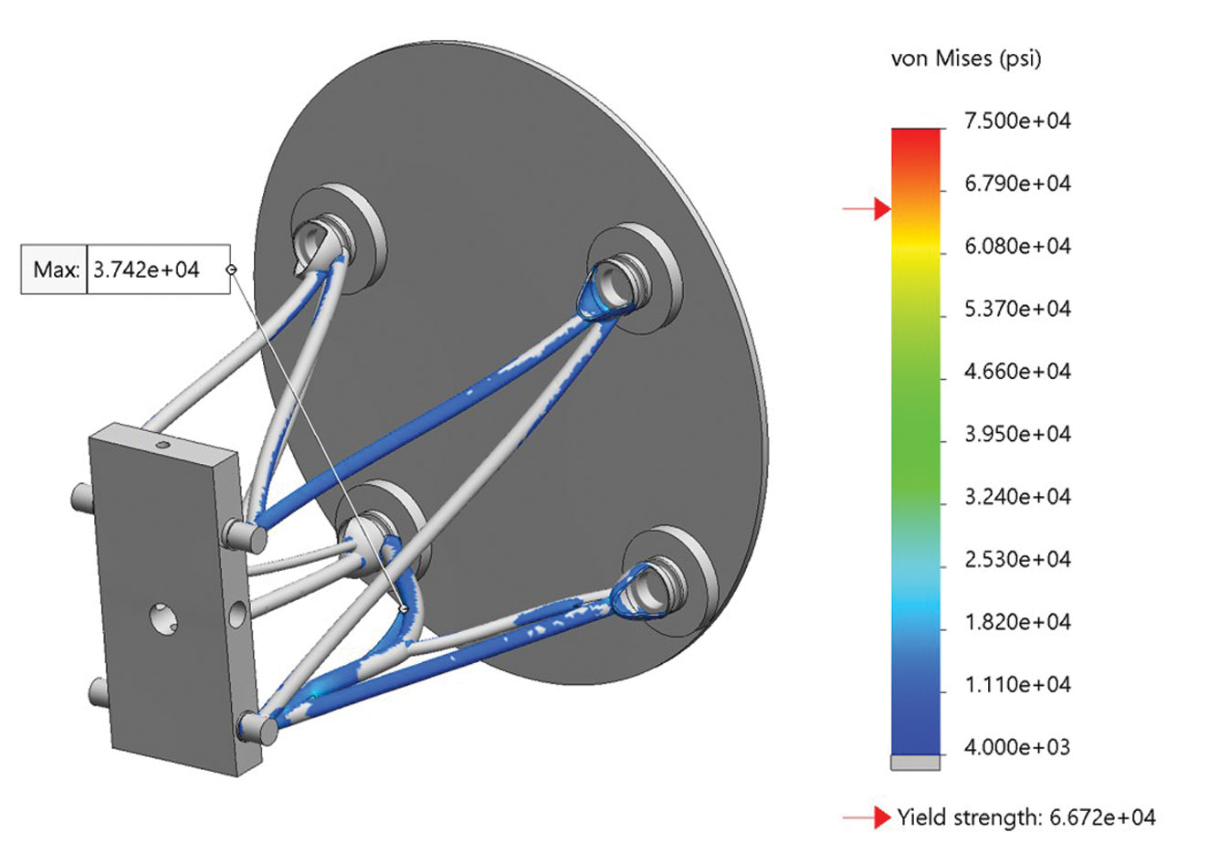
The mount was modeled as a weldment in SolidWorks and analyzed for stress hotspots (SolidWorks was offered through EAA for some years, discontinued in 2022, and is now available again in a cloud-based version). Loads used in the analysis were in line with those prescribed in FAR 23.361/363. Hotspots in the FEA model were identified and mitigated through changing mount geometry or increasing tube diameter and/or wall thickness. It should be noted that hotspot stress limits were dictated not by the nominal yield stress of the mount material (4130 chromoly) but by a knockdown based on fatigue limits.
Welds were modeled as fillets and as such geometrically simulate the shape of the weld but not inherent stresses due to welding, reductions in stress due to yielding, differing strength and modulus of filler vs. parent material, and other relevant factors. That said, analysis gives a rough indication of areas of concern, and the final design result was in close alignment with existing engine mounts for similar applications and power levels. The mount will be static stress-tested to the above FAR loads before acceptance for flight.
Fabrication
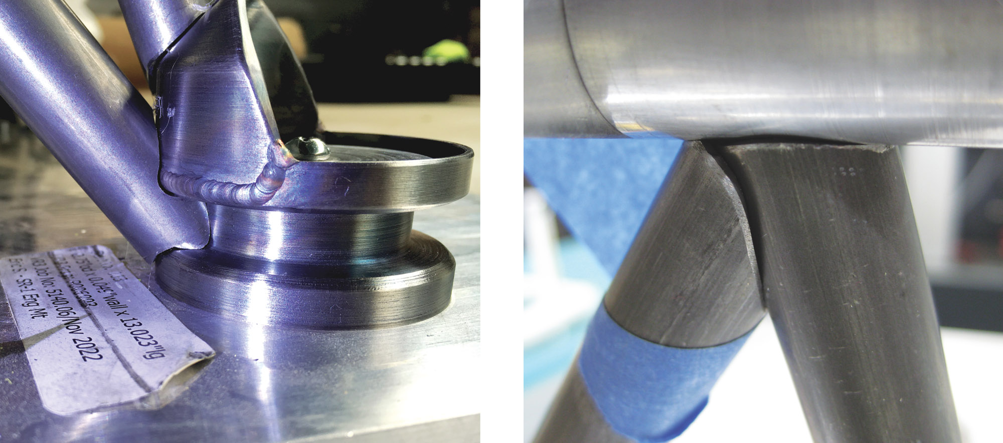
The mount consists of three distinct part types: “spools,” tubes, and “cups.” The spools look like thread spools (or large bushings) and capture the bolts that thread into the engine case (horizontally, from the side). The cups hold the rubber vibration isolators; bolts anchor the isolators to the firewall. Tubes run between the spools and cups. All parts are 4130N chromoly.
The spools are identical to the spools on the stock ring mount and were turned on a manual lathe. The cups were CNC’d by SR-1 sponsor Richard Squires, owner of Langaire Aircraft Parts. (Squires machines these cups for the Vans RV-12 engine mount.) The cups were then slightly modified with additional lathe and mill work before being welded with a “hood” that provides a location to weld several of the mount tubes. The hood was a separately CNC’d piece.

SolidWorks will generate a cut list and drawings from your weldment model. These were sent to VR3 in Canada, a well-known tube CNC cutting shop. Working with VR3 was a great experience—VR3 supplies many university student engineering teams with tubing for the Formula and Baja SAE contests. Because some of the student teams have limited experience CAD modeling something like a roll cage, VR3 provides a very detailed and educational guide to creating weldment models and generating cut lists, complete with step-by-step checklists on their website. This ensures that customers get perfect tube sets, and VR3 doesn’t waste time fixing incorrectly modeled weldments.

And I mean perfect. My tube sets fit so precisely that you couldn’t slip a piece of paper through most of the joints. This made the initial fit check before final welding extremely easy and made the welder’s job easier too. The tubes literally fit together like a jigsaw puzzle, with zero wobble or slop. This was great because there are a couple of places where the mount has very tight clearances to other parts of the engine, and having a tube offset by more than 1/16 inch would have been problematic. As it was, the finished engine mount mirrored the computer model to within a few hundredths of an inch and all clearances were maintained.
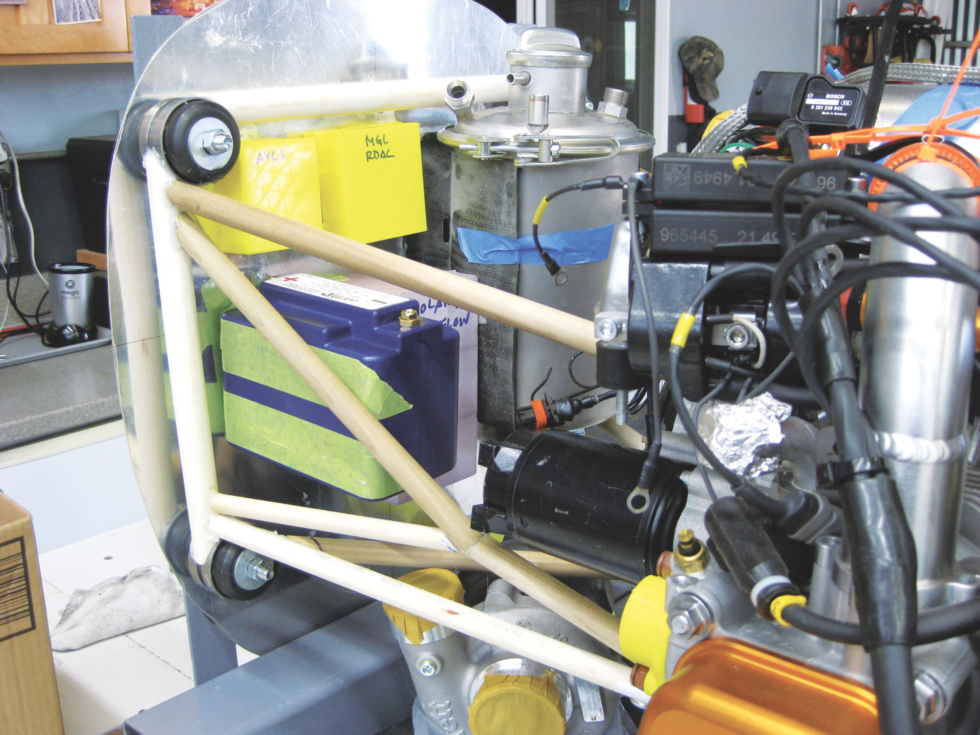
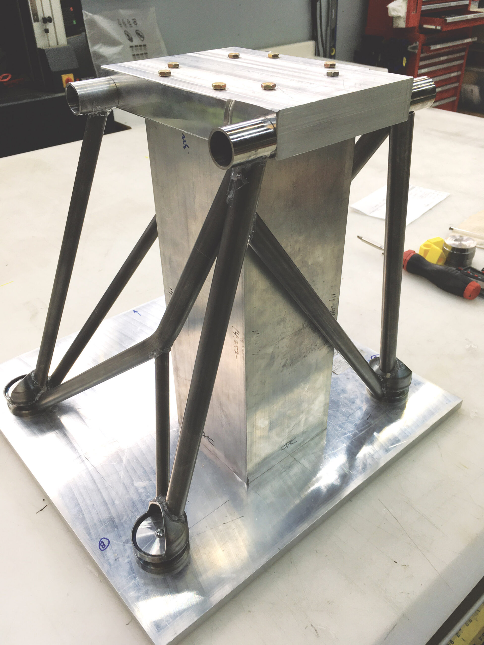
Key to ensuring that the actual mount matched the computer model was a weld jig, also modeled in SolidWorks. The base of the jig was a half-inch-thick sheet of 6061 that represented the firewall. The vibration isolation cups were located over their respective locations and fixed in place with a centering plug. Likewise, the spools were bolted to the four corners of another aluminum plate machined to represent the engine attach points. The accuracy of this plate was confirmed by simply checking that the stock Rotax ring mount bolted to the plate. These two plates were then bolted to a 6×6-inch aluminum square tube that represented the separation between engine and firewall. Finally, the V3R tubes were fitted between the cups and spools. A perfect fit between all parts confirmed that the mount parts, jig, and CAD model were all in agreement and the mount was ready for welding.
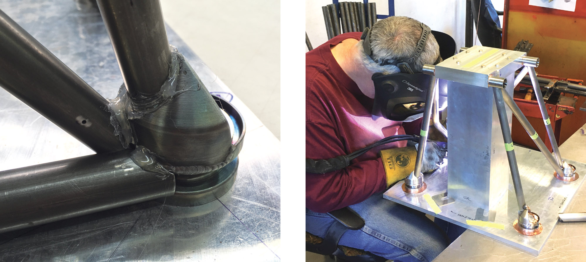
Russ McCutcheon, who provided various weldments for all models of Van’s Aircraft before retiring, welded the mount. I was familiar with McCutcheon through his postings on Van’s VAF as a fellow RV-4 builder. Since Russ is welding 4130 tubing practically every day, I felt confident that he would successfully take the mount through the final step. To be honest, Russ’s beautiful welds are consistently the number-one compliment generator when folks see the FWF!
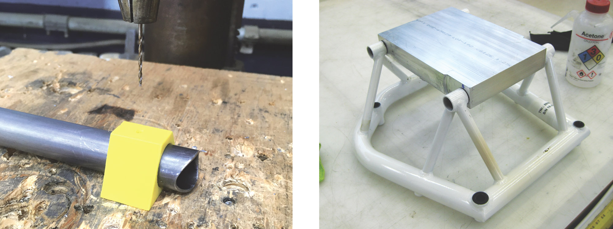
Prior to bringing the mount and jig to McCutcheon, all parts were prepped by cleaning with acetone, followed by abrading with a Scotch-Brite pad any areas to be welded. Although chromoly is rust-resistant, it certainly isn’t stainless, so parts were wiped with WD-40 as a preservative until the time to weld arrived. Likewise, once the mount was finished, WD-40 was reapplied. The mount still needs to have several support tabs welded to it, but once all welding is complete the WD-40 will be again cleaned off and a coat of epoxy primer and paint applied.
One final prep note: All tubes that are closed up by the weld process should have a small hole drilled in them to allow air inside the tube to vent. Failure to do this will cause the hot air inside the tube to blow out the weld as the welder tries to close up the weld. A small rosette weld can be performed afterward to seal the hole if desired (a rosette doesn’t generate enough heat to cause a blowout). Additionally, some also inject linseed oil or other corrosion inhibitors to coat the tubes internally (see AC 43.13 6-42). Chapter 4, Section 5 of AC 43.13 provides guidelines for aircraft welding and is recommended reading even if you don’t plan to do the welding yourself.
The Experience
Fabricating a CNC’d custom engine mount was a fun and educational experience, and I was quite happy with the final result. It was really cool to model the mount in SolidWorks, and subsequently fabricate the jig and individual mount parts, and then have everything piece together precisely with no additional work required. The close fit also made the job of the welder easier, and the mount fits perfectly. Weight is slightly less than had I used the double-mount approach, and packaging is significantly better. Price-wise, the mount was not terribly expensive, but it did entail a lot of work on my end to engineer, so there was certainly a cost in terms of time. So if you like learning, try making an engine mount. If you prefer to fly, then maybe go with off-the-shelf!


