For the past few months, we have been concentrating on the primary cooling airflow and flow path for the air that cools the cylinders of the engine and carries away most of the waste heat generated by combustion of the fuel. This primary cooling system is a critical part of the engine installation, but the primary cooling flow is not the only cooling flow or internal airflow needed by the airplane.
There are components and systems aboard, both within the engine compartment and the cabin, that require their own cooling flow to keep them within their operating temperature range. Cabin ventilation is also necessary and will require an airflow system that is entirely separate from the engine compartment cooling and ventilation airflow.
Secondary Cooling Within the Engine Installation
As we have already seen, the majority of the waste heat generated by the engine is absorbed and carried overboard by the primary cooling flow air that flows over the cooling fins on the cylinders of the engine. The exhaust system is also cooled somewhat by the primary cooling flow, rejecting heat into the air in the lower plenum before it flows overboard through the outlet.
There are two other cooling tasks that need to be addressed within the engine compartment.
First: The oil that circulates through the engine to lubricate it absorbs heat from the engine itself. On most installations the oil cannot reject enough heat through the walls of the sump to stay at an acceptable temperature, so a separate heat exchanger is needed to cool the oil.
Second: There are multiple engine accessories installed along with the engine that can both generate waste heat and absorb heat radiated by the engine. All of these have temperature limits and may require supplemental cooling if simple convection into the primary cooling flow is not sufficient.
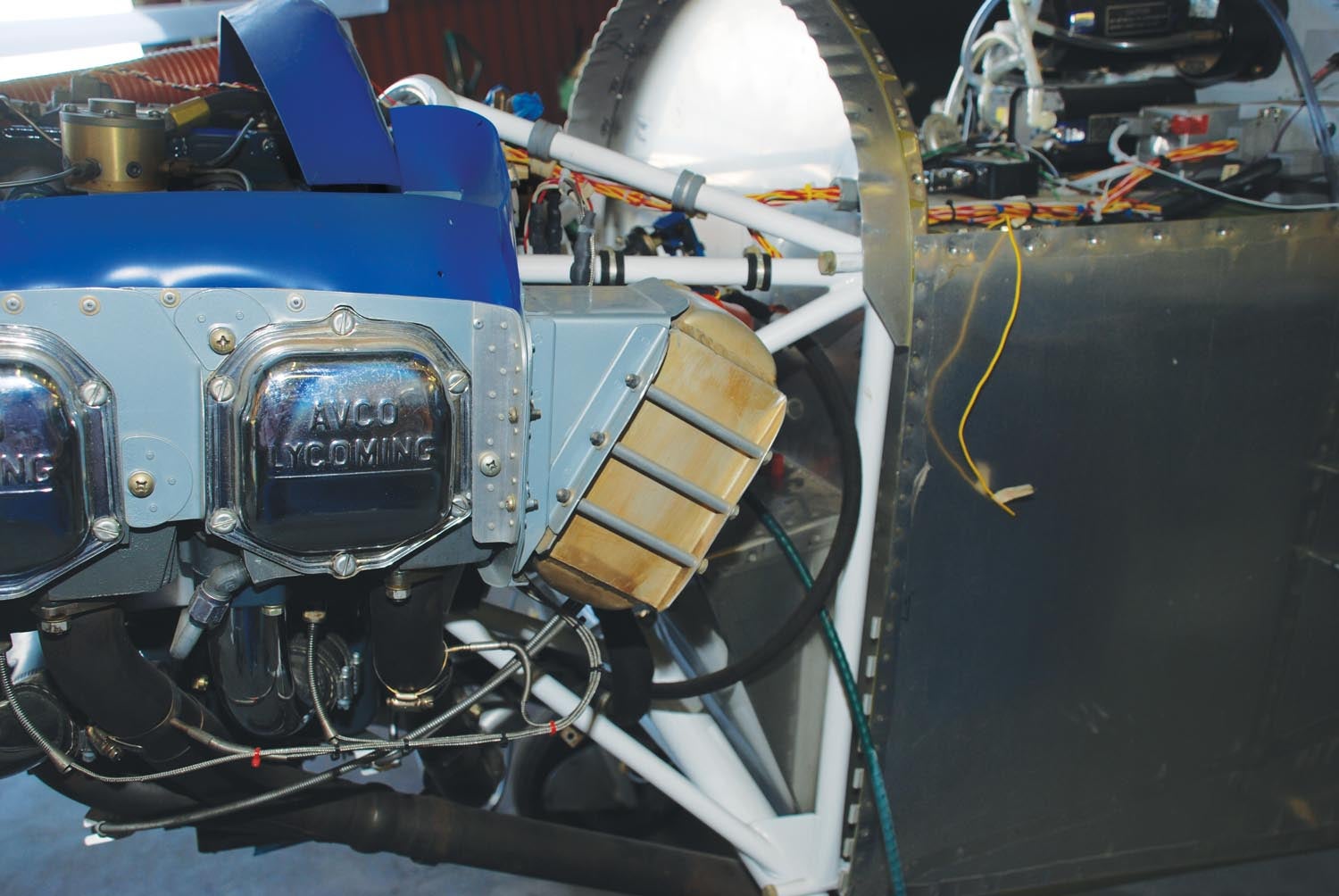
Oil Coolers
Many airplane engines have oil coolers to control oil temperature and carry away additional waste heat from the engine. An oil cooler is a heat exchanger much like a radiator. Oil flows out of the sump, through the oil cooler and back into the sump. Within the cooler oil flows through passages in a set of cooling fins. Cooling air flows between the fins and absorbs heat from the oil.
An oil cooler requires a flow system much like that for an engine cylinder. There must be a pressure differential between the entry side of the cooling air path through the fins and the exit side. The cooler should be sealed around its sides so all of the available air is directed through the fins.
Two Common Installations
There are two common approaches to oil cooler installations. The first is to incorporate the oil cooler within the primary cooling air system. The second is to provide the cooler with its own separate flow path.
In the first approach, the cooler is mounted to one of the primary baffles that form the upper plenum. There is a hole in the baffle that matches the face of the oil cooler. This hole allows high-pressure air from the upper plenum to flow through the cooler into the lower plenum.
In this type of installation, the oil cooler acts aerodynamically like an additional engine cylinder. The primary advantage of this installation is that it is relatively simple and light. There are no extra parts required beyond the cooler and its plumbing.
The major disadvantage of this simple installation is that it uses air from the upper plenum. The oil cooler acts like a hole that bleeds off pressure from the upper plenum, reducing the air available to cool the cylinders. This increases the total amount of cooling flow going through the primary system and can make it difficult to balance the cooling flows between the oil cooler and the cylinders. Any change to one affects the others, so it’s common to increase the size of the primary inlets to a bit more than the minimum required so the system is tolerant of minor imbalances between the flow through the cylinders and the oil cooler. While this is a robust solution from a cooling point of view, it does come with a drag penalty.
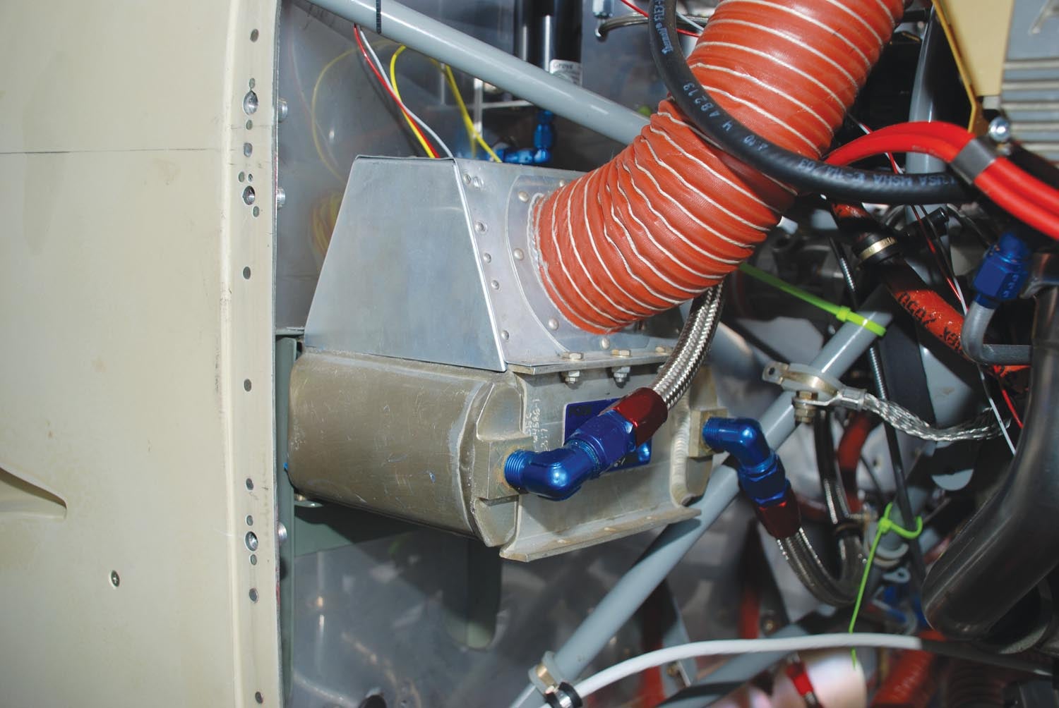
Dedicated Oil Cooler Flow Path
A second approach is for the oil cooler to have its own separate airflow path. A dedicated inlet feeds cooling air into a duct leading to the oil cooler. After the air flows through the fins of the oil cooler, it flows downstream to its own independent outlet.
The big advantage of this approach is that it does not affect the cooling of the cylinders and allows more freedom to optimize the airflow through the oil cooler. It’s also compatible with a variable-geometry outlet for the oil cooling flow, which allows the pilot or engine control system to control the oil temperature directly and minimize the drag of the flow through the oil cooler.
The downside to this approach is that it is more complex and slightly heavier than the simple installation inside the engine compartment. It requires an additional inlet, ducting and outlet, all of which have some weight and occupy volume that must be accommodated within the cowling.
Accessory Cooling
In addition to the engine itself, there are other components within the engine compartment that are vital to the proper functioning of the engine and the airplane’s systems. Among these are the magnetos, alternator, electronic ignition components and voltage regulators. All of them need to be kept within an operating temperature range to function properly.
Because these items are typically installed inside the cowling, on or near the engine itself, they absorb some waste heat from the engine. Some also generate their own waste heat.
Simple convection to the air in the plenums is often insufficient to cool the accessories, so it is generally necessary to provide some cooling airflow over them. They do not get as hot as the engine itself or the oil, so a relatively simple system that blows some cool air over the accessories will suffice.
This is typically accomplished using “blast tubes.” A blast tube picks up high-pressure air from the upper plenum through a hole in a baffle or a forward-facing inlet and carries it to the components (in the lower plenum) that need cooling. The end of the blast tube is aimed at the components to direct a constant flow of cooling air over them.
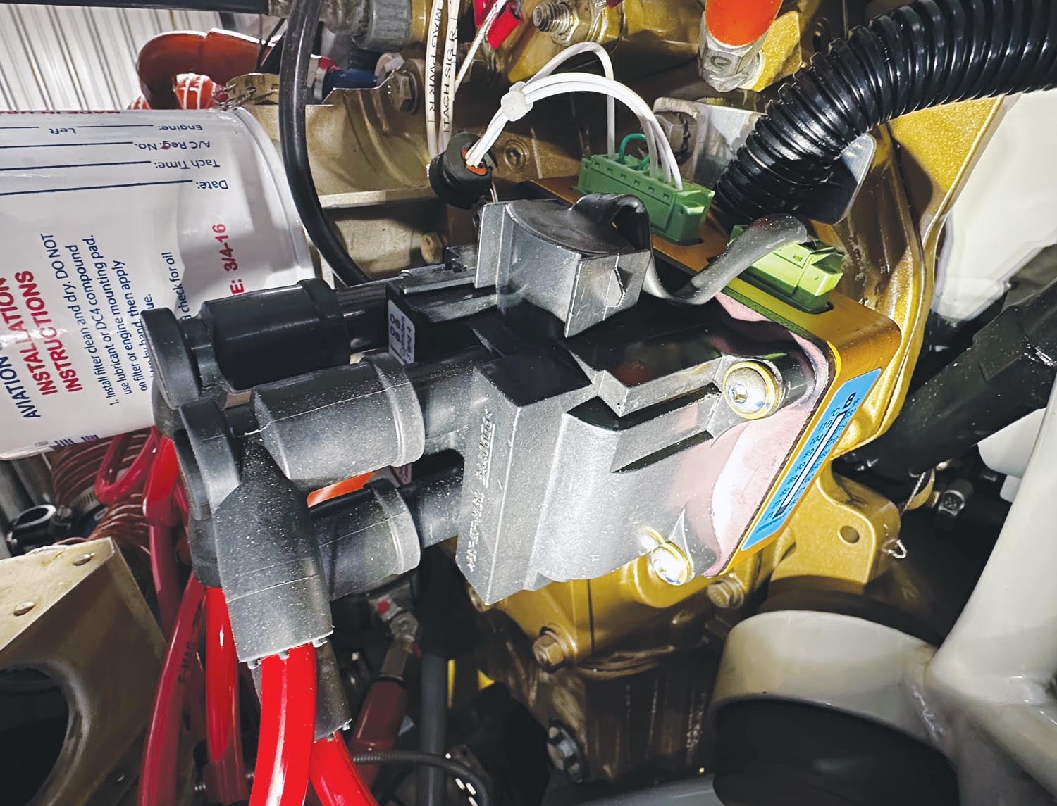
Blast tubes work well and are a relatively simple and straightforward way to cool engine accessories. They do take some air from the upper plenum if they are drawing air through holes in the baffles, so they increase the amount of total cooling airflow. For best efficiency the blast tubes should be carefully sized so that they only draw the air actually needed to cool the accessories and don’t waste cooling air unnecessarily.
Next month we will turn our attention to areas other than the engine compartment that require cooling or ventilation airflow.
Photos: Dave Prizio & Marc Cook.


