In the October 2007 issue of KITPLANES, in a piece entitled “O for Some Plans!” I described my beginning work on restoring the Dalotel DM165 aerobatic airplane. Since then I have acquired the entire set of designer Michel Dalotel’s plans and have made major strides in its restoration, though I still have a long way to go. One of the more daunting tasks facing me, one that would face any builder with similar tapered wings, was manufacturing all the different wing ribs. On the Dalotel, each wing has 14 ribs and they’re different on each side, so there are 28 unique ribs. That’s one reason the so-called Hershey-bar wings with only one rib size are so popular. You make one jig and pop out all the necessary ribs.
The Dalotel had been in a crash before I bought it, and both wings were badly damaged. The wings are of wood, with two wood spars. The wing is covered with plywood, which is then overlaid with fabric. The left wing was in better shape than the right, and that’s where I began. First I had to strip off all the covering material to see what had been destroyed and what was perhaps salvageable. That stripping was sufficiently tricky to require another article, but not right now, thank you.

One of the drawings that was used to build the original airplane. It is for rib number eight. The table at the bottom gives the offsets for the outer contour. All dimensions are metric, and the notes are in French. The author gives hearty thanks for the existence of Google Translate.
I found the left main spar to be in decent shape. The rear spar and most of the ribs had sustained some damage from the forced landing. I stripped all the covering and carefully removed all the ribs from the spar, saving what I could. The spar needed only one of its cover plates removed and replaced, and then it was good to go. So it remained to repair a few of the ribs and to manufacture the remainder, including a complete set for the other, far more damaged, wing.
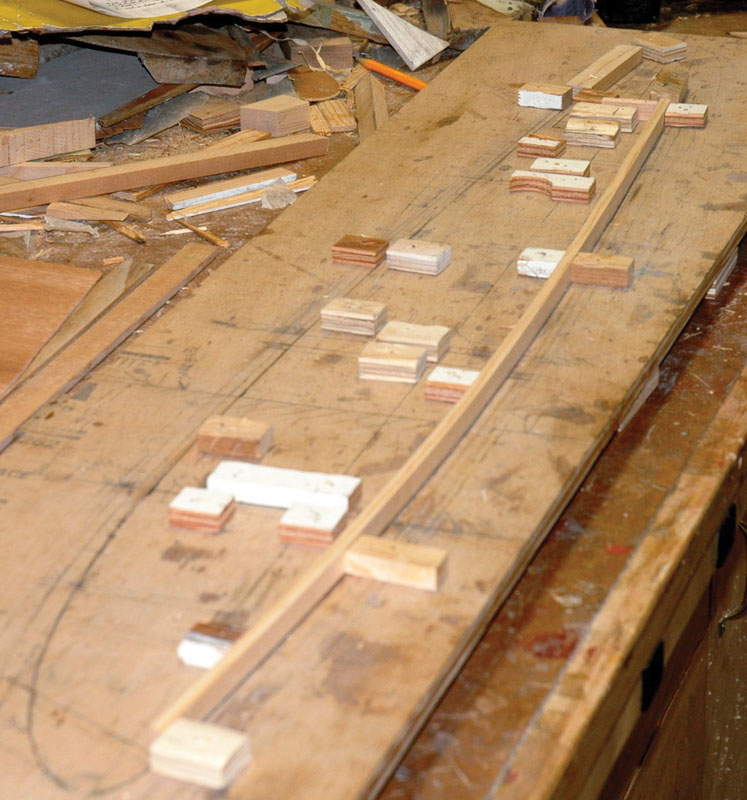
The baseboard that built all 28 ribs. The rib outline has been drawn onto the baseboard from the offsets. A cap strip is fixed in place, matching the curve on the board by bending it and holding the bend with a few blocks pinned to the board with 18-gauge pins. This is fast and easy, and once the rib is built, the blocks and baseboard can be reused. The technique requires a pin gun, an air compressor, and pins of the correct length to avoid nailing the baseboard to the bench. A pneumatic stapler will come in handy, too.
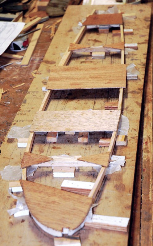
This rib is ready to come out of the jig. All glue joints have cured, and the 1/16-inch plywood braces have been added. The plywood braces were left large for later trimming.
Finally, the Plans
After struggling with the aircraft for about two years, I received a gift from Christophe Marchand, the French test pilot, in the form of a CD with all of Dalotel’s original drawings, including all the rib drawings. Each and every rib drawing had details of its contour in the form of a table of offsets. The rib drawings also showed the placement of the bracing sheets, made of 1/16-inch plywood, which do not cover the entire rib. To get the shape and size of each rib, you find a flat surface and draw a reference line that is basically the chord of the wing. Then, starting at the front, which is “zero” on the chart, you measure the given distance from the chart along your baseline and mark that point. Finally, you measure up and down from that longitudinal point, according to the up-and-down “y” dimensions given on the rib diagram, and mark those spots with a dot.
By continuing this process for all the offset numbers given in the chart you end up with a series of dots that, if you’ve done everything right, will fall on the contour of the rib. Connect the dots in a smooth curve, and there’s the rib outline drawn full size on your pattern. Once you have the outline of the rib, the next step is to add blocks to the baseboard to hold the cap strips bent to shape, and more blocks to locate the vertical joining pieces of the rib in place, then glue ’em all together.
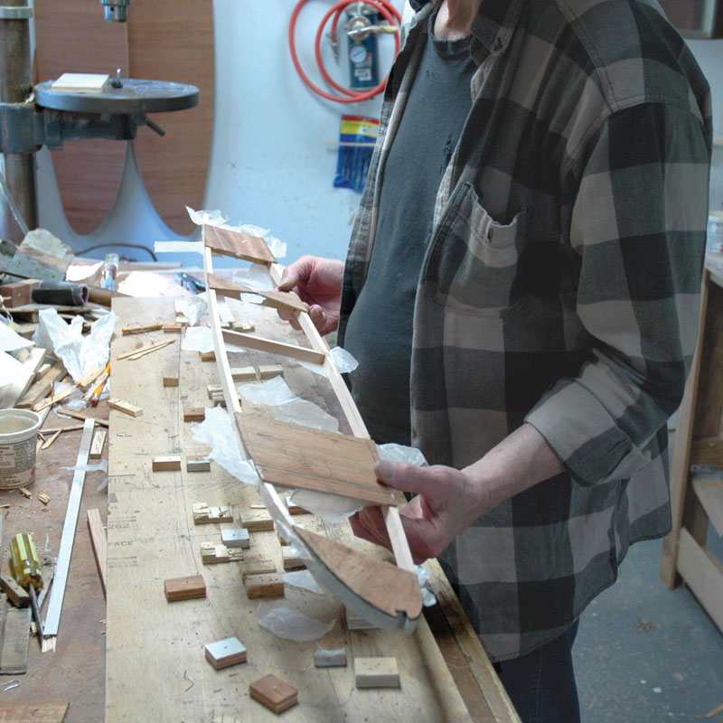
A rib is born. Fresh out of the jig, the rib has some extras attached. The waxed paper bits pull off easily. The overlapping bracing plywood will be taken care of with an edging router.
One would expect to have to build a jig or rib mold for each and every rib. That means I’d have, in the case of the Dalotel, 14 rib patterns on 14 large pieces of plywood, whose jigs would almost surely never be used again. Further, the plywood holding the 14 forms or molds would generally be useless because of all the blocks glued to it to shape the cap strips and position the joining members. That, however, was most certainly not the case for me. I came up with a system that was so extremely easy to build my ribs that I thought it would be a good idea to share it with the homebuilding community, in the hope that it might encourage others to build tapered wings.
A Better Way to Make Ribs
I began with the biggest rib, number one. It is nearly six feet long and about ten inches high. I needed a piece of plywood somewhat longer and higher than those dimensions to give room for all the blocks I was going to fasten to the board to hold the parts in place while the glue—in my case West System epoxy—cured. I used a piece of half-inch-thick plywood for my baseboard. In my shop I could easily support that relatively thin plywood baseboard so that it remained entirely flat as I built the ribs. If necessary, one could stiffen the baseboard with perpendicular braces or trusses behind it, or use thicker plywood.
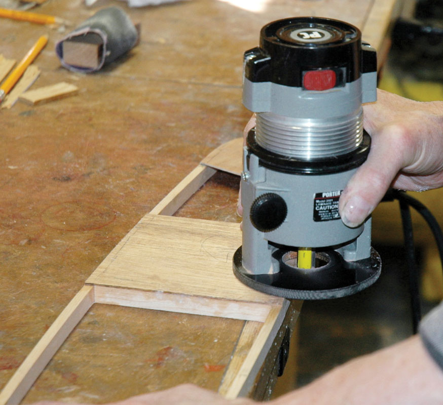
The router at work. There’s a ball bearing on the end of the cutter that rides against the cap strip. The result is perfectly trimmed edges in seconds.
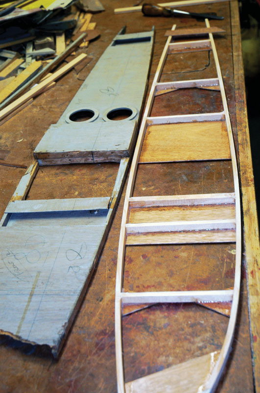
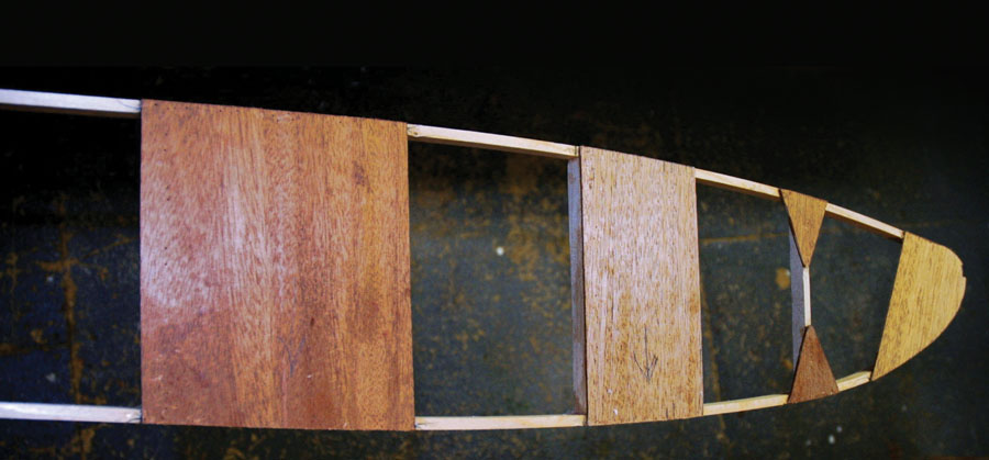
A new rib is shown next to the original, which had its nose smashed off in a hard landing. The author is about to put the covering plates onto the top side of the new rib, following the pattern of the original, and with a hard look at the rib drawing in the plans. There were some discrepancies between the drawings and the actual ribs. In such cases, the author matched the existing rib, not the plan. Note the holes in the original that will not be in the new rib. They were for control wires for a spoiler system that didn’t work and was locked out by the original builder. The restored airplane will not have spoilers.
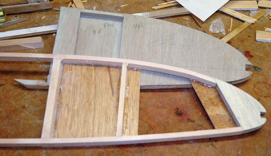
Here’s another rib that is about to have the “other side” put on, next to the gray original. The nose block on many of the ribs is balsa sandwiched between 1/16-inch mahogany plywood stiffeners. The bracing plates were on opposite sides of the rib on the right and left wings.
Next I drew a chord or reference line along the wood. This served as the baseline for all the dimensions of each and every rib to be built, and yes, I used only that one piece of backing plywood for all 28 ribs. The difference between right and left ribs is in the size and placement of all the 1/16-inch plywood braces, gussets, and panels glued to the side of each rib. Some were large, some small, and the only variance from left wing to right was that the large and small pieces were on opposite sides. When I built each rib, I put the appropriate braces on the upper side while the rib was in the jig; when the rib was cured, I pulled it off the jig and put the proper braces on the other side of the rib. I didn’t need a jig for the second side because the form of the rib was set and fully braced before it came out of the jig.
With a reference or baseline down the middle of my basic plywood jig, I went to the rib drawing for rib number one and laid out the offsets, measuring up and down from the baseline, and drew a small circle around each point. All the rib drawings resembled the drawing of rib number eight (see photo). The distance along the chord is given both as a percentage of the chord, and in “x” dimensions, starting from x=0 at the leading edge. The “y” dimensions are up and down from that linear distance along the baseline. All the dimensions on all the drawings of this airplane are in metric units. The simple way to get around that is to buy a metric retractable scale, which Stanley makes (Stanley 5M, 30-497). Or you can convert the dimensions—and risk mistakes.
Now that I had a series of dots indicating a curve, I used a cap strip as a French curve and bent it along the dots and drew a connecting line to show the outline of the rib on the baseboard. Although it was not necessary to connect the dots, seeing the outline of the rib made for easier adjustment as I bent the upper and lower cap strips and locked them in place. I also drew the locations of the connecting uprights onto the backing wood plate, cut them to fit precisely between upper and lower cap strips, and locked them in place with more blocks. I used a pencil for all the markings, so I could erase as needed as I went along.

The center unit is the 18-gauge pin shooter that held all the blocks in place. The other two are staple guns for securing the cover plates to the rib cap strips. Why two? You don’t want to be looking for the proper staples and fumbling with the reloading sequence when one gun runs out of staples and the epoxy is rapidly setting.
Adding Wood Blocks
I had prepared a bunch of wood blocks beforehand. They were about 1 inch x 11/8 inch and 3/8-inch thick. I wanted the blocks to be below the level of the cap strips, which on my ribs are 1/2 inch wide by 1/4 inch thick. Rib number one was thicker, but you get the idea. I placed these blocks on the backing plate inside and outside of the cap strip in a manner to force the flexible cap strip to conform to the correct outline of the rib. Once the cap strip matched the rib contour, I shot an 18-gauge pin from a pneumatic nail gun through the blocks that held it in place. Some blocks took two pins. The vertical joining members of the rib were also positioned with blocks attached in the same manner.
Once the top and bottom cap strips and the joining members were in place and the forward connecting wood block similarly positioned, I lifted each wood-to-wood joint and put a small piece of waxed paper under it so the assembly would not stick to the baseboard when the epoxy cured. Then, with the epoxy properly and carefully measured, floxed, and mixed, I glued each piece in place. There were no nails through any of the cap strips at this point, just a whole lot of small blocks holding it all in place. Except for the time to cure, which I set at 24 hours, this procedure took only a few minutes—not days—to make a permanent jig for each rib.
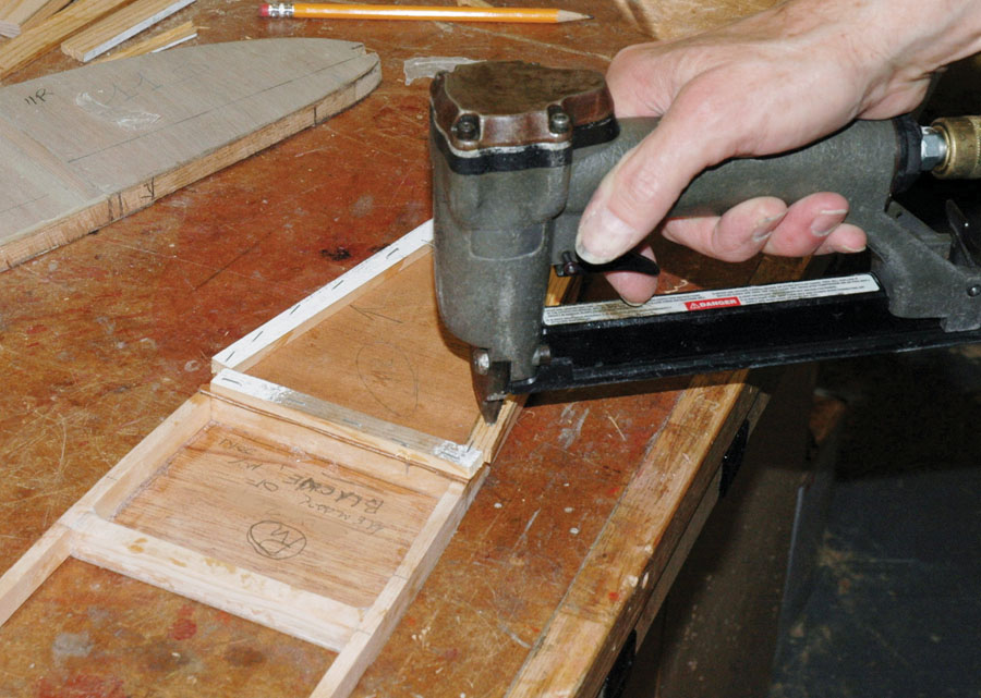
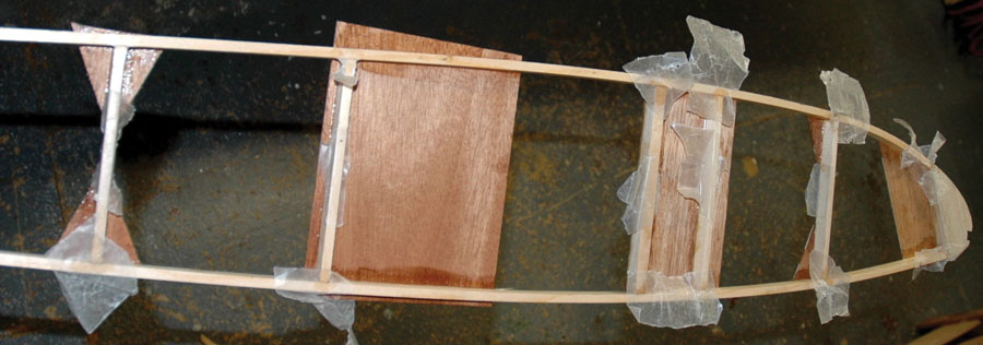
This pneumatic gun shoots staples through scrap wood, then through the covering braces and into the cap strip. This is an excellent way to make tight epoxy joints.
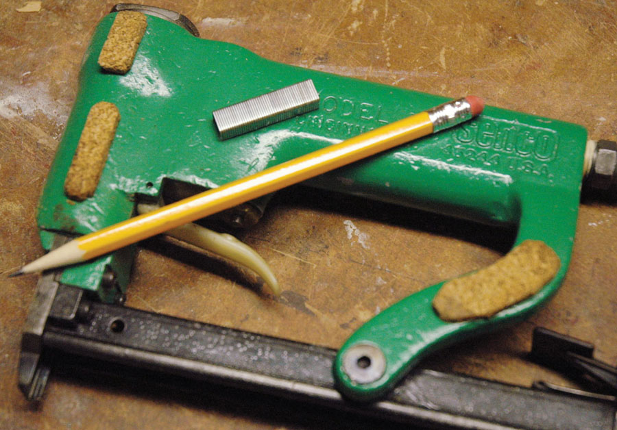
The staples are small to avoid splitting the spruce cap strips. Here’s a stack of ’em next to the pencil.
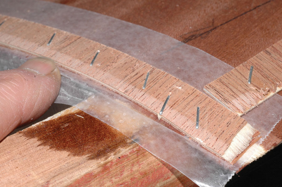
Here’s how the staples held down a big sheet of plywood covering the stabilizer of the airplane. This is a standard wood airplane construction technique.
The next day, with the rib still in the jig, I added the 1/16-inch plywood braces. The positioning blocks were below the level of the rib, so they didn’t interfere with the 1/16-inch bracing plates. Heeding the grain direction, I cut these to the right width, but I let them overhang the top and bottom cap strips, to be trimmed later. That way, there was no tedious shaping and no struggle to get them in just the right spot.

Here’s why you use scrap wood over the good stuff to staple it together. Removing the staples with a sharpened screwdriver and big pliers generally results in the destruction of the strips, but the important wood underneath is not harmed in the slightest.
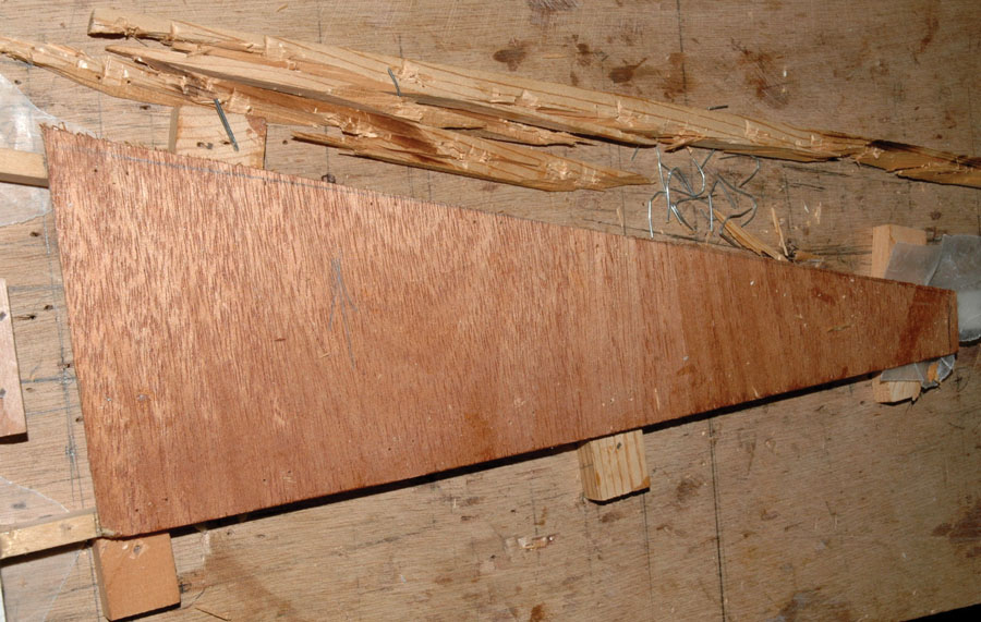
The undamaged good wood is shown next to the essentially destroyed protective cover pieces. With the plywood bracing plate bonded properly to the cap strips, all that’s needed is a few seconds with the router to get this rib ready for the braces on the other side.
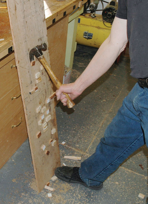
It’s a matter of a few minutes to remove the old blocks and get ready to lay out the next rib on the one and only baseboard used for all 28 ribs. Most of the blocks can be reused by simply pulling the pins through them.
There are several ways to secure these as the epoxy cured. One is to add weight, but the brace can shift if you do that. A better and more controllable way is to use accurately placed staples from a pneumatic stapler shot through the plywood bracing plate into the underlying spruce stock. I never staple directly to the part being glued for several reasons. I used a strip of scrap plywood or spruce along the staple line of the cover plate. The staples were shot through the scrap, then through the good plywood, and then into the cap strip underneath. This made it easy to remove the staples after the epoxy cured without gouging the good wood of the thin stiffening plate, and the stables don’t get glued to the good wood. The staples were of light gauge to avoid splitting the spruce. When these cured, I popped out the staples with a sharpened screwdriver and pliers, and removed the rib from the jig.
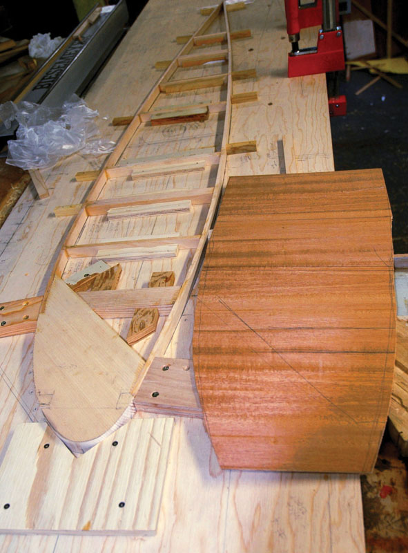
This is the first rib built on the baseboard, number one. It’s thicker and heavier in all its dimensions, and required a slightly different technique from all the others, but it proved the concept of using one board, a pneumatic nailer and stapler, and ingenuity to make building tapered ribs easy.
Trimming
I was then able to trim the overlapping reinforcing plates with a small router, using a ball-bearing-style edging bit. The ball bearing rides against the cap strip, while the cutter removes all the overlapping plywood. This was fast, very accurate, and worked like a champ. Then I could add the necessary covering strips to the other side of the rib, use my jig to make a second rib for the other wing, and then go on to the next pair.
To prepare the baseplate for the next set of ribs, it was a matter of a few minutes to simply pull all the blocks off my baseplate with a hammer. I could reuse the blocks once or twice by pulling the pins through the block. Each pair of ribs was smaller than the previous pair, so the marks were easier to see and the supporting wood was essentially fresh and unused. As noted, I had laid out the positions with pencil and could erase my marks easily if they got in the way of the next setup.
This was an extremely efficient and simple way to make tapered ribs. Now I have all the ribs needed for this immense restoration project. One set is already in place on the repaired spars of the left wing. I still have to make the spars for the right one, but that does not appear to be a huge job because I’ve got it all doped out how it’s built. I split the old main spar completely down its middle to see what was inside, and now that I have the plans, I can see precisely how I’m going to make it. Right now, I’m in the middle of figuring out the new setup for the retractable landing gear and making parts for the gear mechanism. The landing gear had stymied me for over three years because the original wheels and tires were no longer available. Now, thanks to products from Beringer Aero and a slight redesign, I can see the light at the end of that tunnel.
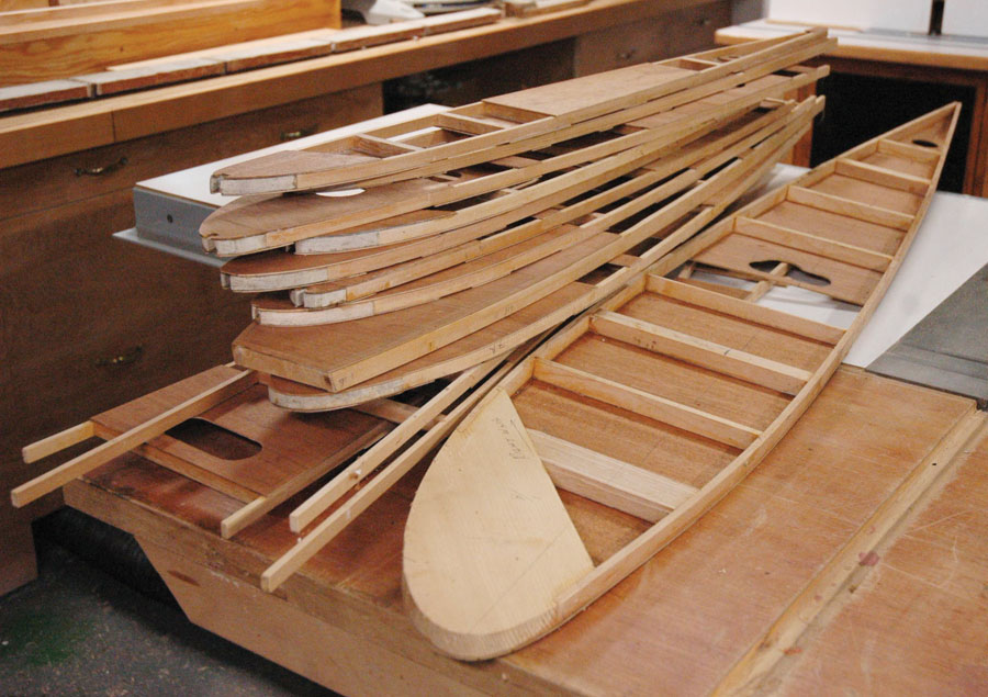
This is the stack of 14 ribs for the right wing, which needs a couple of spars, some tricky inletting, covering, and one or two other little bits.



My name is ken
I am looking for the size for a rib. What is the length and Hight. I can not find a template for a rib.