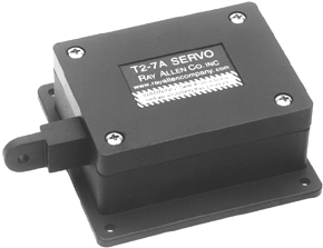
 We left the end of the annual with a note about problems Ive been having with the electric pitch trim system in my Glastar Sportsman. For background, the Sportsman has what has become a fairly common setup among homebuilts. A small electric motor-a Ray Allen Co. T2-7A, to be specific-is connected directly to a movable tab for trim. The Sportsman has one small tab on the right aileron for roll trim, and one large tab on the trailing edge of the elevator for pitch. Flick a switch, the servos arm moves, and you’re back in trim again.
Inside this compact servo package is a small DC motor, a linear potentiometer to provide trim indication feedback, and two limit switches that stop the motor at the end of the trim arms travel. The motor drives a steel jackscrew through a set of nylon gears.
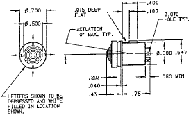 There’s actually more to the electrical part of the system. In my airplane, both control sticks have four-way switches under what, in a lesser PC time, were called coolie hats. These switches cannot carry a great deal of current; in fact, Ray Allen rates this switch (the ROS-4) at just 1 amp. The theoretical maximum current use by the servo, when the engine is stalled, is 600 mA. Pretty close. The nominal current use is just 150 mA. So its unwise to use the ROS-4 switch to carry the primary servo current. Its also become common to avoid running a hot 12-volt wire into the stick, so what the ROS-4 does in this installation is bring one of four wires to ground. Finally, because the ROS-4 is a really just a four-way single-pole, single-throw switch-think of it as four separate circuits, each one taken to ground when pushed-it wont work the servo directly. The Ray Allen setup simply has the positive and negative servo-power leads reversed depending upon which way you want to drive the motor.
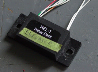 Phew. OK, then. Because of all these requirements, there’s one more: a relay deck. When my Sportsman was built, the REL-1 was the relay deck of choice. Its job is to take commands from the stick switch and send 12 volts in the right direction to the servo so it moves the way you want it to. The REL-1 connected two wires to the stick, one to bus voltage, one to ground and two back to the servo.
Now, for my airplane’s problem. The trim system began exhibiting a dead spot. It would trim nose-down from the takeoff setting to cruise, but, over time, began failing to trim in the nose-up direction. Through experimenting, I discovered that if I trimmed more nose-down, I could get the servo to trim nose-up again. But, as it got worse, it took more movement in the opposite direction before the servo would move the way I wanted it to.
So troubleshooting began. I could hear the REL-1 relay deck clicking when I moved the stick switch. That part of the circuit was good. I checked the wiring to the tail and put a voltmeter on the motor itself. Twelve volts was there when the trim system was moving, but it dropped to 3 to 4 volts when the system would not move. Hmmm. That meant the relay was working but the motor was asking for too much current-or so I thought. The inside of the servo was clean, but I lubricated the jackscrew anyway. It seemed to work-problem solved.
Or so I thought.
Two flights later, the problem was back. Running out of bright ideas, I asked other Glastar owners on the Glasair Aircraft Owners Association forum. Almost immediately I found out that this is a common problem, and the cause was not the motor but the relay. Seriously? One poster suggested I call Ray Allen for the straight poop.
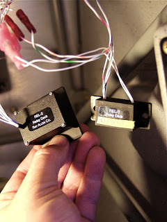 Good advice. The Ray Allen rep said, in effect, yep, the relay is bad. The contacts were rated for 1 amp, but sometimes the company would get the relays in for inspection and the contacts would be dust. Now it made sense: If the contacts are shot, once the current rose above a certain level, the connection was partially lost and the voltage dropped to where the motor would not run.
The solution was a new relay, not just a replacement. The old REL-1 isn’t even on the company’s web site, replaced by the REL-2. I was told the new relay could handle something like 10 amps, which ought to be more than enough for the 600 mA trim motor.
An hour or so fumbling under the panel and the new relay is in. (Sorry to say its mounting flange is narrower than the old one, so its not a screw-out, screw-in mechanical replacement.) Time will tell if this is a long-term fix, but word from Glastar owners is that it ought to do the trick.
The bigger lesson is this: Don’t think you know all the answers when something seems logical enough. Because I could hear the relay clicking, I assumed it was not at fault and began focusing on a part of the system that wasn’t broken. In fact, before I had come to my senses, I had ordered a new trim servo from Aircraft Spruce. Im much happier replacing a $46 relay pack than a $140 servo.







It goes beyond the rated load. A DC motor is an inductive (and resistive) load and as such there will be a voltage spike when the relay opens, which is does many, many times. That is much more damaging than established current.