Measure twice, cut once. That’s sound advice, though no guarantee you won’t measure wrong twice. Some measuring errors occur before the ruler is in hand, while interpreting plans. Other errors spring from the physical tool and others from how a ruler is employed. A builder’s success can also fall to the mercy of kit documentation; designing and drafting are different skills (an engineer told me he got his degree without a single drafting class) and blueprint reading, once taught in middle school, is a dying skill. I digress.
Plans Accuracy vs. Part Accuracy
Before CAD, human hands and eyes drew blueprints for human hands and eyes to interpret into parts. Now computers “draw” parts for CNC machines to make. This technology ushered in the matched-hole era of homebuilding, but came with a side effect; worried builders. Builders worry over the apparent need for precision as expressed by the dimensions on plans. Spar’s that need to be 6-29/64” tall. Fittings that bear a 7.2-degree bend. (Don’t get me started on plans that use decimals instead of fractions of an inch.) In nearly every case the precise dimensions spring not from need but from the auto-dimension menu setting in a CAD program. Many Sonex Aircraft drawings were auto-dimensioned to a resolution of 1/64-inch and 1/10 of a degree, when 1/32-inch and whole degrees would have been plenty accurate.
When presented with such fine-resolution dimensions it can be hard to know when a dimension is critical. I can’t provide a one-size-fits-all answer, but I can say the larger the over-all dimension the less critical the accuracy. If a part is 92-59/64-inches long and you muff it by 1/64-inch, even 1/32-inch, you are still accurate to within tens-of-thousandths of a percent. Sonex Aircraft plans are co-dimensioned with metric units. 92-59/64-inches is 2360-millimeters. That’s a comforting, round number to fall back on. No one can employ standard measuring tools to mark, cut and debur/sand to within 1/64-inch, nor should it be necessary. If it is, the design probably shouldn’t be in the hands of amateur builders.
Another way to estimate the importance of a dimension is to ask yourself, “What is this for?” If it’s a clearance hole for a rudder cable or a wing inspection hole it probably doesn’t have to be located or sized to an accuracy of more than 1/16-inch, which is easily achievable.

Tool Accuracy
A story was shared with me that a kit manufacturer’s fabrication department was passing parts to its assembly department, where fitment issues were found. Drawing or human error were suspected but the cause was an inaccurate ruler drifting about the fabrication shop. A technology-based equivalent to an inaccurate ruler is a printer/copier that shrinks or enlarges an image, rendering a “full size” drawing or pattern inaccurate. (Though no dimensionally-critical parts should be defined by un-dimensioned, “full size” drawings.)
While an incorrectly marked ruler is likely rare, damaged rulers are not. I never use the end of a ruler if it is trimmed to the “0-inch” mark. My concerns are: If it’s brand new, has it been cut correctly, and if its old its end is likely battered. To avoid the questionable ends of rulers I measure from the 1-inch mark, remembering to add one to my over-all measurement. Thus, a 9-11/16-inch measurement must be marked at the 10-11/16-inch line. Admittedly, this creates its own opportunity for a measuring error, which can be eliminated by measuring from a ruler’s 10-inch mark; 12-3/4-inch becomes 22-3/4-inch.

Tolerance Creep: The Enemy of Accuracy
Tolerance creep is the accumulation of measuring errors (or, more likely, marking errors) which, over a distance, can place cuts, bends and holes out of position. For instance, if you mark a row of 64 holes spaced 1-inch apart by marking each hole’s location from the previous hole, and you are just 1/64-inch long with each hole’s location, the last hole will be one full inch out of position.
Preventing tolerance creep begins with the airplane’s documentation. Properly executed drawings dimension key features from a single reference point. While that can make for a busy drawing (which can give some the impression the part is difficult to make), it assures a more accurate part is produced. You may still be off 1/64-inch on each hole’s location, but there is no cumulative effect.
Another method used for dimensioning a series of equally spaced holes—a method which reduces the clutter of multiple dimensions—, is a statement such as “24 holes spaced on 1-inch centers.” A builder need only lay a ruler or yardstick on the material and make a mark at each inch increment
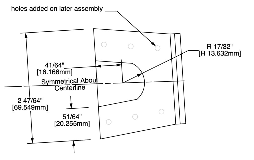
Radius vs. Diameter
The way curves and holes are defined in plans and subsequently translated by a builder can be a source for error. Be aware if the plans are identifying a radius or a diameter. A radius is typically identified with a capital “R” or the abbreviation “Rad.” A diameter is typically identified with a capital “D,” the abbreviation “Dia.”, or the symbol ⌀. Here’s a hint: complete circles and holes are typically defined by their diameter, arcs by their radius.

Miscellaneous Measuring Methods
All units of measure are made up. The inch was defined in the 14th century by King Edward II as being equal to three grains of barley placed end to end. The meter was defined in 1791 as 1/10,000,000th the distance along the Paris meridian from the north pole to the equator. Transferring or checking a length or distance can be as simple as making two marks on a piece of paper, using the width of a washer or eye-balling the centerline on a rib.

Conclusion
Almost all measuring mistakes spring from assumptions or hurried effort. Take your time to be sure of both your interpretation of the plans and your measuring technique. A few added moments (sometimes minutes) of thought can prevent a time-consuming, possibly expensive, error. You don’t need to measure twice if you measure correctly once.


