How much of a motivational tool would it be to be able to simulate flying your homebuilt long before it was actually completed? Using the X-Plane flight simulator, you can do exactly that: build and fly a computer model of any airplane.
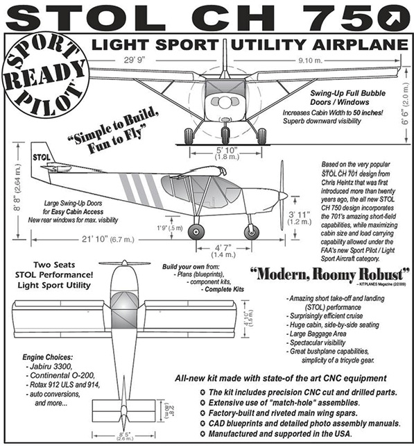
One of the first things you need to make a model is drawings of the airplane. These were found on Zenith’s web site (www.zenithair.com) along with the dimensions and performance specs.
Laminar Research’s software is actually a package of four programs: Plane-Maker is used to build models; Airfoil-Maker is used to specify the lift and drag characteristics of airfoils; X-Plane is the program used to fly the planes; Briefer gives a weather briefing using real data from the Internet and flight time for any plane among more than 25,000 airports.
The system works by dividing the model into hundreds of small areas, calculating the aerodynamic forces on these, adding them up and then using fundamental physics to determine the behavior of the plane. With good input, this usually results in accurate predictions of how an actual ship will fly. This article will show you the results, but not the details of how to use the programs included in the X-Plane manual. Let’s try it out using the STOL CH 750 from Zenith Aircraft.
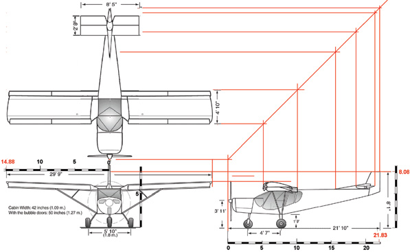
The drawings can be used as “backgrounds” in Plane-Maker, but should be checked against each other for consistency of scaling.
Plane-Maker
Plane-Maker is a computer-aided design program specialized for X-Plane modeling and is included with the $29 package from www.x-plane.com. The program understands the fuselage, wings, engines, landing gear, etc., and most of the more important information required can be found on the kit manufacturer’s web site. Many other details can be filled in by contacting the company directly, but an educated guess may be necessary to fill in any data that you may be missing.
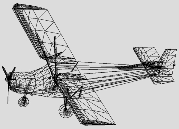
Using Plane-Maker, a “wireframe” is constructed. Although there are many parts when the wingstruts are included, this is relatively easy because of the simple lines of the CH 750.
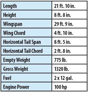
Table A: Critical data for the Zenith CH 750.
The plan view and the dihedral of the wing and tail are drawn in Plane-Maker, as are the extent and movements of the control surfaces. The CH 750 has flaperons, where one control surface does the work of both flaps and ailerons. In Plane-Maker, flaperons are specified by "ailerons with flaps" on the Special Controls screen. The flaperons are in two sections along the wingspan. The inboard part is a little lower than the outboard. The result is to provide the effect of wing twist without twisting the wing; the inboard wing stalls before the outboard part so that aileron control can be maintained. While Plane-Maker cannot lower part of the flaps, it does allow for two sets of flaps, each with different characteristics. I simulated this by giving the inboard flaperons a bit more lift coefficient (CL) and drag coefficient (CD) when extended.
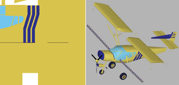
| A file named “CH-750_paint” is used to apply texture to the wireframe. Each part can be assigned to any area of the file. | This picture shows the various parts after they were painted. |
If flaps are down to 15 and the pilot then commands ailerons to roll to max 13 deflection, one of the flaperons is then lowered to 15 + 13 = 28, and the other is at 15 – 13 = 2. The lift and drag characteristics of the airfoils are set by Airfoil-Maker.
Plane-Maker has the ability to use more than 300 stock instruments, buttons and handles to design panels. You can modify the appearance of any of those and create custom ones as well. You may not find exact matches in the way they look and operate, but the fit will usually be close enough.

Table B: Zenith provided data on the airfoils.

Table C: Direct communication with Zenith Aircraft provided the control-surface deflections. Flaps are electrically controlled over the whole 15 and have no detents.
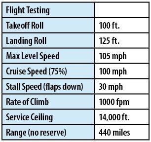
Table D: These performance specs from the Zenith web site were used to check the viability of the model.
Airfoil-Maker
X-Plane represents airfoils that can be created or modified with Airfoil-Maker, which also comes with the package. There is a library of airfoil lift and drag coefficients as functions of angle of attack, and the NACA 0012 is included. Airfoil data is stored as text files with names like "NACA 0012.afl." These files contain the shape of the foil and long tables of CL, CD and moment coefficient (CM) for angles of attack ranging from -180 to +180. By entering parameters in Airfoil-Maker, you can change the shape of these three tables over AOA from -20 to +20. When you save the file, the program makes a reasonable estimate for the data from -180 to -20 and from +20 to +180.
The horizontal stabilizer has an inverted airfoil because of the need to keep the tail down at high angles of attack. The NACA 4412 data is available from sources such as Theory of Wing Sections by Abbott and von Doenhoff. In creating a new airfoil file, Airfoil-Maker accepts data only for angles of attack between -20 and +20. The program fills in the rest of the full range. This process is reasonable for airfoils that stall at angles of attack less than 20 and may be acceptable for the stabilizers. The real challenge is to model the airfoil for the wing.
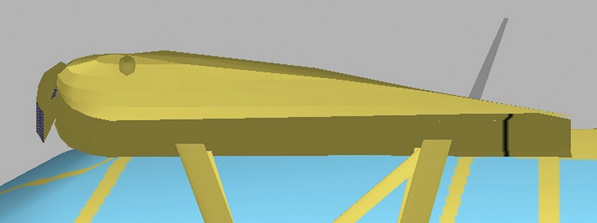
The slat on the leading edge of the wing is an X-Plane “misc body.” It is specified to have zero drag and does not participate in the aerodynamics of the wing itself.
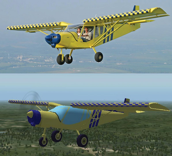
The model bears a good resemblance to the real airplane.
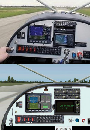
A working replica of the panel can be created in Plane-Maker.
Zenith modified the NACA 650-18 foil by adding fixed open slats on the leading edge and by stretching aft of the quarter chord point. This is probably why the thickness is less than 17% instead of 18%. Here is a summary of the information from Zenith about the characteristics of the wing:
For the linear portion of the CL (coefficient of lift) versus AOA (angle of attack) curve:
CL = 0.075 x (AOA – 4.2) with no flaps
CL = 0.075 x (AOA – 13.5) with full flaps
CLMAX = 2.25 with no flaps
CLMAX = 2.95 with full flaps
The drag coefficient is made up of two parts: skin friction and form, and that which is induced by the lift (CDO is drag coefficient at zero lift, and CDI is induced drag coefficient).
CD = CDO + CDI
CDI = CL2 / (π AR e)
Where AR is the wing area ratio and e is the Oswald’s efficiency number (Oswald’s efficiency, similar to the span efficiency, is a correction factor that represents the change in drag with lift of a three-dimensional airplane wing, as compared with an ideal wing having the same aspect ratio and an elliptical lift distribution.) For the Zenith CH 750, span = 29.75 feet, and chord = 4.83 feet. So AR = 29.75 / 4.83 = 6.159. Then CDI = CL2 / (19.34 x e) x Oswald’s efficiency is equal to 1.0 only for elliptical wings, so let’s use e = 0.9. Then CDI = CL2 / 17.41. There is actually little information available about CDO, but I settled on 0.032 with no flaps and 0.075 with flaps. The lift moment coefficient (CM) was assumed to be constant -0.046 over the entire AOA range of interest.
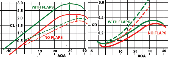
On these charts, data for the wing airfoil is shown with solid lines. The dashed lines represent CL and CD for the whole airplane whose values were obtained by flying the model. As angle of attack increases, whole-body lift decreases and drag increases relative to that of the wing itself.
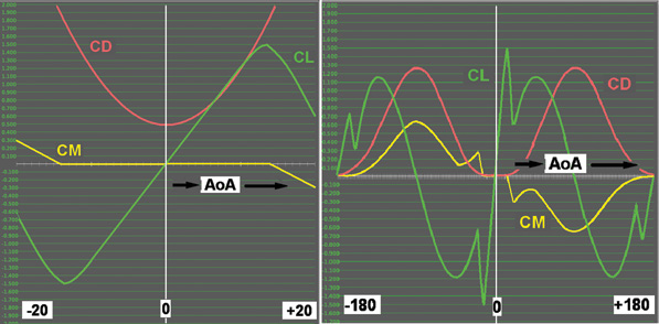
Airfoil-Maker allows you to work within 20 on either side of zero angle of attack and then fills in the rest of the full range for you. This is data for the NACA 0012.
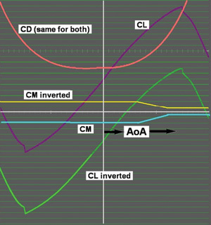
Inverting an airfoil requires that the lift coefficient be reduced by an amount equal to twice the value at AOA = 0. The moment coefficient must simply have the algebraic sign changed at each value of angle of attack. The drag coefficient is not modified.
Airfoil-Maker will not allow you to specify data outside the +/-20 range in angle of attack, so some other method must be used:
Use Airfoil-Maker for the +/-20 range.
Save the results as wing20.afl, which is a text file.
Import wing20.afl into a spreadsheet program such as Excel.
Carefully manipulate the data between 20 and 40 AOA. (This can be done by trial-and-error curve fitting.)
Save the data as NACA 650-18.aft, again as a text file.
The data that Airfoil-Maker supplies outside -20 to +40 AOA will not be realistic, but the plane is not likely to fly under those conditions anyway.
X-Plane uses airfoil data for "no flaps" and then adds the difference between "flaps" and "no flaps" as the flaps are lowered. In this case, CL increases by 2.95 – 2.25 or 0.70, and CD increases by 0.075 – 0.032 or 0.043 as flaps are lowered to their full down position. There is another change as flaps are lowered: The angle of attack for maximum CL moves to a lower number, but X-Plane does this automatically.
Zenith designer Chris Heintz has written an informative article about high-lift airplanes. You can read the full text at www.zenithair.com/stolch801/design/design.html.
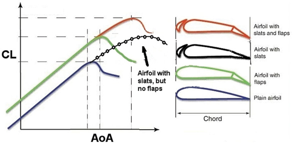
The case of “Airfoil with slats, but no flaps” was added to this figure from Chris Heintz’s article about high-lift airplanes.

