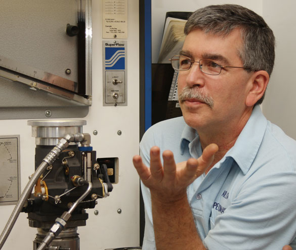
For the first half of Saturday we sat in a small classroom and were spoon-fed an easily digestible diet of fuel injection system theory by Don Rivera, the head cheese at Airflow Performance Incorporated (API). We were here to learn about fuel injection in general and the company’s system in particular, and this part of the curriculum provided the necessary primer for what was to come.
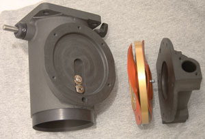
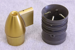
The key to understanding fuel-injection theory is Bernoullis principle, which states that with an increase in the velocity of a fluid there is a resulting decrease in pressure. The bullet-type venturi in the throat of Airflows fuel control increases the velocity of the airflow through the control. A perfect fuel-metering system would measure mass airflow, but velocities-which are much easier to measure-are related closely enough to mass airflows to be usable for fuel-metering purposes, Rivera explained.
By constant referencing to the airflow velocities and balancing them against fuel pressures, the regulator section of APIs fuel control maintains the fuel-air ratios required to support combustion for all power settings. During the classroom session, Rivera defined terms such as metering head (MH), which is the differential pressure, or pressure drop across the fuel-metering jet. The before-jet pressures are applied to one side of the fuel diaphragm in the regulator section of the fuel control; the after-jet pressures are applied to the opposite side of the diaphragm. Increases in the MH decrease fuel flow.
Metering suction differential (MSD) is the differential between ram air pressure and venturi pressure. These pressures are applied to opposite sides of the air diaphragm in the regulator. The MSD is always trying to open the fuel regulator ball valve, which will increase fuel flow.
Rivera tied together the importance of MSD and MH when we learned jet theory, which states that doubling the fuel flow through the fuel jet creates four times the MH. Venturi theory states that doubling the airflow creates four times the MSD. Fuel pressures are greater than the air pressures, so the dynamic area of the air diaphragm is considerably larger than the dynamic area of the fuel diaphragm. The two areas are proportioned so that when the engine is operating at a fixed throttle-valve setting, the forces generated by the two diaphragms are balanced, and the fuel flow is steady.
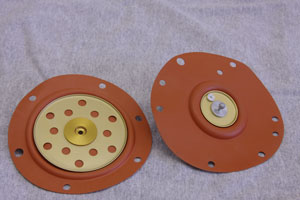
The two diaphragms in the Airflow unit are connected through a small-diameter steel shaft with a regulator ball on one end; the other end extends through and is secured to the center of both the fuel and air diaphragms. Changes in MSD and MH cause changes in the position of the respective diaphragms, prompting movement of the regulator ball in relation to a fixed seat. During normal cruise power settings the regulator ball moves from 10 thousands (0.010 inch) to 20 thousands (0.020 inch) off the seat. The fixed seat can be shimmed to fine-tune fuel flows.
In Action
As Rivera explained, throttle movement causes a change in MSD, shifting the air diaphragm, which is almost instantly transferred through the shaft to the fuel diaphragm and the regulator ball, resulting in a change in fuel flow.
For instance, when the pilot opens the throttle valve, airflow increases, causing a change to the MSD. Remember that the forces generating the MSD are from the venturi, which generates signals that react almost instantly to throttle-valve changes, and impact air, which varies with changes in atmospheric pressure (altitude and to some degree, temperature). This change in MSD causes the forces in the regulator to go out of equilibrium as increases in the valve-opening force generated by the air side of the regulator drive the regulator ball to move off the seat, allowing more fuel to flow to the engine.
As fuel flow increases, the fuel MH pressure increases, driving the fuel diaphragm to close the ball regulator valve until the MSD across the air diaphragm and the MH across the fuel diaphragm again achieve a state of equilibrium. The same thing happens in reverse when the power is reduced, Rivera said.
In addition to the physics lesson, we got to examine parts such as the fuel and air diaphragms, which are made of Dacron/fluorosilicone material. (Rivera claimed he had never seen an API diaphragm leak.) We also checked out other parts such as fuel-injection nozzle bodies and calibrated restrictors, bullet venturis and constant-effort springs.
After patiently taking time to make sure everyone understood the theories of Fuel Injection 101, Rivera took us 10 feet down the hall to the company lunchroom, where we were treated to a delicious meal whipped up by his wife, Colleen. The class consisted of only three people-Ken and Melinda Harrill of Columbia, South Carolina, and myself-so everyone had ample time to get better acquainted, enjoy lunch and tell a few flying stories.
Back to the Bench
After lunch we headed for the fuel-flow and airflow benches where we saw our newly absorbed theories demonstrated. We varied airflow rates through a fuel control to produce MSDs of 0, 1, 2, 5, 10 and 15 inches of H2O. Fuel flow manometers located adjacent to the airflow machine tracked fuel flows and showed how the installation of different constant-effort springs (CESs) affect transition range fuel flows.
At lower air speeds, between idle and approximately 1200 rpm for normally aspirated engines, the airflow past the venturi isn’t sufficient to generate a stable MSD. The small CES inside the air-metering section generates an artificial MSD in the fuel-metering equation. Different sizes of engines and how they’re used (airshow aerobatics, etc.) require different fuel-delivery profiles during the transition between idle and normal operating speeds. Different sizes of springs are installed to customize how the engine takes the throttle out of idle.
We conducted airbox tests to determine the importance of installing a properly shaped and designed air inlet upstream of the fuel control. After the removal of an API inlet, one bench test showed the carb loss increased by 23%, and fuel flow increased by 6%. Carb loss is defined as the airflow pressure drop when measured across the fuel control inlet and outlet.
Rivera also spent time explaining the flow divider system and the details of API fuel-injection nozzles. These nozzles are the two-piece type. The nozzle body is installed in the cylinder head with the air-bleed hole up. Calibrated restrictors are then inserted into each body. The company makes a wide selection of restrictor sizes that permit very fine tuning of cylinder fuel flows. This fuel-flow matching process is known in the certified world under the GAMI name (for General Aviation Modifications, Inc., the product is known as GAMIjectors). Airflow provides this service at the factory in Spartanburg, South Carolina, for $300. Rivera demonstrated it by changing two nozzle restrictors in Randy Galloways RV-6 on Sunday afternoon.
The Early Years
After graduating from college Rivera went to work for Bendix, where he learned the RSA fuel-injection system from Elmer Haase, the developer. The term RSA is a more specific name for a range of mechanical injection systems developed by the company, often referred to simply as Bendix. Rivera is the kind of guy whos beholden to those who have influenced his life, so there’s a photograph of Haase posted in a position of prominence in the entry of the company lobby.
While working at Bendix in South Bend, Indiana, he met and married Colleen, who also worked there. In 1988, after moving the company to Jacksonville, Florida, Bendix sold the fuel-injection system line to Precision Airmotive of Everett, Washington. Rivera stayed in Florida for a few years, leveraging what he had learned during his Bendix years as he developed his own system-one that incorporates changes that address what he felt were RSA system shortcomings.
For five years Rivera worked at various non-aviation jobs, applying his fuel-metering knowledge and fine-tuning his design by installing it on motor sports applications such as dragsters, speed boats, Bonneville speed record attempts and road racing. Little by little, he improved his system.
Tunnell Vision
The fickle winds of fate intervened in 1991 when Kenny Tunnell, well-known high-performance aircraft engine builder and owner of Ly-Con Aircraft Engines in Visalia, California, told his client, Sean D. Tucker, that he wanted to put a new fuel injection system on the engine of Tuckers airshow airplane. Tucker agreed to give it a try, was impressed and started telling other airshow performers.
After the move to Spartanburg, API operated out of a corner of a warehouse for nearly a decade. In 1991 the company completed construction and moved into a new shop/hangar at the Spartanburg Downtown Memorial Airport (KSPA).
The API Team
Don and Colleen don’t have children, but they have Tigger, the guard cat, who rides back and forth to work with them in the car each day. They also have Kyle Day, ace technician and all-around team guy-whos 33 years old and seems permanently stuck in the joys of boyhood. Hes worked for Don and Colleen since he was 19. Day was two years into an electrical engineering degree and working part time at API when Rivera asked him to join the team full time. Day left the classroom behind and has never regretted it. Hey, man, how could I pass up having so much fun? he asked, punctuating the question with his trademark grin.
Adriane Delaney, who just celebrated her 21st birthday and has been part of the Airflow Performance team for two years, helps out in the front office.
In addition to building, calibrating and overhauling its fuel injection systems, API is also an FAA repair station for Bendix fuel-injection systems, but it doesn’t do many. They’re not our favorite thing to do, Rivera said.
I visited the facility before class officially started, and Day showed me around the shop. The airbox tells everything, he shouted above the roaring sound of the airbox as it pulled air through a control being tested, reaching over to tap on the side of the control (also called the servo, servo regulator or fuel injection unit) with a screwdriver to simulate vibration. Day said each fuel control is tested on a flow bench to ensure that it delivers the proper flow at different throttle settings. The company then installs each unit on an airbox, which pulls air through each control.
An engine is really an air pump, Rivera said, pointing out that each of the airboxes is capable of pumping 600 cubic feet per minute or 2400 pounds of air. Thats sufficient to simulate a 480-horsepower engine, he added.
The fuel control being tested doesn’t know its not installed on an engine. By increasing the airflow in steps and charting the fuel flow at each step, the performance of the control is verified. Each API system is shipped with a fuel-flow chart derived from airbox testing.
Product Refinements
To succeed as a small company, clever engineering must be mated with a practical approach to cost controls. To that end, Rivera has tried to make his product as much of a true building block scheme as possible. All four of our systems, from the small FM-100 for 80 horsepower engines up through the FM-400, which works for a 1000-horsepower engine, use the same regulator. Ive tried to make this system as universal as possible, he said.
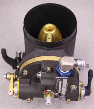
The four systems, the FM-100, FM-200, FM-300, and FM-400 differ in the size of the throttle body, which consists of a mounting pad for the regulator, the butterfly-type throttle valve and an airflow metering venturi. The throttle body, a bullet-type venturi, and the fuel regulator are assembled to form the fuel control or servo.
Airflows bullet-type venturi allows a greater mass airflow through the throat of the throttle body than the sidewall type, Rivera said. Because airflow is directly proportional to horsepower, it’s important to keep losses to a minimum.
Number One with a Bullet
According to Rivera, the API venturi reduces carb loss by a factor of three compared to the sidewall-type. There’s a second important factor: The API system has what Rivera calls a high-gain venturi. He says the sidewall-type venturi has a gain of two, while the API system has a gain of five. Reduced carb loss and increased gain improve the sensitivity of the API system, making it very responsive to airflow changes. The high-gain signal also means that G forces have less effect on the diaphragm plates during high-G aerobatic maneuvers. This system reacts quickly to abrupt throttle changes, he said.
More Valves: Mixture and Purge
Familiar with the scoring, fuel varnish and gum buildup problems in RSAs rotary-plate mixture control, Rivera designed something markedly different. As we learned in class, the API mixture control is a rotary-tube design. As the pilot moves the cockpit mixture control handle toward full rich, the mixture tube rotates in the body housing, allowing at first a trickle of fuel and then full fuel flow into the fuel-metering section. This rotating-tube type of mixture control has a lot of bearing area, so its not prone to wear, nor does it tend to get gummed up. These benefits are offset by a single drawback: Unlike the RSA mixture control, the rotating-tube type doesn’t completely shut off the flow of fuel to the engine when the mixture control is pulled back to idle cut off (ICO). That is the job of the purge valve.
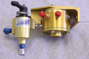
The API purge valve is a simple three-way valve thats mounted on top of the engine in the metered fuel hose between the fuel control (servo) and the flow divider (spider), Rivera said. During normal operation fuel flows through the purge valve to the flow divider, and then out to the individual injector nozzles. API-equipped engines are shut down by pulling a cabin control knob connected to the purge valve. The mixture control is left in the full rich position. This diverts fuel from the flow divider to a port in the valve labeled return, cutting off fuel flow to the engine so that it shuts down cleanly.
Rivera also explained why fuel-injection systems are plagued by hot-start woes. Avgas boils at 130 F. After a hot engine shutdown, fuel in the fuel control, fuel pump, metered fuel lines, flow divider and fuel injector nozzles is hot enough to boil. This results in gaseous fuel vapors and hot fuel in the system, and gaseous fuel is difficult to pump. Without a way to replace the vapor and hot fuel with cool liquid fuel, engine starts are problematic. Pilots often grind away on the starter while the engine acts like its going to start but never quite does. This can go on until the battery dies. The alternative is to purposely flood the cylinders with excess fuel and slowly pull the throttle control aft while grinding away, hoping to eventually arrive at the fuel-air mixture that will support continuous combustion.
When the API purge valve is moved to the return position, it not only cuts off fuel flow to the cylinders, but also provides a pressure bleed path for the boiling and expanding hot fuel still in the system, Rivera said. The return path is a hose routed back through the engine compartment firewall to one of the fuel lines between one of the fuel tanks and the selector valve, or directly back to one of the fuel tanks.
Pump to Cool, Close to Start
If the return fuel line is plumbed into one of the fuel tanks, it doesn’t matter which position the fuel selector is in during the start procedure, Rivera said. If the return fuel line is plumbed into one of the fuel lines between a tank and the fuel selector valve, select the opposite tank (to eliminate the possibility of hot fuel being returned to the fuel control through the selector), turn on the boost pump, and open the throttle at least halfway. Cool liquid fuel flows through the engine-driven fuel pump, into the control, out through the metered fuel line to the purge valve and back through the return line, flushing hot fuel and vapor out of the system. After an interval, start using normal procedures. The result is cleaner, more controlled starts, with less wear on the engine and accessories.
In addition to purge valves, injector nozzles and fuel controls, Rivera also manufactures manifold systems, nozzle lines, electric fuel pumps, fuel filters, alternate air duct assemblies and fuel distribution blocks-a soup-to-nuts approach, if you will. You’ll become familiar with most of the product line by the end of the course.
Our first day wrapped up with a thorough hand-washing before again sitting down to Colleens fine Saturday night dinner. We ate together in the lunchroom, and there was even some wine splashed around during the meal. This is one school where the students not only gain knowledge in the classroom, they eat and drink with the guy who designed and built the system they’re learning about. Don and Colleen seem to enjoy the give and take with students, and were willing to share their knowledge of fuel-injection systems as well as offering solutions to common problems.
Graduates from APIs Fuel Injection 101 school are presented with a goodie bag full of decals and treats for the trip home. They’re free to pull chocks and depart at around noon on Sunday. Each grad also receives a copy of the Airflow Performance Installation and Service Manual. The company offers the course twice a year, in March and November, and the cost is $275.
For more information, call 864/576-4512 or visit www.airflowperformance.com.








I am very interested in the water cooled version of the Lycoming engines. For the most part, motorcycles have gone to water cooling with much better success and economy. Yes, the aircooled engines are simpler and adding water cooling adds some additional issues requiring greater care to ensure the cooling system is tight. With liquid cooling, the tolerances can be tightener, thus adding to durability and efficiency. Look how reliable our small car engines have become. Days of the aircooled Volkswagens are long gone, well except for those that are restored and in some very small aircraft because parts are reasonable. The piston engine has been improving. Look at the data gained in the automotive racing engines. All the innovations are remarkable where these powerplants are pushed to the limits and even beyond! We need more reliable and more efficient piston engine for our aircraft and this appears to be an impressive step in the modifications of already reasonably reliable aircraft engines to be the basis for hopefully making even certified and uncertified aircraft powerplants better and perhaps even more powerful, efficient and reliable! It is about time! Look at the water cooled aircraft engines of WWII! I like the small certified Rotax engines that are water cooled, but will continue to run with aircooling inflight should the water cooling system fail. That would be the ideal, where the loss of coolant would allow these engines to continue to operate, even at reduced power, until a safe landing could be made. I know that Continental aircraft engines had some water cooled aircraft engines, but seem to have had issues and went by the wayside. So, innovations are the key. So, what the article indicated was a new look at innovation with today’s growing technology and a blending into the old basic proven technology with new. I am a now an old former military pilot. I have owned seven certified aircraft. Two had significant engine failures, one in a twin and one in my Cessna 172, which happened to be within close gliding distance to an airport when the engine seized due to a sudden loss of oil pressure. (Remarkably it did run long enough to get near that airport.) Currently in retirement I am the owner of a humble Piper Cherokee flown for fun and on long adventures.
I remember about 20 or so years ago a small company had built small 180 SHP turboprop powerplants. I thought we would have that in certified small aircraft by now even with double the fuel burn over piston powerplants. That small company had several aircraft flying and then quietly closed its doors, even to the EXPERIMENTAL market. I hope this current company, or their concepts are proven successful and doable, and eventually be certified by the FAA. Good luck! Make it better!