 As part of building my Thorp T-18, I have a Lycoming O-290 that needs disassembly and inspection before being put into flight status. I acquired an engine that had supposedly been rebuilt years prior but was advised not to blindly trust an engine that had been sitting for a long time. That turned out to be good advice—but more on that in a future article.
Both the overhaul manual and the October 2016 issue of KITPLANES mention torque plates to be employed when pulling a cylinder. However, I had the opposite issue: I needed to separate the case halves, not hold them together. According to the manual, one only has to tap the through-bolts with a mallet to separate the case (said with the same casual tone as an old British car repair manual…). But if your cases are glued together with Permatex, not so much. (Yes, gray Permatex! Again, more on that in a future article.)
The engine teardown had gone swimmingly until we were stymied by this development. Not wanting to damage the mating surfaces with anything like a metal chisel, we needed a way to force the case apart—and I really didn’t want to spend the money on separation plates or tools that press against the crank and/or rods. The solution was to make a pair of parting plates based on a combination of internet research, videos, and the November 2013 issue of KITPLANES.

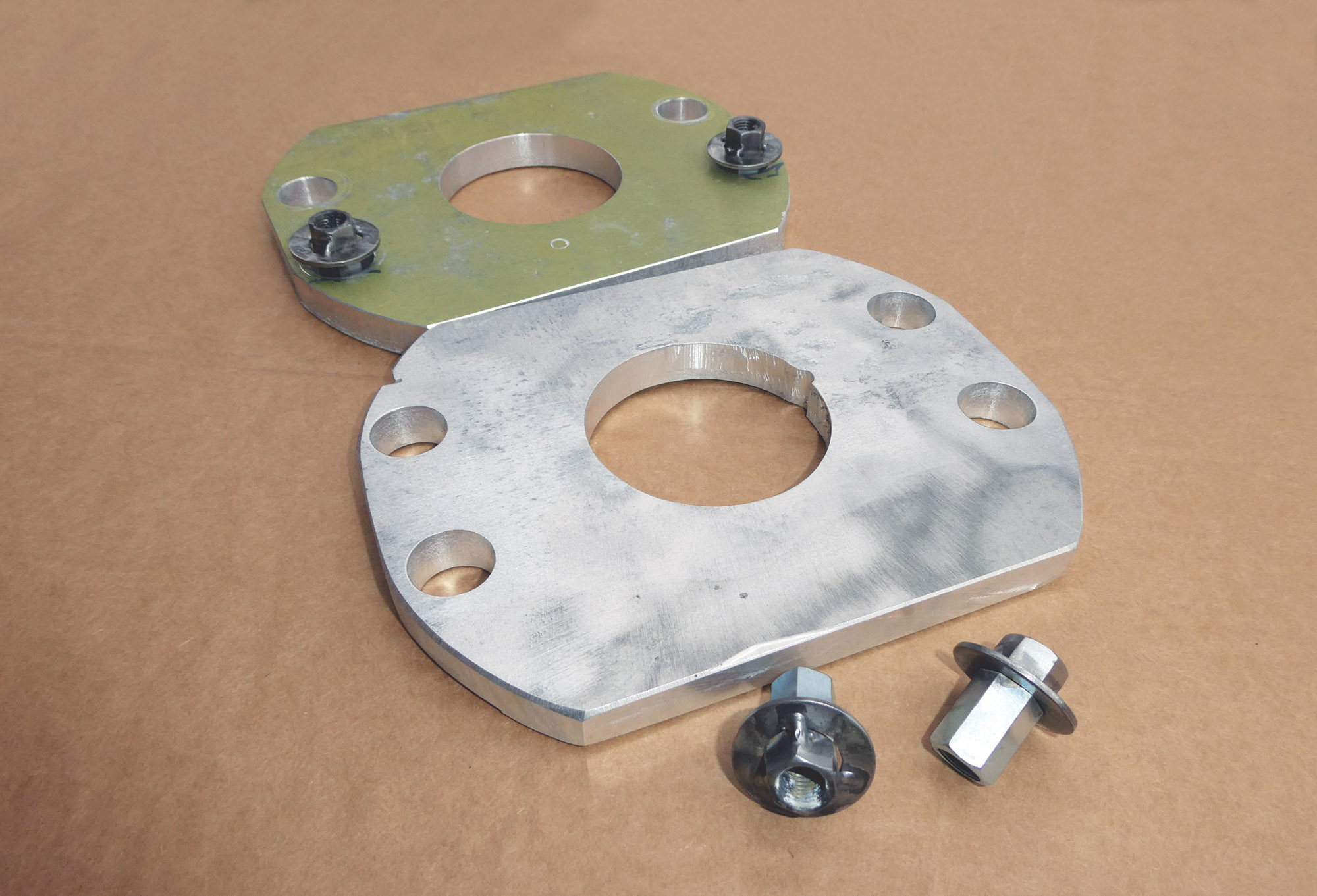
I had some 0.50-inch-thick aluminum plate on hand, which is a bit of overkill, but corrosion had rendered it unusable for anything else. Thinner plate, steel or aluminum, would likely have worked just as well. See Figure 1 for dimensions; you may need to adjust them for your particular engine. A fellow chapter member cut out the plates on a home milling machine, and another welded the washers to the coupler nuts (we have some handy guys at our Youth Build sessions). Both the washers and coupler nuts were sourced from the aviation aisle at a local hardware store. The 0.75-inch-diameter holes allow generous room for the coupler nuts and for the plates to tilt as necessary as the nuts are tightened.

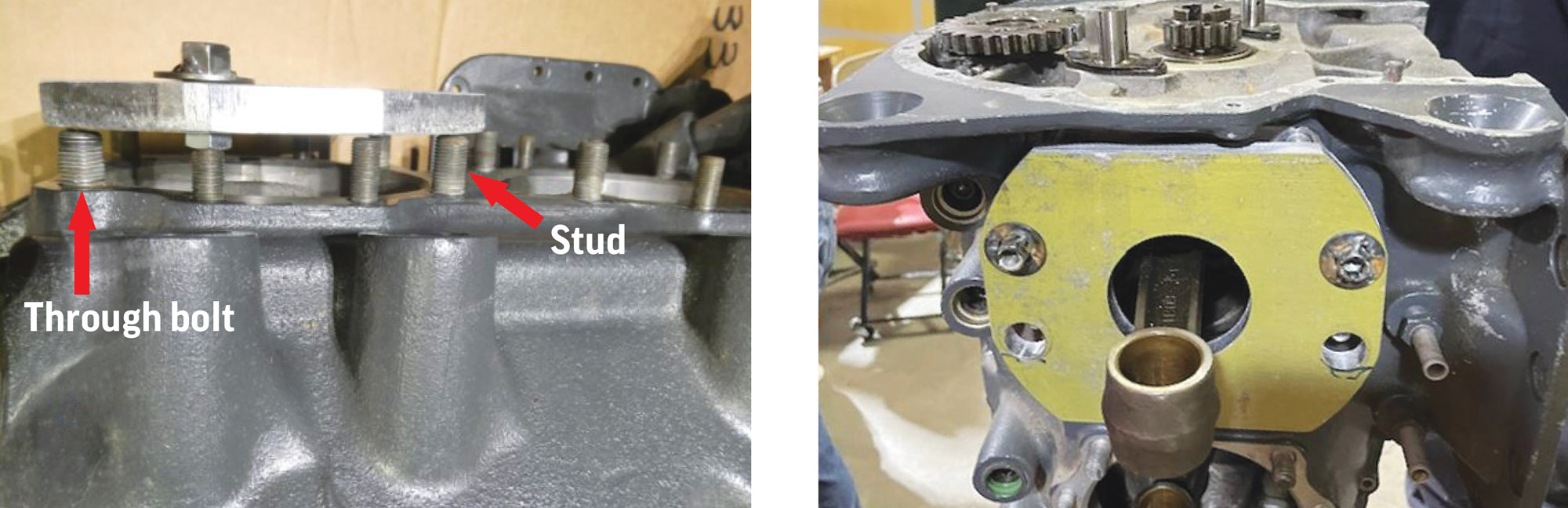
One plate is installed over the Number 1 cylinder, and the other over the Number 4 cylinder (Figure 3), with the coupler nuts located closer to the through-studs as shown in Figure 4. As the nuts are tightened, the plates are cantilevered off the big studs and press against the through-studs, forcing the case halves apart. Take it slowly and gradually tighten all nuts an equal number of turns. If the case isn’t parting evenly, stop and check to see if you’ve missed anything. In our case, we had removed the usual culprit—the bolt under the cam gear—but managed to miss one of the bolts on the bottom of the case.
It doesn’t take many turns of the nuts, and once the case halves are about 1/4 inch apart, they can be pulled apart by hand. Be sure to have extra hands ready if you are doing this with the engine mounted vertically on a stand—you don’t want a case half or the cam to fall to the floor.
In hindsight, we could have also drilled oversized holes where the large studs go, allowing the plates to double as torque plates if needed. If so constructed, place a thin strip of metal over the large stud holes to allow for cantilevering when used as separation plates.
Using scrap aluminum and a few dollars’ worth of hardware, total cost for the project was under $10. And now we part ways—until the next article.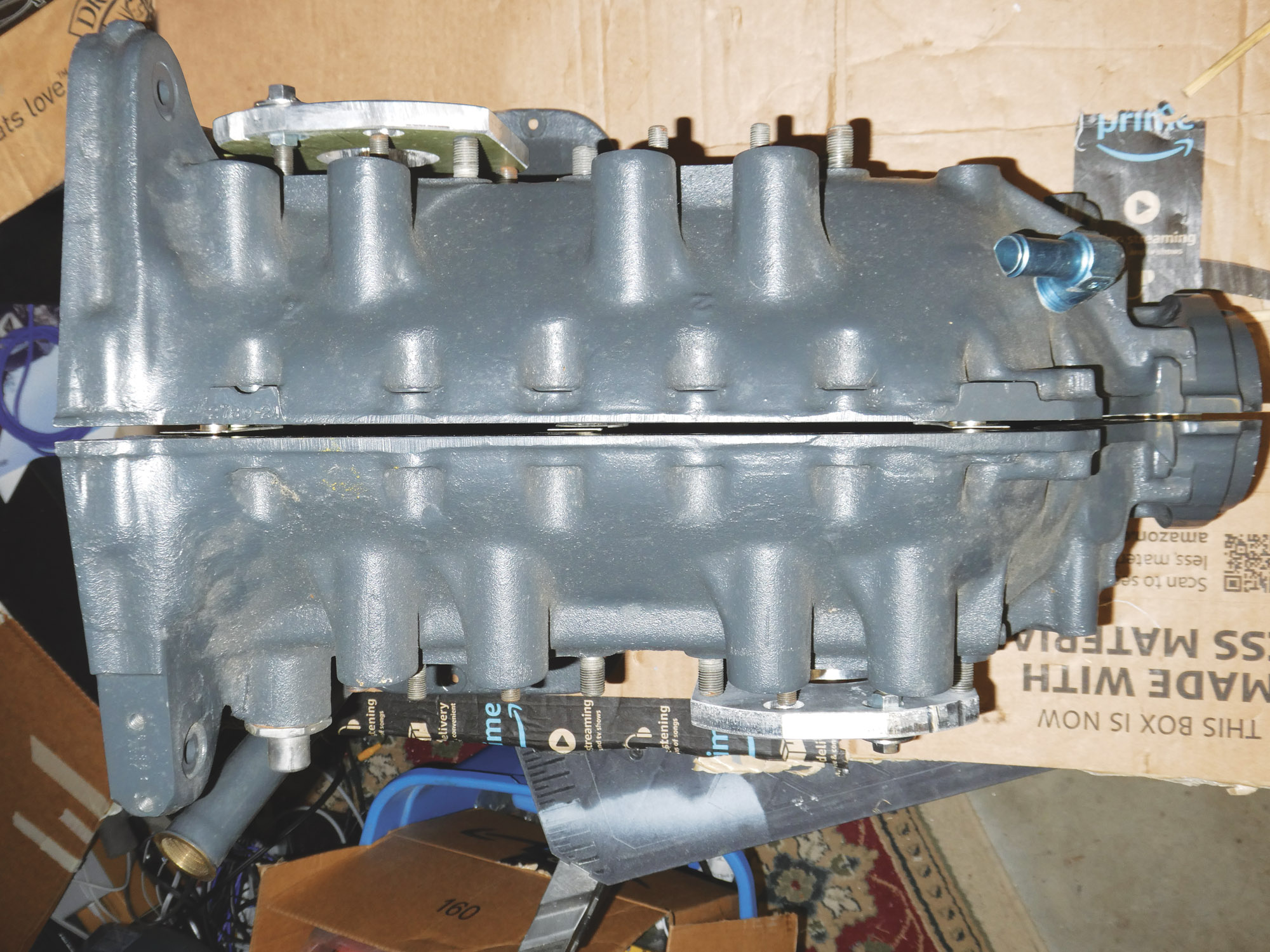
![[Credit: Lisa Turner]](https://www.kitplanes.com/wp-content/uploads/2026/02/Fuel-Selector.jpg?w=218&h=150&crop=1 "Fuel Follies")


