Bleeding hydraulic brakes of trapped air is something everyone who builds or works on airplanes eventually has to do. The process is fundamentally simple. But like most simple things, success is highly dependent on little details: using the correct hoses, having a good pump and reservoir, and since it almost always takes two people to bleed brakes, coordination and communication between partners. It seems like, no matter what, it’s always a bit messy. Beginners can expect some brake fluid to get on the floor or their shirt or pretty much over everything.
There is a lot of good information on brake bleeding procedures for aircraft, both on the DIY front and, of course, from brake manufacturers. The big difference between bleeding aircraft brakes (versus cars) is the use of pressure to purge the system from the caliper to the master cylinder. On a car, you pump the master cylinder with the brake pedal to push fluid out of the caliper. Why not do that on airplanes? On cars, there’s usually only about a foot in height difference between the calipers and the master cylinder, so any trapped air is more or less level with the brakes. Most aircraft tend to have long legs and brake lines that take a serpentine path to the master cylinder; you get the picture.
Not long ago, I was helping bleed the brakes on a new project and, as usual, it was a chore keeping the brake fluid from leaking all over. Ideally, the procedure should go like this:
1. Pump brake fluid into the bleeder hose to purge any air bubbles.
2. Push the bleeder hose over the nipple on the screw valve.
3. Pump about a half-stroke worth of pressure into your homemade or store-bought bleeder tank (see “Bleed Like a Pro!” by Jon Croke, November 2018).
4. Get the OK from your partner at the master cylinder to open the screw valve and, while making sure the hose doesn’t back off the nipple from the pressure, slowly open the bleeder valve. Once the fluid starts to flow, carefully pump another one or two times to keep pressure in the bleeder tank. Hopefully, that will be enough to purge the system of air.
5. When you get the second OK, close the screw valve, release the pressure on the bleeder tank and remove the hose. If everything goes according to plan, you’ll have purged all the air out of the brake line (at least for that caliper) and maybe only a little brake fluid spilled during the process.
Or, more likely, it goes like this:
1. Pump some brake fluid into the bleeder hose to purge any air bubbles. Brake fluid overflows and goes all over the caliper and tire.
2. Shut off the pressure and fetch a roll of paper towels. Better get two rolls.
3. With the bleeder hose purged again (this time more carefully), push the end over the nipple on the screw valve. Of course, we know from engineering class that fluids don’t compress (actually they do, but so little that we don’t consider it in most applications), so the fluid displaced has to go somewhere. Since it can’t go back in the pressure tank or in the caliper, it sprays out around the nipple like putting your thumb over a garden hose.
4. With the bleeder hose connected, pump about a half-stroke worth of pressure into the tank—which causes the now well-lubricated hose to start coming off the nipple. Pushing it back in place, you realize your hands are also soaked in brake fluid and made even more slippery because you’re wearing rubber gloves.
5. Calmly mention to your partner at the master cylinder that you’re ready to open the screw valve anytime now.
6. When you get the OK, slowly open the bleeder valve and once brake fluid starts to flow, hang on to that hose while simultaneously pumping another one or two strokes of pressure into the bleeder tank.
7. When you get the OK, close the screw valve, release the pressure on the bleeder tank and remove the hose. With any luck, no more brake fluid will spill out.
8. I almost forgot: Repeat for the other caliper.
You can guess which scenario went down for me.
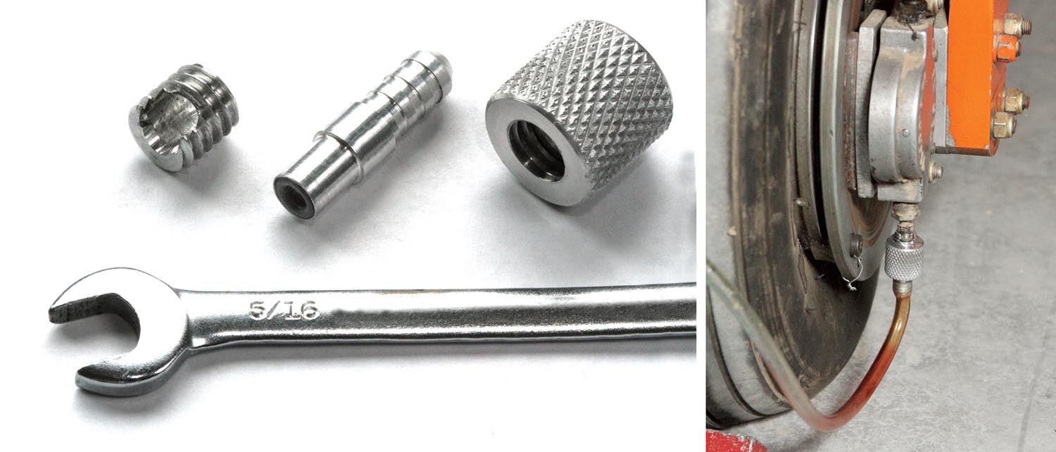
It’s pretty clear that the stubby nipple on the end of the screw valve is the main issue. It simply doesn’t have enough of a barbed end for a flexible plastic hose to get much grip. Commercial couplers exist to improve this issue, but they interface with threaded fittings designed to be used with commercial pressure tanks, like the spiffy ATS 225DX. While the ATS system is not that expensive, for occasional use it’s an investment most homebuilders seem reluctant to make.
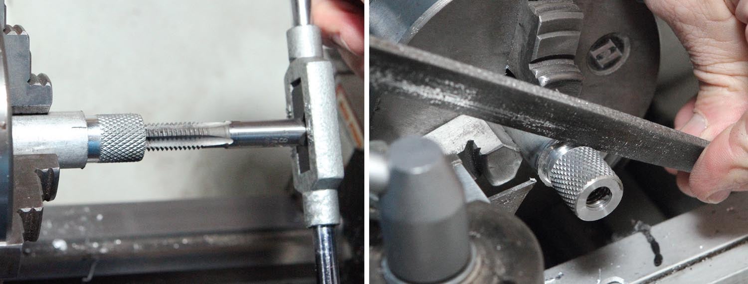
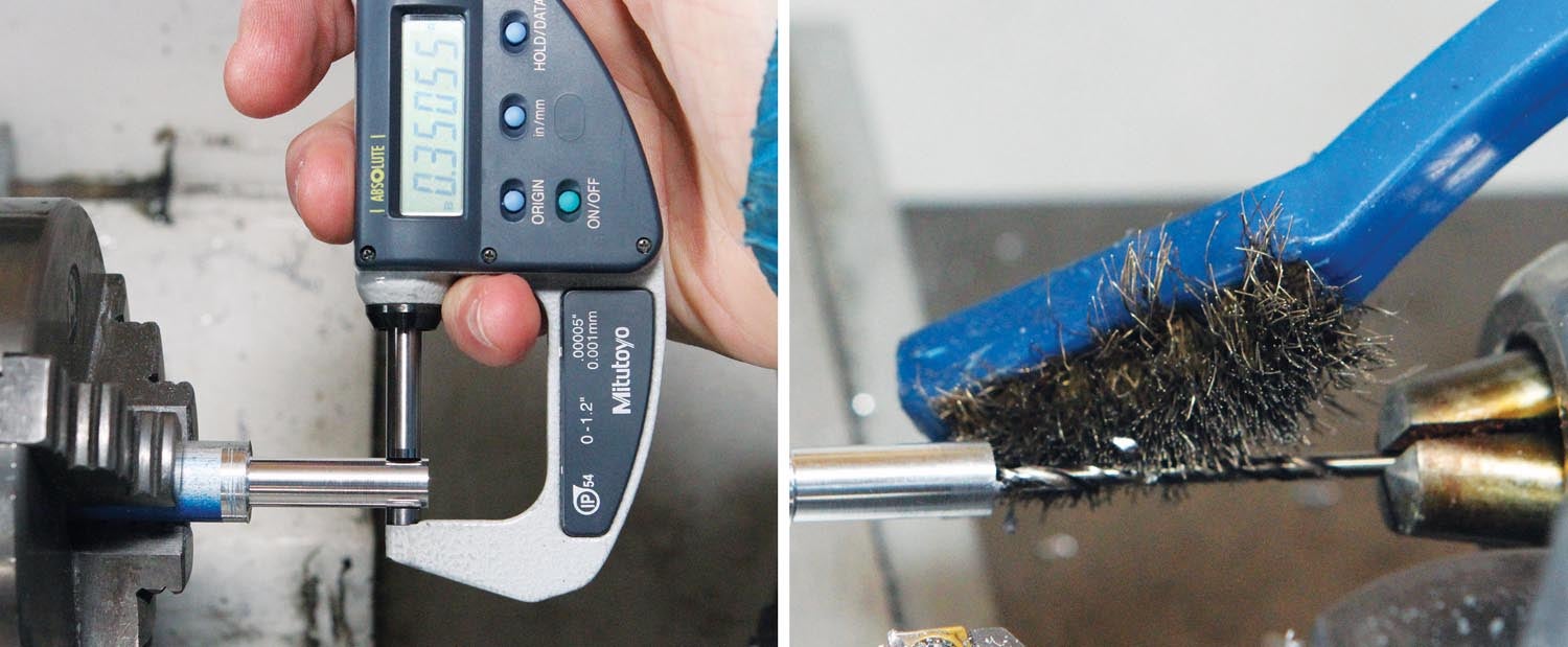
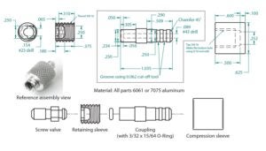
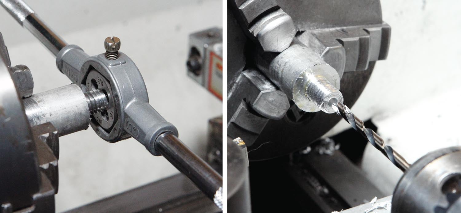
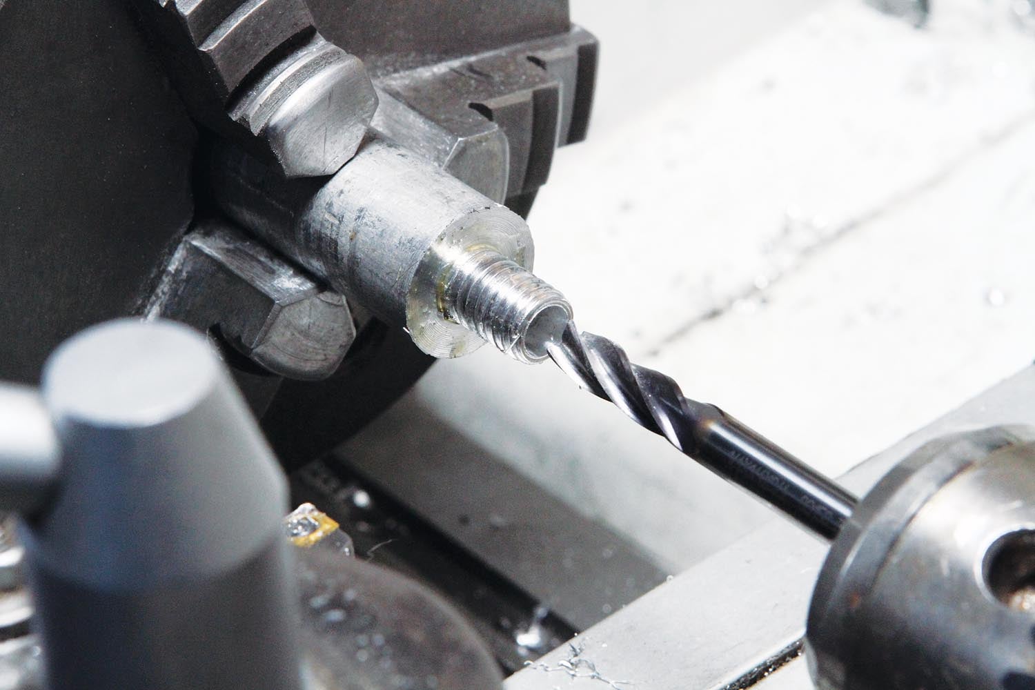
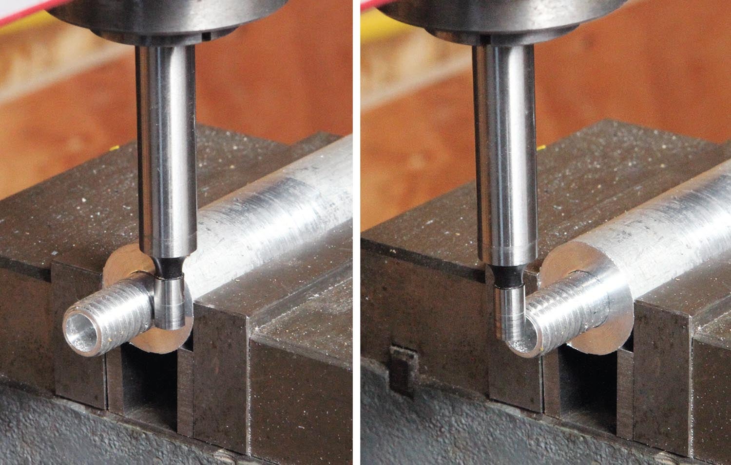
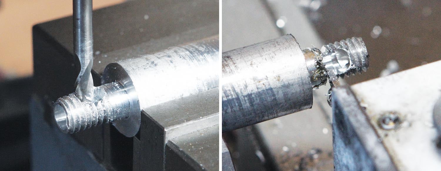
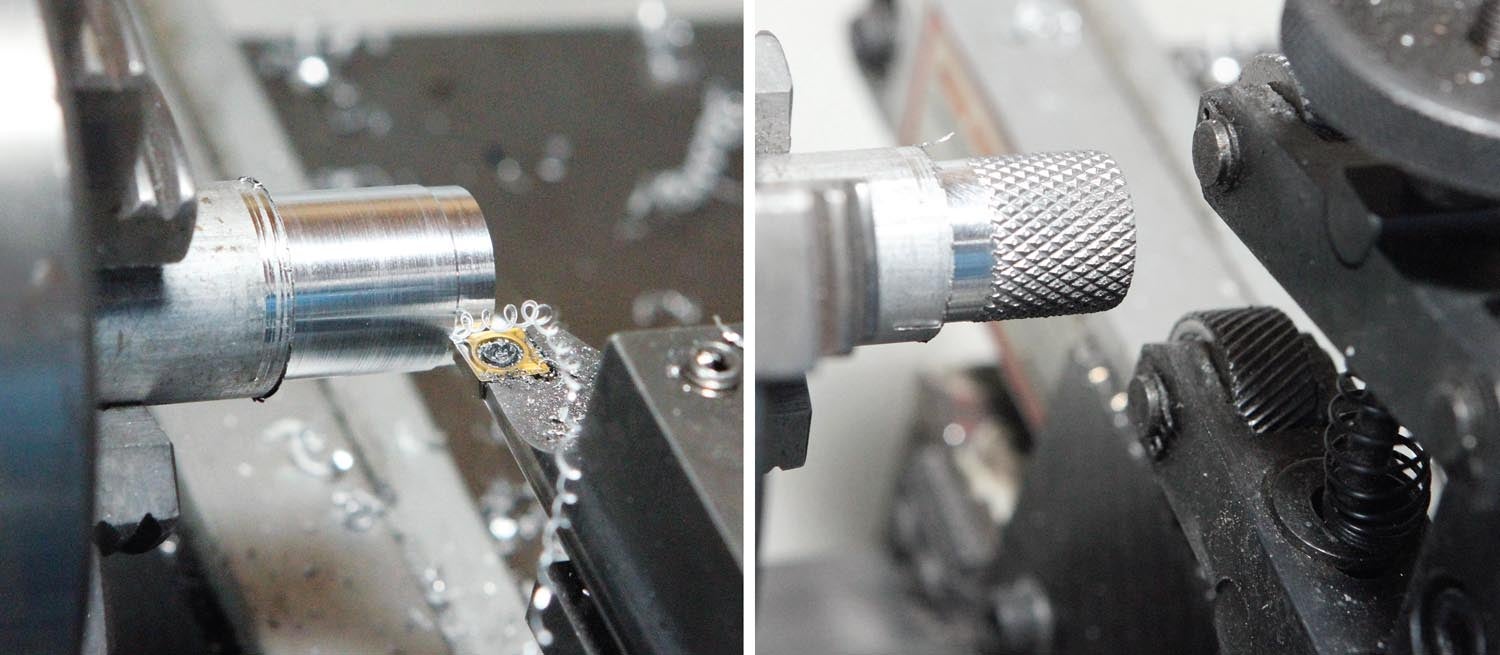
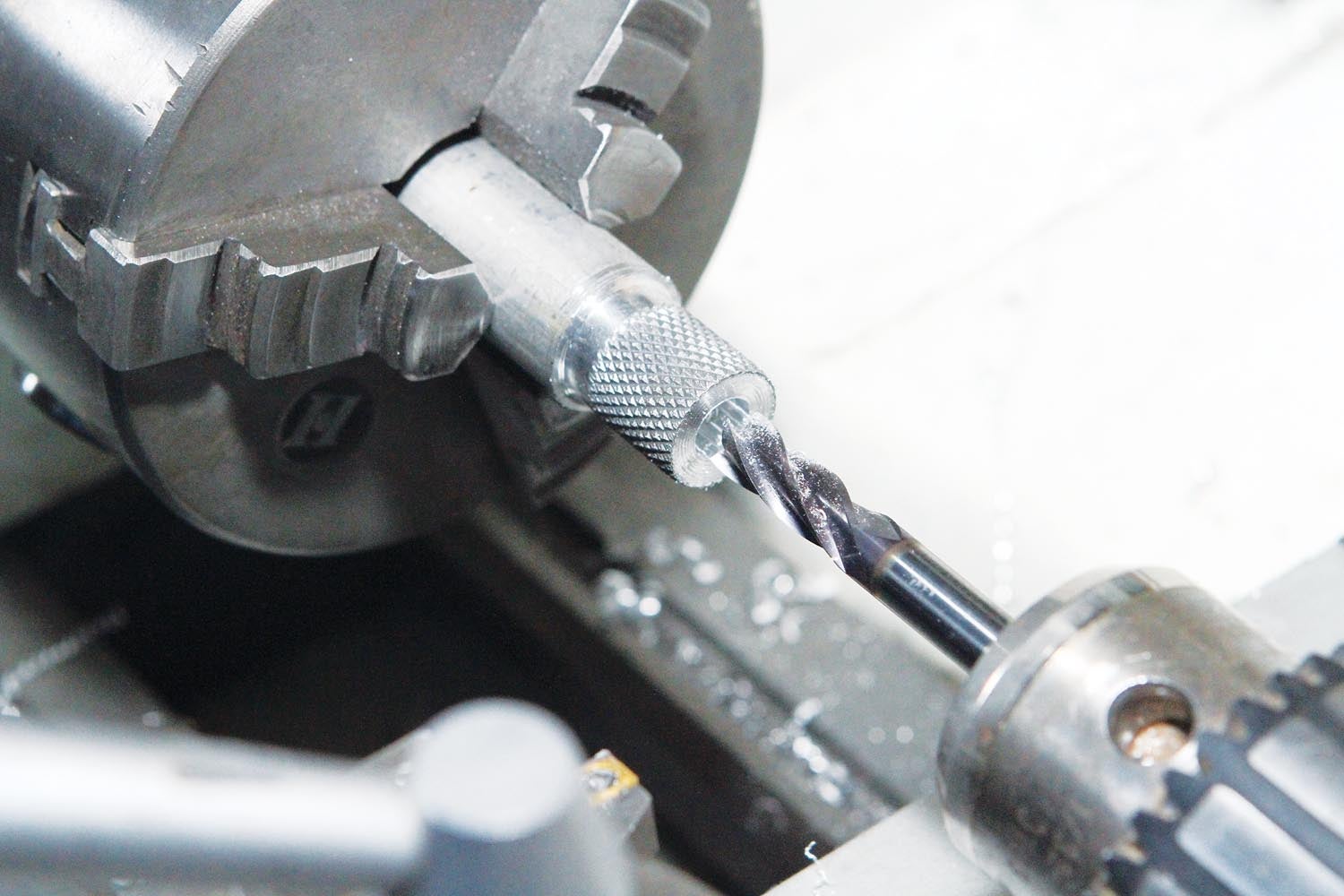
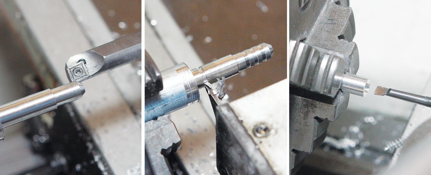
My recent experience got me thinking about a home shop solution. The result was a simple bleeder coupling that can be made in an afternoon with about 6 inches of 3/4-inch-diameter aluminum bar stock. To keep things simple, I used a small O-ring instead of relying on a metal-to-metal taper to make the seal, and it has a long hose barb with a 1/4-inch OD so you can easily hook it to whatever pressure system you have using a standard 1/4-inch ID poly hose.
That’s it for now, time to get back in the shop and make some chips!


This is one of the slickest tools I have seen … I have a pressurized Bleeder system from ATS and the coupling (which is now used by many others) leaves a lot to be desired (heavy hose connection, coupler does not turn with the bleeder, etc) … your solution is genius !!! … I wish I had the talent (and equipment) to make my own … with that being said can you make me one ? … I’m happy to pay … this is just such a wonderful tool I want one !!!
Thank you for your columns as I always look forward to what you are up to next …
Dusty
Thanks for the kind words. Unfortunately to assure compatibility my best suggestion is to see about having one made locally.
Are you a member of an EAA chapter? Most chapters have one or more machinist-types (often retired) that could look at the particulars of your brake system and (if necessary) adapt the design to work.
Bob
Comments are closed.