 We’re going to assume, for the purposes of this treatise, that you now have a workbench full of motorcycle drive parts sitting next to a mostly completed Xenos airframe. Perhaps you have a Xenos airframe with another engine already installed on it. If that is the case—remove that engine and then come back…we’ll wait!
OK, then: Ready to assemble? Installing the electric drive from the Zero motorcycle is actually a pretty simple task compared with building baffles, installing plumbing and wiring a conventional engine. So long as you have labeled the various electrical connectors when you took the bike apart, hooking things back up is fairly easy and bolting the boxes in place is a straightforward task.
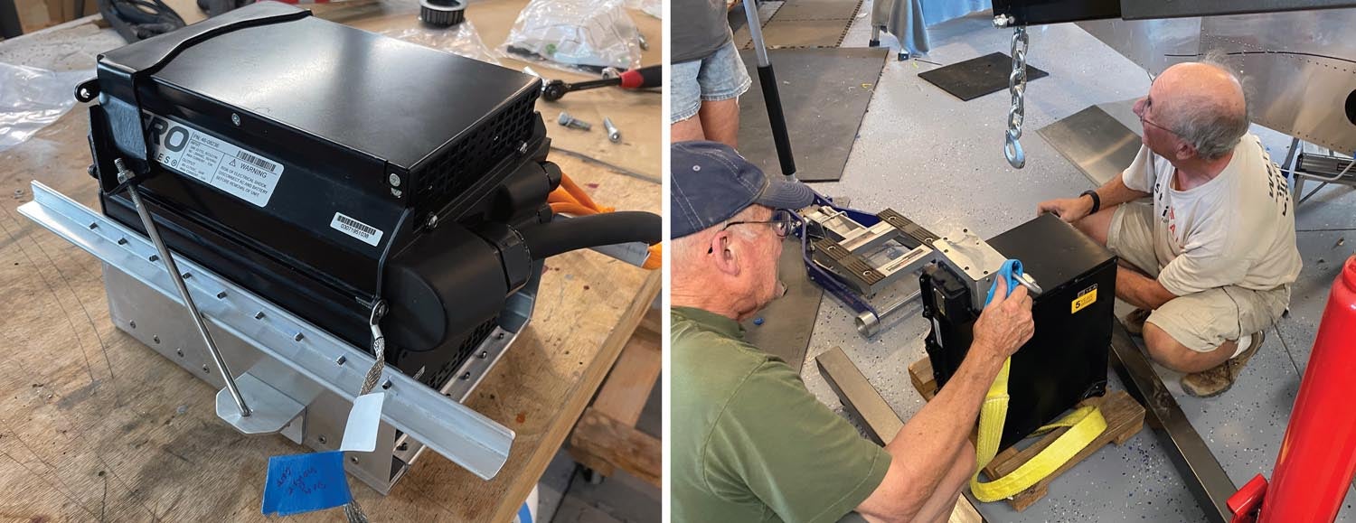
Mounting the Battery
The “motor mount,” which I tell folks should really be called a battery mount, supplied by Sonex for our project was designed perfectly to hold the 180-pound battery box parallel to and about an inch in front of the firewall. The inclined firewall on the Xenos presented a challenge when it came to actually installing the battery, however; the battery mounts to four points (with four bolts) at the four lower corners of the box. While it could be lowered into the frame of the motor mount from the top (once you had removed the firewall box that houses the original design’s fuel filler), this would only really work well if the battery was going in vertically. But since it has to go down and back, it would require some muscle to move it into position while lowering. And the two rear bolts were going to have to be put in through the firewall—requiring punched holes and closeout plates. Picturing the tug of war between the battery and gravity—while trying to get it into alignment and put the four bolts in—prompted an evaluation and a search for an easier way.
That easier way was to hang the battery from the engine hoist in the middle of the shop and move the motor mount to it! This was made even easier by the fact that the gear legs, axles and wheels were already attached. We could then roll the motor mount into position. With a couple of helpers, it was a simple job to hoist the battery slightly above the final position, then put the motor mount where we needed it and lower the battery into its slot. The four bolts slid right into place since we had previously measured and drilled the necessary holes (measure four times, drill once). With the battery bolted into place, we rolled the assembly back into position on the firewall—the fuselage being supported on a work stand—and Clecoed it into position. We then replaced the Clecoes one by one with the final bolts and the battery was mounted!
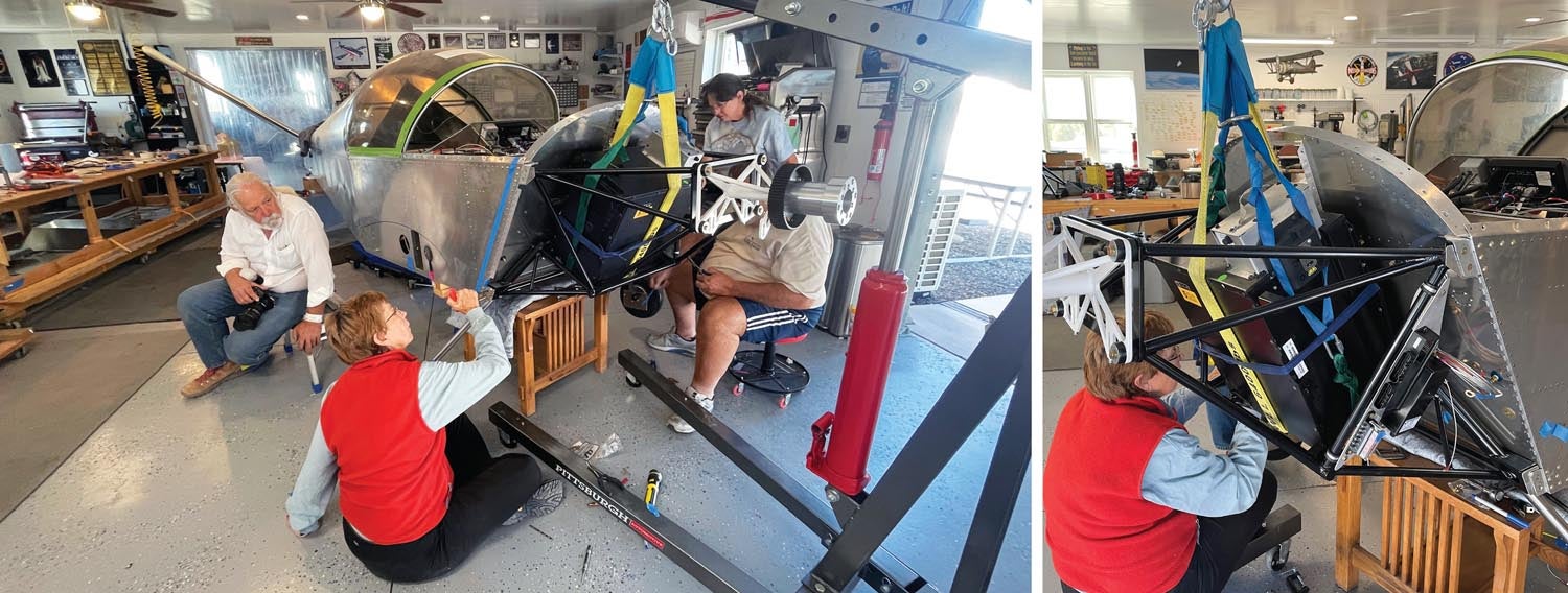
Finding Spots for Everything Else
Before we start finding spots to mount the rest of the power system, I should admit that before we had decided how to mount the battery, we had removed the “doghouse” that would normally contain the fuel tank filler forward of the plane of the firewall. It was riveted in place long ago, but was going to be in the way if we lowered the battery in place, so we drilled out the two dozen or so rivets and removed it. You’ll probably need to do this as well—even using our mounting method—because you are going to need to figure out how to run some cabling through it.
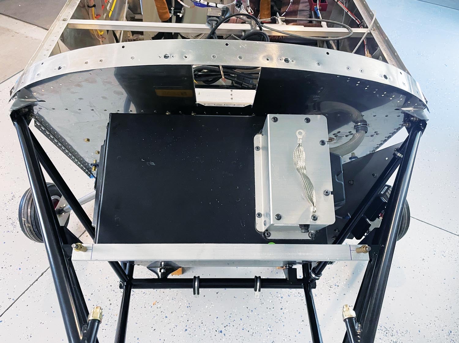
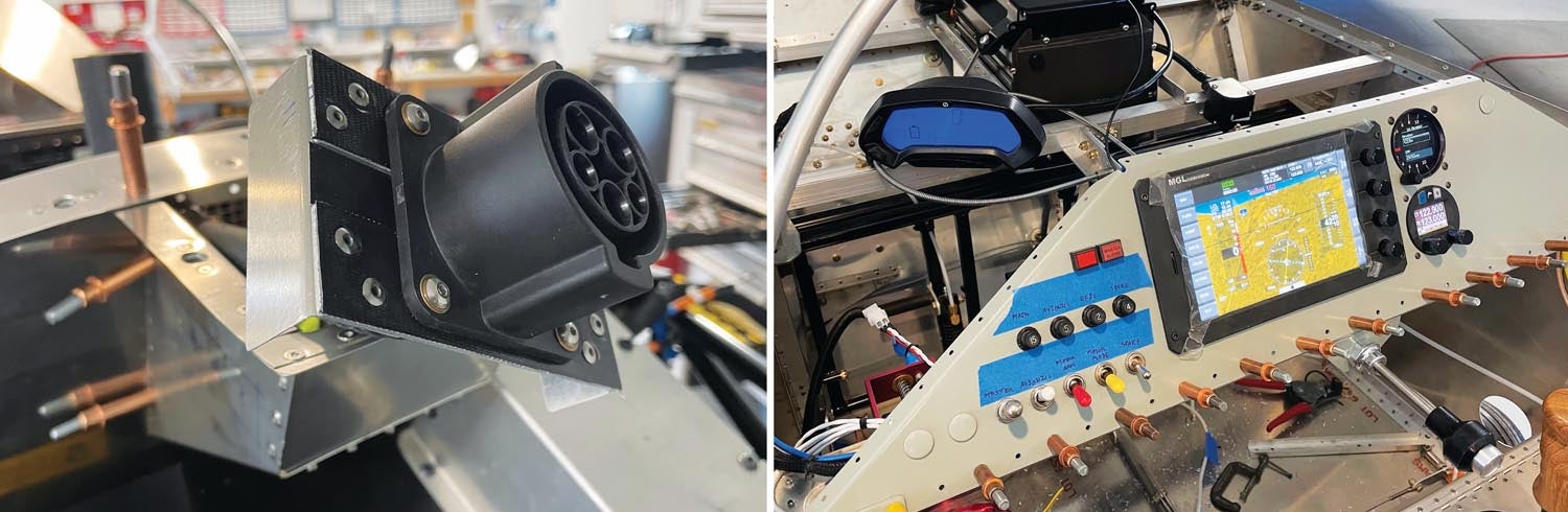
The major FWF components of the power system—other than the battery—include the motor, reduction drive, motor controller, Main Bike Board (computer), DC/DC converter and the 12-volt fuse block. Frankly, the fuse block can easily be replaced with a single “main’’ circuit breaker on the panel, but it’s part of the bike circuit and easy to reuse.
The location of the motor is pretty obvious (it goes on the front) and the only other thing that has a certain criticality as to location is the motor controller. This heavy black box with big electrical contact lugs on it is made heavier with a finned heat sink, which should tell you that it needs to have some airflow over it. In Gabe DeVault’s design, it is mounted behind and slightly below the motor, sloping down toward the bottom front of the battery. This allows cooling air to flow through the fins on the way out the bottom of the cowl.
The MBB and DC/DC converter are easily mounted to an accessory plate, which we made out of 0.060 aluminum and Gabe made out of a piece of carbon fiber plate (very trick) that he had around. The plate is Adel-clamped to the motor mount on the left side. The fuse block joined the two black boxes on the plate because that is where it fit.
The most important thing—after cooling—for mounting all the components is to put them where the cabling will reach. While you can lengthen harness wires if needed, it is really nice to not have to do that. You are unlikely to have all of the tools necessary to work with the many different connector types in the harness and lengthening wires between connectors involves lots of joints, any one of which can introduce a potential failure. We were able to put the entire package together while only lengthening two major wires—the battery charger cables—and a small assortment of switch wires that had to reach back to the panel. Nothing in the major “cluster” firewall forward had to be touched.
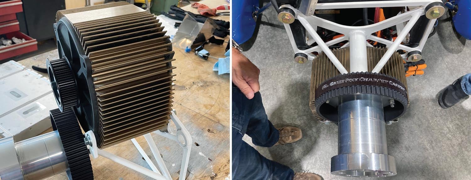
Motor and Re-drive
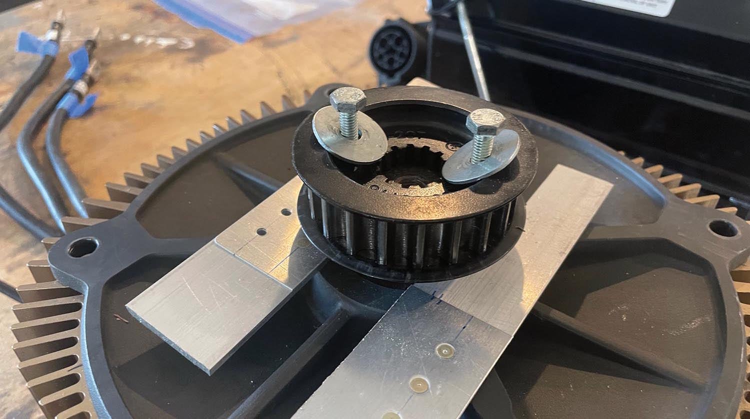
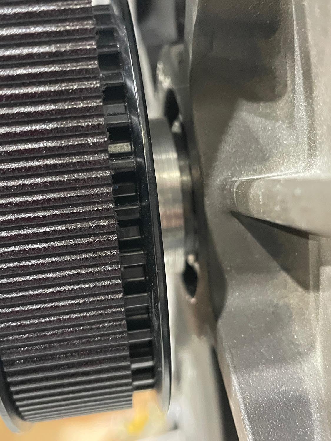
Mounting the prop-reduction drive (re-drive) is simple and has no options—it is supplied with rubber mounts and fits where intended on the big motor mount. The bike’s electric motor fits underneath the output shaft and hangs on four metric bolts, which thread into the motor housing itself. They aren’t part of the re-drive kit but are easily obtained from the usual hardware sources. The re-drive has adjusting screws for each of the four bolts—ingenious little screws (with locknuts) that allow you to fine-tune belt tension. It does take a little fiddling to make sure that you not only have the belt tension correct, but that the shaft of the motor is almost parallel to the output shaft. You actually want them very, very slightly convergent so that the belt will not run off the back end of the driven pulley. This is a place to take your time and get it right!
The re-drive itself is very simple. The bearings ride on the central shaft and support the output wheel, which mounts the driven pulley in back. On the front, you bolt the prop flange—this can be designed to fit any prop, of course, but in our case it is set up with six holes on a 4-inch circle—standard for the size prop you use on a Xenos. There is no easy way to provide for safety-wiring the prop bolts, especially if you use the machined bullet spinner from Sonex. But Nord-Lock washers do a great job of keeping the bolts from loosening and are approved in numerous prop bolt installations, even on certified aircraft.
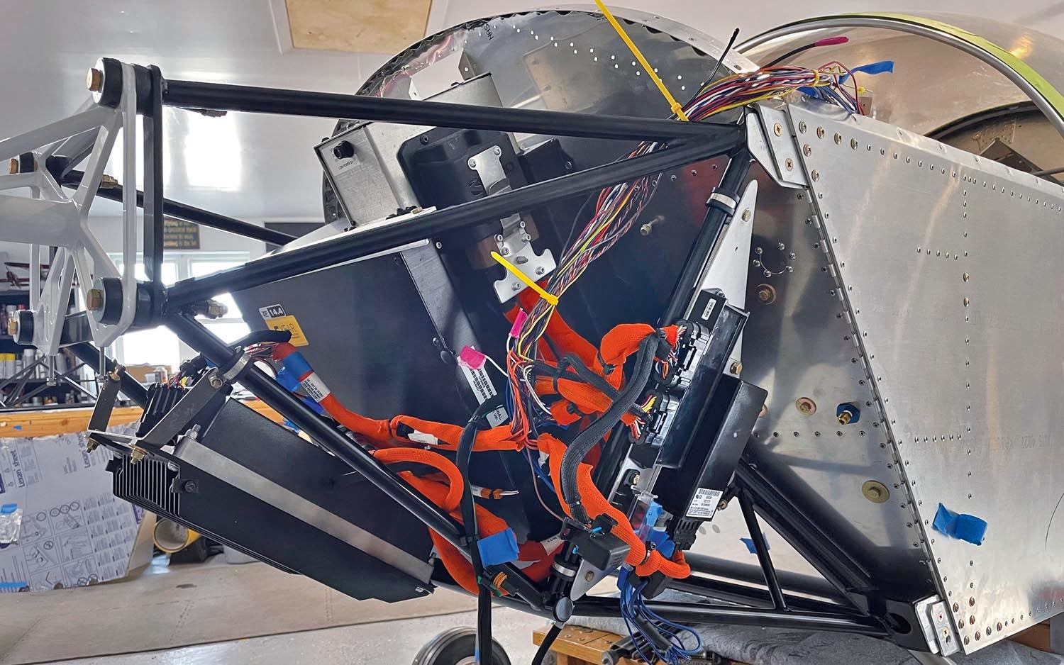
Wiring and Cabling
When you take the bike apart and strip out most of the 12-volt wiring you’ll find that you have a lot of wire bundling material sitting about. The harness uses two colors—orange and black. Orange is mostly for the high-voltage, high-current bundles while black covers the low-voltage stuff. Hopefully, you didn’t throw any of it away because it is reusable and split so that you can install it over a finished bundle. This stuff is your friend because it really helps to straighten things up after you have routed the wires and cables where they need to go.
As with any wiring job, start with the big stuff first and start at a central point. In this case, that means the connectors to the MBB. These two connectors are about 6 to 9 inches from a major nexus in the wiring harness and this will end up right below the main connector to the battery. This main connector needs to be put in place pretty early as well, but don’t actually connect it and leave it that way or you will have hot wires connected directly to the battery posts any time it is plugged in! Safety first: Connect it only when you have to in order to make sure the wire runs work.
Next up, route the big cables to the motor controller—you’ll have three that go to the motor and two that come from the battery. Don’t tighten anything up because you’ll be adding a few things later. Frankly, just hook everything up, using the labels you taped on when you took the bike apart (you did do that, didn’t you?), and see how it all shakes out.
With all the big cables in place, you’ll have some mystery connectors—they are charging cables for the standard bike battery charger (which you’re not using) and some connectors for auxiliary chargers. Bundle them up and put them out of the way—you can do a final secure on them later.
Next, you’ll have a bundle of wires that need to go to the panel—pairs of wires from the master switch, motor “arm” and mode switches. You’ll also have the bundle of wires that goes to the display—and you’ll have a set of 12-volt positive and negative wires coming from the fuse box that need to go to the panel for anything that is part of the airframe wiring.
Lastly, you’re going to have to connect the big battery charger that mounts behind the firewall, above your legs. The control wires are sufficiently long that they will reach but the two large #8 output wires will need to be lengthened to reach their connections on the motor controller. Some wire, #8 crimps and a little heat shrink do the trick.
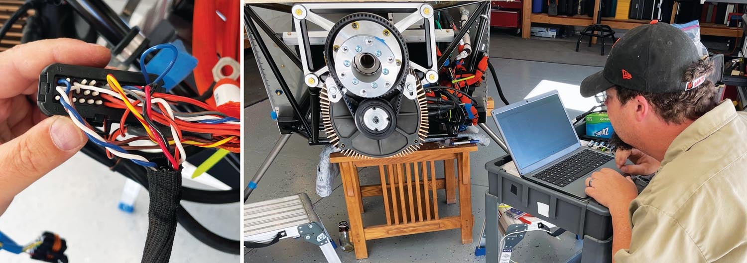
A Little Programming
With all the connections made and boxes installed, the hardware work is done—but there is the small matter of software. And this can be tricky, at least in this early stage of using the Zero power package. Programming requires a special cable connection and some software in a laptop that Gabe has and knows how to operate. But Gabe’s programmer is the only one in captivity outside of the Zero dealer network, so it’s important that he is dedicated to helping people get these powerplants into airplanes!
The programming consists of a couple of steps—telling the power package that it is no longer in a bike and getting the direction of rotation right. This is followed by a calibration routine to match the new throttle controller to the system.
If you happen to have a prop that turns in the conventional direction—clockwise when viewed from the pilot’s seat—you have nothing to worry about because the motor is already set to turn that way. But Sonex aircraft designed to work with the AeroVee have props that turn in the opposite direction because, well, that’s what the Volkswagen does. You can buy props that work in either direction but if you already have a prop designed for the AeroVee (like we did), then you need to change the motor’s direction of rotation.
I said that we were done with hardware, but I guess I lied a little. At least this bit of hardware work is trivial—changing any two of the three motor connections to the controller. Pick whichever two give you the neatest wire bundle. In our case, that was swapping wires B and C. With that done, the motor is going to turn counterclockwise.
Back to programming. The bike has some sensors whose inputs need to be spoofed. One is the kickstand switch—the bike is designed so that you can’t energize the motor if the kickstand is down. But this switch is no longer part of the package—so you go into the software and set the “kickstand up” bit permanently. You have to do the same thing with a “crash detection” switch, which is actually internal to the computer—it’s a G sensor that won’t let the bike energize if it is not upright. Now the motor will power up.
Gabe ran a calibration routine and then we added just a touch of throttle—and the thing came to life. It is actually a bit odd to be powering up an airplane motor—especially with a prop mounted on it—inside the shop. You just don’t generally do that with an internal combustion engine! But with electric, make sure the wheels are chocked and keep the prop arc clear, then run it as slowly as you can. Now go out and celebrate—you have created an electric airplane power plant!
Next time, we’ll cover all of the little mechanical bits that had to be taken care of to efficiently and safely mount the powerplant—for now, just sit back and watch the electrons spin the propeller.
Photos: Tom Wilson and Paul Dye.


