KITPLANES Magazine, September 1997
Building a RotorWay 162F
Part 7 of 8: We finish the new helicopter.
by Jeff Dunham
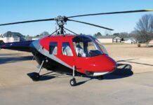
It’s been seven short months and our RotorWay 162F kit helicopter is just about finished and ready to fly. Last time we completed almost everything that could be done in the garage, so now we’re about to head to the airport.
The Hurdle
But first we have to hurdle a major obstacle that’s been bugging me since Day One of construction: We have to get this thing out of my garage! W
What’s the problem? The ship is tall and the garage door is short. I’ve built the proverbial boat in the basement! But Tom Smith at RotorWay has assured me all along that they have dealt with this same problem a couple of times when crating fully built company ships that had to travel overseas to their demo destinations.
He said the shipping crates could only be a certain height and length, so they had to compress the 162F down to acceptable dimensions. To cut the length, the tailboom detaches from the main frame with only eight bolts and it can be removed fairly easily, as can the accompanying tailrotor drive belts and the pitch control cable.
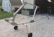
As for the ship’s height, instead of wrestling with the complications of yanking out the main shaft and literally tearing the ship apart, the alternative is to remove the rear landing gear and lower the back of the main body almost to the ground so the ship can sit in a nose-up wheelie position. This will of course reduce the height profile of the ship significantly. That sounded pretty easy to me, and I thought if we could pull it off, it would be nice to say that you truly can build a RotorWay Exec 162F in your garage…And get it out!
So how tough was the procedure?
It was a pain in the rear. The house I currently live in has an old, really short garage door, apparently shorter than the required height of an overseas shipping crate! Removing the giant wooden double garage door was an alternative, but that didn’t look like too much fun either. Once you understand the anatomy of a RotorWay ship, numerous solutions to our problem could be concocted, but I opted for the method Tom described.
We put a floor jack with wood blocks under the ship at the lower engine mount and picked the rear end up just enough to get the rear landing gear off the ground, similar to installing the engine. After unbolting and rotating the rear landing gear out of the way, we lowered the back of the ship as far down as the jack would go. Then, as Tom said they did at RotorWay, I would simply have to roll the jack and drag the heli a few feet to freedom!
Guess what? With the floor jack completely collapsed, the ship was still a couple of inches too tall! I could have sworn I measured the garage door months ago and it was the 6-foot height Tom said it needed to be. But nope…With the door open, the clearance was barely 5 foot 10. Maybe one of our recent little California earthquakes shrank the opening. So to get this ship out of the garage it needed to go lower…a lot lower.
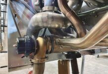
The ship’s exhaust system would literally have to be scraping the ground for clearance. So we would have to remove the muffler as well as the floor jack! Well, you can’t rest the ship on the ground in the rear with no other support because this would crush the fan shroud and radiator. So with three of us standing there scratching our heads, looking for ideas and searching around a pretty barren garage, we devised a method of suspending the rear of the ship’s frame from a hand truck (dolly).
We had to get the height exactly right, avoiding crushing any heli parts and still allowing for garage door clearance. Keep in mind that we were dealing with about 600 pounds of dead weight here. Any slip-ups, and I’d be doing repair work for a good while. And we were also trying not to kill ourselves in the process.
About 3 hours into this mess, the ship was barely low enough to slip under the garage door, and only if one of us pushed up on the door! Even though the rear of the ship was now suspended by the dolly and thus could roll, the front of the ship was still resting on the aluminum skids.
With a typical older Southern California garage and driveway, we were getting ready to drag this monster over cracked cement and numerous dips and joggles in the asphalt topography. It was obvious that pulling and scraping this much dead weight over rough terrain was too much for mere mortal strength. We needed power. I fired up the Hummer.
Free at Last
In retrospect, I guess it was overkill using a 12,000-pound winch from the front of a military vehicle to drag a few hundred pounds out of a garage. But it makes for a good story. Once we got the height thing right, one flick of the Hummer’s winch switch and the 162F was out in the open. We left a little aluminum from the skids embedded in the driveway, but at least the ship was free!
In the driveway, after reassembling the landing gear and muffler, I put most of the body panels and windscreen back on the copter. In article No. 3, (May, ’97 KITPLANES), we trimmed and fit the body panels and windscreen, and we installed all required nut plates and Dzus fasteners, so all I had to do now was assemble all the sections with screws.
To the Airport!
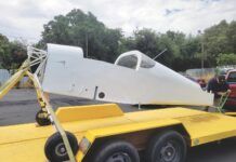
About 10 years ago I had a 30-foot flatbed trailer built for hauling my original Exec around the country, so I brought it to the house and loaded the boomless ship. As you can see in the picture, I also have a small landing pad on the trailer that makes loading the ships a lot easier. You just land on the trailer, pull the blades off the ship (a 10-minute procedure), bolt the skids to the trailer, support the tailboom, and off you go. To get the new 162F on the trailer, however, since it couldn’t fly yet, we used ramps and rolled her up to the platform. (The Hummer winch came to the rescue once again.)
Details
Finally out at the hangar in Camarillo, I finished a few details before mounting the tailboom. One thing I forgot to mention in the last issue regarding wiring the ship and gauges was an oil pressure electrical switch. This is a switch that mounts to the back of the oil pressure gauge and will close an electrical connection only when there’s oil pressure. Your Hobbs meter wire runs through this switch. Why?
Without it, whenever you turn on the electrical system in the heli, the Hobbs meter will run even though the engine is not turning. This is wasted time on the meter, which will cause you to replace falsely timed-out parts.
Nifty Updates
A 162F update that came out since the beginning of this series was two new fiberglass air scoops that mount in the belly of the ship.
According to RotorWay, this added airflow reduces engine temperature significantly. If what RW says is true, I would highly suggest adding these to your aircraft. The new scoops are an option, and older models can be retrofitted.
Another item pictured and new to the 162F is a simple aluminum pipe mounted aft of the seatback. It pulls the fore/aft control cables forward and off the oil bath cover’s edge. This is a neat little fix. In earlier models, the cables, as smooth as they are, would rub against the oil bath cover and chafe some pretty significant grooves into the thing. I used to glue a thin piece of rubber on the front of the bath, but this new pipe also keeps the cables out of the way of a few other items down lower.
Things that Stick Out
Next I mounted the T clutch handle. It’s simply a steel rod that is located between the seats in the passenger cabin at about neck level, and it runs rearward to the aluminum actuator arm of the idler pulley assembly.
As we’ve described before, the idler pulley simply tensions the belts to flying specs after engine startup. This handle comes welded from the factory and all the builder has to do is cut it to exact length, tap threads for a rod end, and bolt it into place after running it through a hole and rubber grommet in the seatback. You can paint the handle or have it chromed.
This point in construction is a good time to install any antennas you’ll be using. I mounted the small blade-shape transponder antenna in the belly of the ship, using a 0.025-inch aluminum plate pop-riveted inside the fiberglass. This 9×9-inch plate functions as a ground plane (run a wire to the ground) and beefs up the mounting surface as well. As for a com antenna, I’ve found the best place to mount it is somewhere on the underside of the tailboom. This puts it away from the transponder and out in the open for good reception and transmission, and it keeps it away from a lot of RF noise created by spinning parts. We’ll get to the tailboom mounting a little later.
Another detail we haven’t covered is the fuel cut-off handle. The construction manual calls for the handle to be installed in the floorpan, in the middle of the flat portion of the fiberglass between the cyclic panels and just in front of the passenger collective. Homer Bell pointed out to me that this wasn’t an optimum location when you consider taking the ship apart. A better idea is to mount the handle into an oblong hole that you can cut into the side of one of the cyclic inspection panels. Then the handle assembly can simply be loosened and slid out of the hole if the floorpan needs to come out. Otherwise you’d have to detach the cable way back at the engine behind the seat and pull the whole cable back out through its hole. This is no fun considering that the attachment point of the cable is in the engine compartment at the fuel cutoff valve, hidden behind and below a lot of other components.
Cockpit Amenities
Next I installed the seat cushions. This is a no-brainer and requires only a few nut plates and a few pieces of steel flat stock. I have no amazing tips here; I just followed the instructions. After you get these installed, however, this is where a family member will probably catch you at midnight: You’re sitting in the helicopter seat making engine noises.
Boom Time
The 162F tailboom is an aluminum semi-monocoque structure consisting of four cast aluminum bulkheads, six aluminum stringers that run the boom’s length, and one giant piece of 0.025 aluminum skin. The boom comes fully formed from RotorWay, ready to be prepped and painted. All the builder does is fabricate the inspection covers and drill a few holes. Other than that, it’s just another bolt-on item…which really ticks me off!
Back in the earlier days of RotorWay, we had to build our tailbooms!
Receiving it already finished and ready to go is cheating! But this certainly saves the builder a heck of a lot of time. Gone are the days of constructing your own saw-horse jig, measuring to the millimeter every angle and length, rolling the skin, laying out, drilling and deburring hundreds of rivet holes. Humph….
The mounting of the boom is pretty critical and shouldn’t be rushed. It’s a stout structure, but any nicks, dents or even scratches should certainly be avoided at all costs. A scratch in the skin shouldn’t be just painted over, either. With the high-frequency vibrations from the tailrotor that the boom is subjected to, any scratch is a candidate for an eventual crack. Sand the aluminum smooth if you get any significant scratches! And if you get a dent, call yourself an idiot and contact the factory. They’ll make their own judgment as to what you should do.
Use accurate bubble levels and a high quality protractor level to go through the boom mounting procedure. And I mean a good protractor level–not a plastic one with a hanging angle indicator. Go to a tool supply house and get one of the metal kind that uses a bubble for measurement. Angles are very critical here, and you’ll use this instrument when mounting the main blades as well. Don’t skimp on tool quality at this point. You’ll also be using a plumb for the boom, so try to mount the boom with the helicopter sitting on a level, flat floor.
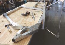
There are only four attachment points for the boom to the frame, and when most people see how it’s held on, they wonder why it doesn’t break off in flight. Four heat-treated steel brackets telescope into the airframe, and the builder must slide the boom within these brackets and adjust the brackets and boom into all the correct locations and angles. Two quarter-inch holes each are drilled into the flat part of the mounting brackets and into ears inside the boom. These ears are part of the forwardmost and largest of the cast aluminum bulkheads. The instructions are good regarding lining up the boom once it’s within the bracketry, but they are lacking when it comes to actually getting the boom within the brackets!
This is a tough procedure for first-timers because the brackets are very tight around the boom and it seems that it won’t go together. The easiest procedure is to pull the bottom brackets out as far as they will go without falling out of the frame, while pushing the top brackets all the way into the frame. You then raise the boom to a much greater angle then it will actually be mounted. I set the bottom edge of the boom on top of the lower brackets, then pushed and slid the boom into place, slowly lowering it to the correct angle.
I used a plastic hammer to tap the lower brackets into place, and the two upper ones back out a bit. The boom must of course be supported this entire time; it can hang free only after all the bolts are in place in the boom as well as in the telescoping brackets. Two 316-inch bolts each go through the airframe and telescoping brackets.
Flying Surfaces
Next we mount the horizontal stabilizer to the tailboom.
As the stabs are already riveted to their spars, the builder simply mounts them to the boom. The angle of the horizontal stabilizer is critical in regard to flight characteristics and must be to exact specs.
Even a degree or two off will alter where your fore and aft cyclic ends up in forward flight. We need to take our time and use good tools!
Fiberglass winglets must now be attached to the horizontal stabilizers. This is one of only two places in the entire kit where the builder must do any glass work.
Tailrotor Prep
The builder must now construct the slider rails for mounting the tailrotor assembly. Since the 162F uses belts for power, there obviously has to be a way to tighten the belts, and that’s what this structure is for.
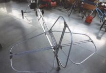
The tailrotor is powered by a series of three V belts that spin inside the tailboom, supported by two sets of free-swinging pulleys. The first tail belt comes off a pulley located on the bottom of the secondary drive unit, mounted just above the fan shroud and fan. This belt then runs to the first set of pulleys located about a third of the way down the tailboom. The second belts runs to the second set of pulleys, and of course the last belt goes from there to the pulley mounted on the tailrotor shaft.
Critics scoff at a tailrotor powered by belts, but in all honesty, after a few hundred hours of flight time on two different ships, I’ve found that if you set this system up correctly, monitor belt tension, and handle the belts by the book, the system is very reliable. How often is belt tension adjustment needed? Usually after the first 6-10 hours of running and proper break-in. And then?
Never. You probably won’t touch them again until required replacement hours are run off. They’re running in a very clean environment as well, free of engine oil or exhaust, so they don’t get dirty quickly. Also, how do you know if a belt is going bad? Usually you’ll get an indication something is going wrong because it starts to loosen. RotorWay has devised a great little belt-tension checking tool that measures overall tension for all three belts simultaneously and can be used in seconds, pre- or postflight. It’s simply a spring-loaded gadget–calibrated to your own particular ship–that is inserted into a hole near the rear of the boom, halfway down the last belt. Pushed to a marked tension of 10 pounds, if the belts get loose or tight, this can be noted by where the 10-pound mark ends up on the plunger. Since the two sets of pulleys swing freely, the tension is equalized on all three belts, and thus this procedure measures all the belts at once. Tension is maintained by sliding the tailrotor assembly fore and aft on the slider rails.
Next the vertical stabilizer must be constructed and mounted. The builder must fabricate wooden end caps that must be shaped to aesthetic precision, then glued in place and reinforced with a few small screws. You can use Bondo to round out the end caps and make them appear seamless.
The spar that exits the bottom of the stabilizer also functions as a stinger. Since it’s just barely longer than the tailrotor disk can reach, it will hit the ground first, avoiding any minor tailrotor strikes. It must be noted, however, that anything more than a slight bump, and the tailrotor will hit too.
Both the vertical and horizontal stabs are supplied as raw aluminum just the like tail boom, so all these pieces must be lightly sanded, prepped, and painted. For anyone near any type of marine environment, I would also suggest spraying the inside of the boom with an anti-corrosive paint. It’s difficult to monitor the inside of this structure, and aluminum corrosion is every bit as bad as rust on steel.
The Tailrotor
The tailrotor is kind of fun to put together and can be done in a very small workspace. In this area of the kit, RotorWay’s instructions and drawings are complete and easy to understand. You shouldn’t have any problems. The most critical aspect of this assembly, however, is blade balance. Take your time and do it in a breeze-free environment.
Make sure you check and recheck just as the manual shows. You probably won’t be able to feel a slightly out-of-balance tailrotor since it’s such a high frequency vibration. The only evidence you’ll get of a poor balance job is parts that begin to crack, such as the tailboom or even the rotors themselves! Again, take your time and do good pre- and postflight inspections!
I suggest not painting the tailrotor blades. Within a few minutes of hovering, the leading-edge paint would be abraded and look pretty bad. A couple more hours, and half the blades would be raw aluminum again anyway.
Tailrotor Control
The tailrotor pitch control cable is run from the foot pedals, across the inside belly of the tub, up the left side of the airframe, and down the bottom of the boom, finally attaching to the tailrotor pitch actuator arm.
Hold the cable in place with wire ties, and be sure to secure it every few inches and away from the belts and pulleys inside the boom. The final step with the tailrotor is to trim and install the fiberglass slider cover as well as the tail cone. I recommend not fitting these two pieces until you’ve put a few hours of hovering on the ship and have gotten the belts stretched to the proper tensions. Otherwise, you’ll just be removing the covers and trimming bit by bit instead of doing it in one big easy whack.
The Weight
We discussed the ballast weight in previous articles and mounted it on the front of the right skid. This configuration is for solo flight only, and the weight must be relocated when carrying a passenger. This relocation point is just barely behind the ship’s center of gravity, right at the front of the tailboom. Carrying this extra 24 pounds of weight is a thing called the ballast weight assembly. It mounts to the tailboom and consists of two weldments: The first is a tubular arrangement that must be mounted inside the boom and bolted between and to the first and second bulkheads.
Outside the boom is the mount tube that is bolted to the underside of the boom, through the skin, and onto the inside mount. When carrying a passenger, the weight is taken off the skid and hung on the mount tube.
Just as when it’s on the front of the skid, the weight is held in place by its pin and cotter key. The mount tube is chromed or painted.
This weight setup is much better than the old Exec days when the procedure of getting a passenger was a lot more involved. You had to move the whole dang battery from the front of the ship to a box housed within the tailboom. This made for a good use of needed ballast, but it took too long to reconfigure! The extra 24 pounds of ballast for the current system is much more palatable.
Crank It Up!
All this work and now we’re finally here: It’s time to fire her up! I think it’s easier to do it now rather than after the blades are mounted, by the way.
When you first start the engine, there are many concerns, and spinning blades tend to get in the way. There’s also the fact that the rotor system needs to be monitored and adjusted immediately, and it’s much nicer to be able to concentrate on only it, rather than worrying whether your water pump is working!
The manual runs through a very good first-time startup procedure that helps diagnose anything that might go wrong. In a nutshell, when you first turn on the electrical system, you’ll be looking for correct indications of proper wiring and properly functioning senders via light indicators and the FADEC system diagnostics.
Then upon hitting the starter, you of course will expect to hear a smooth running engine, and this should happen within a few seconds. Then you’ll be monitoring the oil pressure gauge, making sure there’s pressure within 30 seconds, and you’ll be priming the water pump and system by bleeding air from the pump’s drain cock while keeping an eye on the water temperature gauge.
All this must be done fairly quickly because you don’t want to run an overheated engine, and of course you want oil to lube everything as quickly as possible.
Before starting up, I poured as much oil and water into the systems as possible, within stated limits, of course. You fill the oil filter, as well as pouring oil down both the inlet and outlet lines of the oil filter.
If you provide a little pressure by blowing in the hoses, you’ll get enough oil in to guarantee a primed oil pump. This goes for the water system as well. We use the drain cocks on the water pump and radiator and bleed out as much air as possible. All this guarantees an easy first run.
On my ship, I was very happy that all seemed to be working well. It’s pretty exciting to have built all this stuff and then hear and see it running perfectly. What’s really great is that all of the engine tuning has already been done by RotorWay at the factory on the dynamometer. The electronic fuel injection and ECUs have been tweaked to perfection, maintaining a precise fuel-to-air mixture in just about any climate.
I was recently treated to a demonstration of the computer program used to adjust the 162F’s ECUs, and it was quite impressive. Filling the computer screen were numbers and readings telling absolutely everything about how the helicopter’s engine was running. All that was needed to adjust any of the engine’s parameters was a click of a mouse and the punch of computer keys, storing the adjustment in the 162F’s ECU. Pretty amazing.
Preview of the Finish
Well, that about wraps it for this issue. Next time we’ll finish this series by mounting the main rotor blades, adjusting the rotor system, hovering, forward flight, and even a few autorotations. We’ll also talk about RotorWay’s flight school and find out what it takes to get your rotorwing license there!
FOR MORE INFORMATION on the RotorWay International kit helicopter, contact the company at 4140 W. Mercury Way, Chandler, AZ 85226; call 602/961-1001; fax 602/961-1514; www.rotorway.com.


