KITPLANES Magazine, August 1997
Building a RotorWay 162F
Part 6 of 8: Hoses, wires and muffler parts.
by Jeff Dunham
It’s finally happened. The writing of these articles has caught up with the actual construction of the helicopter. A little over a year ago when KITPLANES Editor Dave Martin and I started talking about this series, I was intent on writing the articles but didn’t want to start until I was sure I could finish construction and start flying the new 162F at the exact time I finished the seventh and final article; I didn’t want to miss an issue.
So considering my full-time job, a wife, two kids and a third baby on the way, I tried to time it all out, knowing that publishing dates would arrive faster than I build!
And? It’s going to come down to the wire! This is the sixth in the series, and the things I’m writing about today, I literally finished working on yesterday. So for the next couple of weekswhile putting together article number seventhe keyboard and the toolbox will be visited equally! And I must say, what we do in this article and the next are not to be missed. This thing is a real helicopter now, and at this point in construction you can really begin to taste the excitement of being on the verge of starting her up for the first time.
A Bit of Philosophy
As a kid, I used to love building just about any kind of model or kit. It could be a plastic scale miniature of a car or plane, or it could be an Estes rocket for blasting off the pad, or it could even be an electronic gizmo from Radio Shack. There was just something fascinating about opening a box with instructions and bags of seemingly meaningless parts that would soon be assembled into an actual thingsometimes a working thing. And whatever you put together would reflect your patience and skill as the builder. Even at age eight or nine, not only was this process rewarding and educational, but it built confidence and the skills of working with tools.
Take those memories from your own childhood and imagine doing the same thing now. But with a real machine big enough to sit inone that would even lift you and a friend off the ground into the sky and carry you wherever you pointed it. And it’s fast. You’d be the coolest guy in the neighborhood. It would be like being the only kid on the block with a go-cart.
Right now with a project like this, you’d be a wonder to the poor soul who needs an electrician when he blows a circuit breaker and a genius to the guy who has to call a carpenter to tighten a cabinet hinge.
To top it off, flying in something you built yourself is a feeling you can’t describe. You have to do it to understand it. Sometime I hope to build a fixed-wing aircraft as well. But for the same reasons a lot of guys don’t like helicopters, I love them. You’re sitting in the middle of a bunch of spinning parts, delicately assembled and balanced, ready to fly apart or beat themselves to death if everything isn’t harmonized.
To feel all this lift off the ground with barely a shudder or vibration into a perfect stand-still hover is an awe-inspiring feeling. And this is no magic machine. You know every nook and cranny and detail of this little beast because you bent, banged, formed, twisted, squeezed and crimped almost everything on the ship, and it really flies.
If you are building right now or if you’re planning on undertaking the building of a kit aircraft, you’re about to do what man has only dreamed of for centuries. How can this be possible now when there are still people alive today who were born before anyone ever experienced powered flight?
Getting to Work
Last time we were left with all the main and secondary drive systems installed, with everything ready to be plumbed together with the coolant and oil lines. The final step last month was the mounting of the fan shroud and the fan shroud ring. We’ll begin this issue with attaching the coolant hoses and all leftover related cooling system parts.
As I mentioned last time, some of the greatest improvements in the 162F even in the last couple of years have to do with the cooling system. RotorWay has continued to work on reducing high-green coolant temps, and has now done a great job with multiple changes thus making the system run in a happy mid-green range: Even on a 90 F day in a constant hover at an elevation of 2000 feet (Phoenix), coolant temps of around 175 F can be maintained.
Some of these improvements include a single, lighter and greater-capacity radiator (old RW models used two VW Rabbit radiators bolted and plumbed together); larger-capacity hoses; reversing the original coolant flow; and replacement of the oil cooler with the oil/sump heat exchanger unit.
This last item is a rectangular box mounted behind the pilot seat. It’s an oil sump, but housed in its lower section is the heat exchanger unitsimply a small radiator fed directly from the main radiator. Thus oil running through the sump is cooled before heading back into the oil filter and the engine.
A lot of the cooling success also depends on a few things the builder should concentrate on during construction of the heat shield, but more on that when we get to it. For those folks in cold climates, there is also now an in-line thermostat that allows operating temps to be reached a great deal more quickly. Gone are the days of sitting in freezing weather at an idle for 20 minutes waiting for everything to heat up. Now on a frozen day, you’re warmed up and ready to hover in 3-4 minutes.
At this point we have to install a few more pieces that are connected to the cooling system hoses. These include the inlet manifold, the thermostat, the surge tank, and the oil sump/heat exchanger. The inlet manifold is an aluminum tubing structure supplied finished and ready to install. It goes on the right side of the ship and fits in line between the radiator and the inlet side of the water pump via hoses.
Hoses
This inlet manifold is also where the surge tank taps in, as does the thermostat bypass. RotorWay now supplies Ideal brand hose clamps for most of the ship’s high pressure hoses. These are better than the typical cheap clamps, as they have a fully encompassing band of smooth metal that squeezes the hose and won’t cut into the rubber. The supplied coolant hoses themselves have also improved in quality and are of the thicker, siliconized, more substantial race car or industrial qualitynot the typical auto parts store cheapies.
These are formed hoses, but they still must be trimmed to fit and then shielded in appropriate locations with orange fire sleeve. In a few areas the hoses pass just a little too close to the super-hot exhaust headers and must be protected. The thermostat must be assembled (it’s easy) and installed. It’s supported by the attached hoses, but it doesn’t hurt to glue down a piece of rubber where it rests against the fan shroud to avoid chafing the thermostat’s aluminum housing.
Next, the spun aluminum surge tank is mounted above the oil bath and between the frame’s uppermost rear tubing. This tank acts as an accumulator for coolant, allowing for variances in coolant volume. With a radiator cap mounted on its top, this is also where coolant level is monitored and maintained. Any overflow larger than the capacity of the system and tank is routed out a small hose you run down the inside of a rear body panel and down beside the tail boom into the open air. Last in the cooling system comes the oil sump/heat exchanger. We’ve already constructed its bracketry and mounted it on the frame at correct angles that are called out on the water system blueprint. The sump is mounted onto the bracket that is lined with a strip of thin rubber. Four bolts go through the bracket and into threaded holes in the sump. Coolant lines run to either side of the unit on the bottom, one from the water pump outlet, and the other back to the thermostat housing.
The coolant RotorWay recommends using is a premixed substance called Compleat, manufactured by Fleetguard. It’s the stuff a lot of big-rig trucks use and can be found at truck parts supply stores. It’s propolyene glycol, unlike most other typical automobile coolants that in recent years have usually been ethelyene glycol (which, unfortunately, sustains combustion; propolyene glycol won’t). Unlike the cheaper coolant, propolyene glycol will stop burning once the fire is taken away.
Though it’s pretty unlikely with the hoses RotorWay supplies now, a broken or loose hose spraying or dumping coolant around in the engine compartment can get to be a pretty big mess, and the last thing you need is a coolant that will constantly burn. Remember, those coolant hoses are housed inside the engine compartment, right next to the hot headers, not to mention just above the red-hot collector and muffler! So obviously, this is the type coolant that must be used. Propolyene glycol is also environmentally safe; if your dog drinks it, he’s not supposed to die.
Now would be a good time to note that in the 162F kit, you have two types of hose fittings. There’s the NPT fitting, which is pipe threads and tapered so that they seal across the threads. You should use Teflon tape on these. Then there are the aluminum hose ends with AN fittings. These have a machined chamfer that creates a positive seal and will not seal better by being tightened more. A race car driver told me that on one occasion they forgot to fully tighten a replaced hose that had this type of fittings, and he ran an entire race with both fittings put on only slightly hand tight! He said neither fitting leaked a drop!
If you can find it, get one of the specially made aluminum wrenches, color coded to match the size fitting it’s used for. These wrenches have a short handle so you’ll be discouraged from over-torquing, and since they’re made of aluminum just like the fittings, you probably won’t damage or scratch anything. This is one of those tools that other guys will see and say, “Hey, where’d you get that?
The Shield
Now we come to one of the few areas in the 162F kit where RotorWay has done no work for you, so you can become a true craftsman. This is the heat shielding section, so get out your left, right and straight aviation snips and try not to cut yourself. The paper templates for the heat shielding are drawn on a couple of large blueprints, and each part must be cut out and the shape transferred onto the large rolled-up piece of supplied 0.025-inch aircraft aluminum sheet. I used a felt marker.
I found it easier to leave the white plastic coating on the aluminum and peel it off after you’ve cut each part out and are finishing the edges.The main structure of heat shielding is a large rectangular box which you build in detachable sections, held together with 8-32 screws and nut plates.
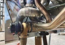
After assembly, it’s situated over the hot exhaust pipes, collector and muffler, keeping heat from rising back up into the engine compartment, fan shroud and radiator. One of the keys to a cool engine is how well you build this heat shielding. The most difficult area of construction of the shield will be how closely the top of the box surrounds each exhaust pipe. The smaller the gap, the more efficient your shielding.
This is why it’s a really good idea to build the box first out of thin cardboard so you can get an idea of what piece goes where, and you can easily trim the cardboard to fit perfectly. Then you simply copy the pieces in aluminum and end up with a nice little assembly.
When installing the tops of the box around the exhaust pipes, be extra careful not to cut the exhaust wrap with the sharp edges of the aluminum. The construction video has some really nice steps and tips for building this box, most of which aren’t found in the building manuals. So watch the tape a few times and copy the procedures.
If you make the holes around the exhaust pipes a really tight fit like you should, getting the aluminum on and off without cutting the exhaust wrap can be difficult. I invented my own cheater’s way around this problem that I like very much. I cut out the areas around each pipe as huge gaping holes so the two upper sections of heat shielding box would just slide right around the pipes with no bending or fuss. Then I made separate small cover pieces that fit around the pipes quite uniformly with just the right amount of gap, each held in place by more 8-32 screws and nutplates.
Look at the pictures and you’ll get an idea of what I did. It’s really much easier than what’s called out in the plans or videos, even though it uses a few more nut plates and pieces of aluminum. At this point the heat shielding and fan shroud should be trimmed to fit within the body panels. The tail boom must be mounted to get an exact fit, so I’ll have to finish this later, after we drag the ship out of the garage and put the boom on. For now, I put all the body panels on and did some preliminary trimming, just to get rid of the excess stuff. Check the pictures.
Muffling
The muffler can now be mounted, but once again, the boom and body panels must be installed to locate it exactly. I guessed at what angle and height it would be but will finalize the details with the boom in place later. The front or inlet section of the muffler is held to the collector with the exhaust knuckle, and the rear is suspended with steel strapping material bolted to nylon-laced rubber.
Fuel Systems
First, however, we have to mount the fuel tanks. And Brother, what a pain in the rear-end this is. Rest assured that the instructions in the manual do a good job helping the builder through this chore.
There are two fuel tanks mounted on either side of the ship and are near the center of gravity to minimize balance problems with full or empty fuel. They drain simultaneously so the lateral c.g. of the helicopter is also not affected. The tanks are made from a cross-linked polyethylene plastic material noted for its durability. Even though a similar fuel tank made from aluminum would be 10 to 15% lighter, there is no comparison in strength.
The first step is to cut out the areas inside the molded portions of the tanks where the fuel caps and fuel gauge sender will go. Cutting these holes requires care when using a drill. The tank walls taper inward just below the hole and can be damaged if nicked with a spinning bit.
Next, I washed out the tanks, making sure to remove all debris accumulated from the cutting and drilling. On the bottom of the tank I mounted the fuel strainers and fittings. Here’s another great update from previous kits. The old strainer had to be soldered together from a piece of screen. The new one is a more solid design of tooled aluminum and takes only a few minutes to install.
Now for the tank mounting. The tanks must be placed against the frame and moved and adjusted to just about where you think they should go after studying all the photos and drawings. The reason these are initially a guess-fit is that you must build and bend the bracketry required for tank installation, and there’s really not much to go by.
Then you assemble the body panels, making sure the tanks don’t contact the body anywhere. There’s a lower tank bracket already welded on the frame where the bottom of the tank is supposed to sit, but depending on how you’ve assembled the fiberglass body, you might have to raise the tanks or tilt them at a slightly different angle.
The most efficient way to go about all this is to first hold the tanks in place against the frame where they’re supposed to mount and note where they contact the frame. Then take away the tanks and glue rubber stripping in all these places, being generous to accommodate any adjustment or movement in the tanks on final installation. Next, hold the tanks in place on the frame with duct tape, then assemble all body panels that cover or come near the tanks.
Adjust the tanks accordingly, and when they’re sitting where they seem to clear the body and any other hindrances, you can then remove the body panels and begin to build the tank bracketry to match. On my particular ship, I had to raise both tanks a full inch off the lower bracket using rubber blocks, and thus the inside bottom of both tanks hit the top legs of the edges of the lower engine mount. I then had to grind off about 3/8 inch on both the engine mount legs so they wouldn’t dig into the tanks.
The tanks have molded insets where the engine mount legs are supposed to go, but mine didn’t line up quite right. Apparently other builders have had to do this as well. As I’ve said before, every ship is slightly different for various reasons, and builders must be ready to ad-lib!
Two brackets for each tank must be made, and each bracket is lined with the same type rubber stripping used on the frame under the tanks. For each tank, one bracket goes from top to bottom, extending the full height of the tank. This bracket actually does about 80% of the holding and thus should be pretty tight once you cinch everything down.
The other bracket surrounds the rear portion of the tank and checks any movement not maintained by the bigger bracket. One slight improvement made in the tanks for the 162F is that RW shaved down the top, rear of the tanks, thus increasing the amount of space between the upper rear body panel and the tank. For anyone who’s struggled with older RW ships, this is a welcome update.
Next the tanks must be taken off again and the inboard surfaces covered with heat shielding material. This stuff is held in place by its own self-adhesive surface, as well as with aluminum tape. At least it’s supposed to work like that. The plastic these tanks are made of somehow resists tape, no matter how much you clean the tank before! I suggest using the same yellow 3M glue that was used to glue the other rubber to the airframe.
You must restick the edges of the aluminum tape and some of the heat shielding. You’ll at first think it’s all gonna stay, but once you put the tank on the ship and there’s some expansion and contraction in the tanks, a lot of this stuck-on tape will unstick. So you can wait until you’ve mounted the tanks to see what edges and corners of the aluminum tape decide to unstick, but I promise that you’ll need more adhesion.
Friendly Help
It was at this point in construction that the due date for my baby was getting precariously close, I was traveling and gone more than half of every month, and for the next few steps in construction I wanted to speed things up by a month or so, so I called in the reserves.
An old friend and true veteran of RotorWay kits happened to be nearby and I took advantage of the timing. Homer Bell currently travels around the world, helping guys with their RotorWay projects. Homer has helped build numerous ships, and he’s one of the few guys I knew I could trust if I just pointed to something and said, “Let’s finish this!”
So for about six days straight, Homer and I worked feverishly on my ship and we moved things along quite nicely. We finished many small details and the rest of the fuel system, installed most of the electrical system, and we even finished the main blades. We worked about 9 hours a day, taking breaks only when we had to figure out whose tools were whose!
Yes, Homer comes equipped with a van full of tools, so make room for him. If you need some help along the way, he says he’s available. He told me we could print his phone number, but please don’t bother calling unless you’re going to hire him. All technical calls should still be routed to RotorWay. Homer’s number is 513/932-6500.
More Fun/Work
Back to the ship. Next, I built the fuel drain cock mounting bracket. It’s just a matter of copying the pattern from the template, cutting out the bracket, making the appropriate holes, and bending it to shape. This unit will be mounted on the bottom inside of the body tub, accessible through a hole under the ship.
The rest of the fuel installation is fairly simple, and involves only mounting a few components and running fuel lines to them. These items include the two fuel pumps, the fuel shut-off valve, the fuel filter, and the pressure regulator. All these items mount behind the seat back and onto the existing fuel rail.
The fuel rail is simply a square tube weldment that looks like another piece of the airframe, though it’s bolted, not welded into place. It’s called the fuel rail because all these fuel system components are bolted to it.
Once you get all the lines and components for the water, oil and fuel systems installed, the insides of the ship begin to look really complex!
Getting Wired
But the real spaghetti is next. You know you’re getting close to finishing an aircraft when you start to install the instruments and the electrical system, so here we are! And Oh, man! Has RotorWay made this a lot easier for the builder!
Why? I’ll quote a paragraph directly from some or RotorWay’s promo material: “The overhead switch/fuse panel, the airframe harness, and the instrument wiring harness have been assembled, soldered, insulated and tested ready for installation.”
That says it all. Look at the picture of the overhead switch/fuel panel as an example and you’ll see how much time you’ve saved. Also, every wire in the airframe harness has been cut to exact lengths with almost every plug installed, ready to be plugged together. On older kits, we were just given a big complicated wiring diagram, a pile of plugs and some solder plus a spool of wire! Good luck!
Don’t get me wrong, though. There’s still plenty of work to do, depending especially on how you wire your lights, radio, intercom, transponder, and blind encoder if you decide to use these items. I ended up taking a pretty lengthy route by installing a Bose intercom with separate flush-mounted headset interfaces. These are the older Type One Bose headsets, and the flush mount interfaces are about 5 inches deep. As you can see in the pictures, I decided to put the interfaces in the overhead panel and ended up having to completely reconstruct the switch panel box to house the new interfaces.
I had some extensive new wiring to do as well. Also, I used a King 97a com radio that has capabilities for remote scanning of 10 stored radio frequencies, as well as remote flip-flop for active and standby frequencies. This meant I had to run a new small wiring harness from the radio to the cyclic stick. Though this type of wiring isn’t difficult, it’s time consuming when you’re making plugs and making sure it all blends with your existing wiring.
Homer was long gone by the time I got to this stuff, and I think I spent another week on and off just with the extra wiring. You can see how those 350 hours of building time can become a lot more when you add your own stuff!
In the manual, the first step in the electrical section is preparing the instrument panel. This is one of only two areas in the kit where you get to do some fiberglass work. The instrument panel comes completely cut out, with all the instrument holes ready for the appropriate pieces of equipment.
First, however, you must glass into the instrument pod small pieces of fiberglass angle material for mounting the panel. We use the panel when locating the angles and make sure the panel lies flat inside the pod. Maintaining an equal lip all the way around the panel would be a mistake as you’ll bow the panel, and the digital display won’t mount correctly. If you do things correctly, the top edge of the panel will be in the pod deeper than the bottom.
The coolest part of the FADEC (fully automatic digital electronic control) system is the new digital display that mounts right in the middle of the instrument panel. It too uses the fiberglass angle material to be mounted, but with 8-32 screws and nutplates. I will describe what shows up on the digital display in the next issue. You’ve probably never seen anything like this in a homebuilt.
After mounting all the fiberglass pieces and getting the holes drilled and nutplates installed in the pod, it’s time to prepare the panel for the instruments. The kit comes with a stick-on black plastic material that will give the ship a professional look, but I chose to paint the panel instead. I wasn’t exactly sure what my external paint design will be, so I painted the panel black and white with that new spray splatter stuff. So no, it won’t be a typical corporate looking ship. We’ll see what happens to the outside later.
Back to the Wires
Next, the airframe wiring harness needs to be laid out on the frame. I paid close attention to the numbers on each wire and its route to avoid areas where other parts of the ship could damage the harness. For example, when running the wires along the side of the airframe, I put them below or to the side of where the seatback will be sitting.
It’s also a good idea to encase the wires in some sort of protective material wherever you think chafing might occur. At electrical supply places or Radio Shack, you buy spaghetti nylon wrap or plastic tubular material with a slit down the side. Though not fire resistant, both these products are great for making your wire installation tidy.
Also hooked up at this point are numerous components including the alternator, throttle position sensor, primary and secondary fuel injectors, water temp sensor, and air temp sensor. (Are you getting hints about what might show up on the digital display?)
I attached wiring to the frame using the supplied nylon tiewraps. With the 162F’s current second-generation FADEC and wiring configuration, the location of a few of the components has changed, making engine access a lot easier. A large aluminum tray must be built and mounted to the seatback section, but under the passenger’s collective slot inside the belly of the ship. Both electronic control units (ECUs) go in this box, taking them off the actual seatback. This saves a lot of room, and now there’s just a big access door behind the pilot.
The inboard and outboard ignition packs are mounted to the back of the passenger seat, and spark plug wires are labeled for their routes. I used the plastic spark plug wire separators as necessary. These spark plug wires shouldn’t touch each other or any other components. The current sent from the ignition packs is a delicate spark, and wires touching each other can cause unwanted interference.
Next I cut out the overhead switch panel hole in the cabin roof panel and routed the plugs and wires out the hole. At this point the builder decides whether to add anything to the switch panel such as substituting circuit breakers for the supplied fuse holders. Fellow builder Mike Sherick did this, and he even made a customized panel with each switch and circuit breaker labeled with stenciled lettering.
This really looks professional and is pretty impressive. I added a couple of switches to the panel as well as the Bose interfaces, so I had a great time trying to get everything to fit. Whatever is added has to fit within the fiberglass doghouse! There is more height available toward the rear of the panel.
When routing the wiring out of the fiberglass cover and to the airframe wiring harness, I secured all wiring away from the main shaft. If one of the spinning hose clamps or the rotortach magnets on the main shaft snagged a wire, you’d be in the middle of a hell of a mess. It’s happened before.
Using the correct template, I cut out and drilled the inertia switch bracket, which is mounted under the main bearing flange in front of the main shaft. These switches are safety devices that are supposed to shut off the fuel pumps in the event of a really hard landing or crash. With that 54 psi of fuel pressure, this sounds like an important safety addition to the ship.
Back Together
After all your wiring is done, you can begin to piece the body back together. I Started by installing the seat belts. I used some of the same rubber trim that will be used around the bottom edge of the dog house and around the tops of the skid pants as trim in the seat belt holes to prevent chafing of seat belts.
Next in construction comes the cabin comfort package. This is a system designed to pull hot air out from the fan shroud and plumb it into the cabin on a cold day, or it will pull ram air from a scoop mounted underneath and into the cabin for cooling on a hot day. While it all looks pretty nifty, I live in Southern California, where it’s never really too hot or too cold. So for the sake of simplicity and weight saving, I’m leaving the cabin comfort package off.
Wow! We covered a lot of construction this time. Next issue we’ll finish a few details and then we’ll yank her out of the garage. Then we’ll install the tailboom, tail rotor, horizontal and vertical stabilizers and main rotor blades, and we’ll get her rigged to hover!
If all goes well and if I can talk Editor Dave Martin into it, we’ll extendd these articles one more issue after that and talk a little about what happens at RotorWay’s flight school. We’ll also get some air-to-air photos from Mike Sherick’s 162F to mine and vice versa!
Thanks for reading.
FOR MORE INFORMATION on the RotorWay International kit helicopter, contact the company at 4140 W. Mercury Way, Chandler, AZ 85226; call 602/961-1001; fax 602/961-1514; www.rotorway.com.


