 Building an eXenos electric motorglider is a lot like building a regular Xenos—at least until you get to the stuff forward of the firewall. In fact, just about the only differences you’ll find will be in the wiring preparation in the cockpit.
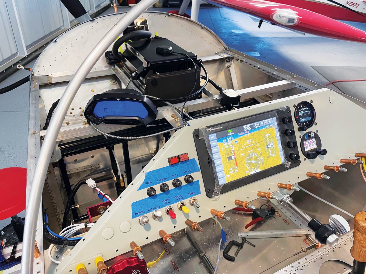
Most Xenos (Xenii? Xenee?) are fairly simple when it comes to wiring. There are engine ignition controls for whatever gas engine you’re using, a master bus, some fuses or circuit breakers and a radio. There will probably be an electronic variometer and a simple EFIS. But nothing terribly complicated—it’s not that kind of airplane.
In our case, we had the controls for the AeroVee engine, a master switch, four circuit breakers for the EFIS, radio and vario—and a spare breaker just in case we ever wanted to add some lights. When it came time to prepare for the electric conversion, we repurposed the ignition switches to control the motorcycle powerplant and everything else stayed the same. Easy.
To modify our project, the first step was removing stuff. The engine came off first, reversing what we had done to install it—four bolts then disconnect the wiring and controls. With the engine safely off the hoist, we turned our attention to the firewall, which had a surprising number of holes in it.
Fortunately, AN3 and AN4 bolt holes in a firewall are really easy to patch—just use a short bolt, a fender washer, a regular washer and a nut on the other side. Bolts aren’t stainless, but they are steel and much thicker than the firewall material—they make good “patches.”

To fill larger holes, like those where the control-cable eyeballs had been, we used some scrap stainless and made a patch using the original eyeball mounting holes and stainless steel #6 screws to attach them. The product is plenty fireproof, and if you put all of the bolt heads on the forward face, they actually look pretty good. With all that removed, the only thing remaining firewall forward is the motor mount and landing gear—but let’s leave that for now.

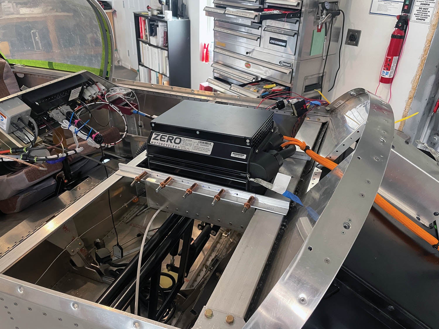
Behind the firewall, we removed the fuel tank and its suspension straps, cleaning up the area ahead of the panel and above the pilot’s and passenger’s legs considerably. This space doesn’t remain empty, however: The high-rate battery charger mounts behind the firewall since there isn’t really a convenient spot for it up front. Plus, putting it where the fuel used to be helps the CG a bit.
To support that battery charger, we took a piece of 1×1-inch aluminum angle and built a cross-cockpit brace, attaching it in the holes that were previously drilled for the aft fuel tank hanging strap. That gave us plenty of room between the lateral top firewall brace (heavy aluminum angle) and the new cross-brace to fit the charger when we had it ready. Lastly, we removed the Sonex throttle and installed a push-pull throttle in the middle of the cockpit, hanging on a bracket underneath the instrument panel. This gave a clean design and allowed it to be reached from either seat. Since the throttle is not as important on a motorglider as on a powered plane, it didn’t need a place of importance in the pilot’s left hand. And the speed brake handle is over there already anyway, so putting the throttle in the middle meant less clutter.

Mounting the Motor
With the old systems removed from the firewall, there’s still one major change to make, and that’s the engine mount. Sonex builds different mounts for different engine packages and now has the CAD design and welding experience to provide the mount for the Zaero re-drive. We were the prototype customers, and ours fit perfectly, even using the same shims we had used with the original AeroVee mount. Since the shims are used to take up minor variations between mounts and airframes, that is a pretty good statement on the factory’s dimensional control.
Removing the old mount means the landing gear comes with it, so you need to block the fuselage up on a work stand or sawhorses—make sure to raise it enough to get the wheels clear of the ground by a couple of inches to allow for working room. We left the gear legs, wheels and tires on our old mount when we removed it, and after taking out the eight 1/4-inch machine screws that attach the assembly to the fuselage, it was easy to roll it right away.
The next job was worth taking time to get exactly right—lining up the gear legs and drilling them to the new engine mount. The bolt holes that pass through the gear legs to attach them to the mount are about an inch farther down from the top of the leg than on the AeroVee mount, so new holes have to be drilled. Fortunately, the mount itself provides tubular “drill guides” as part of the bolt support, and these can be used to mark the exact location of the holes once you have used the Sonex method for setting the toe-in measurements.
You could use the mount to fully drill the holes, but we used the mount’s drill guides to simply mark the locations with a drill, then removed the legs and transferred them to our mill to drill the through holes. You can use a good drill press and vise to do the same thing. It pays to take your time to get the alignment correct!
With the holes for the bolts drilled, we bolted the gear legs back in place on the new mount, then tucked it up into the fuselage to match-drill the holes to the airframe. Use clamps and straps to hold it in position while you do this, and the end result will fit perfectly. If your eXenos mount is the first one to be installed on your airframe, the process is the same—just use the pilot holes to locate the holes. Having eight 1/4-inch Clecoes really helps at this point—they quickly and accurately hold and locate the mount as you drill holes. And don’t install your bolts at this point—the mount will be coming off when it is time to install the battery, so Clecoes will do the job for now.
Stripping the Bike
Disassembling the bike took us about two days of work, and required several people to do the final work safely. Most of the process was a one-man job, however, so follow along as we tell you just how an electric bike became a workbench full of airplane power!
The first thing you have to come to grips with is that Zero Motorcycles—the manufacturer of our 2019 DSR bike—has no intention of letting their documentation go out to the general user. They don’t provide a maintenance manual, and there are no drawings available from the factory. Their business model is to provide not only bikes but complete service through their dealers and they are not about to make it easy for a do-it-yourselfer who wants to explore the mechanics of their machine.
The good news is that the ingenuity of the tinkerer should never be underestimated. There is a fairly strong user community online, users who have maintained, modified and repaired their own Zeros and documented the processes along the way on a website at zeromanual.com. The website is the single biggest collection of information on the bikes that we could find and includes a user-developed service and maintenance manual, as well as the best available electrical schematics.
The only manual, in the form of a wiki, is a great place to find details on how the bike comes apart. It takes a bit of nosing around, and you won’t always find exact instructions for your particular model, but Zero tends to keep doing things that work, so once they have a product, they tend to use the same design in subsequent years. For disassembly, we found that the online wiki tracked our bike very, very closely. In fact, I can’t think of a single instance where it was misleading or even inaccurate.
Safety First
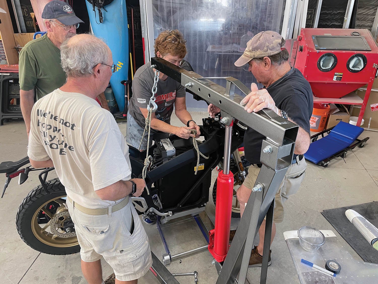
Before we get going, let’s point out a couple of things. First, the Zero is a heavy motorcycle, with no center stand. That means it is pretty unstable to work on unless you have a motorcycle lift. If you don’t have one, you might consider getting one—it will make final removal of the battery much easier. Your friendly Harbor Freight store has several models. We have one of their more expensive units that we use as a single-point jack for our little SubSonex jet, but I would consider getting one if I was just disassembling the bike.
Regardless of the jack, consider an engine hoist that you can use to “hang” the bike during some disassembly steps. Rig it as a safety system, not actually lifting the bike, but ready to catch it if it goes sideways. You’ll need something like this to remove the rear swingarm to get at the motor anyway. As we said, this is a heavy bike and if it goes over, you might need some help getting it back up!
The other thing to remember is that you are working with a 120-volt battery filled with a lot of kWh! Make sure to turn the key off and remove the key early in the process. As soon as you can get to the main battery connector, pull the plug—this will de-energize the harness and render the rest of the job safe. Anything that has enough stored power to lift a 1000-pound aircraft into the air needs to be respected.
Taking It Apart
The Zero motorcycle is a well-crafted consumer product that has a lot of trim pieces to make it attractive. That’s all got to go! So the first thing you’ll be doing is removing plastic trim panels on both sides and in front of the battery that are attached with screws in a pretty obvious manner. Note that you’ll be using metric tools for pretty much everything—metric Allens predominantly, but also some metric hex wrenches and a Torx bit or two.
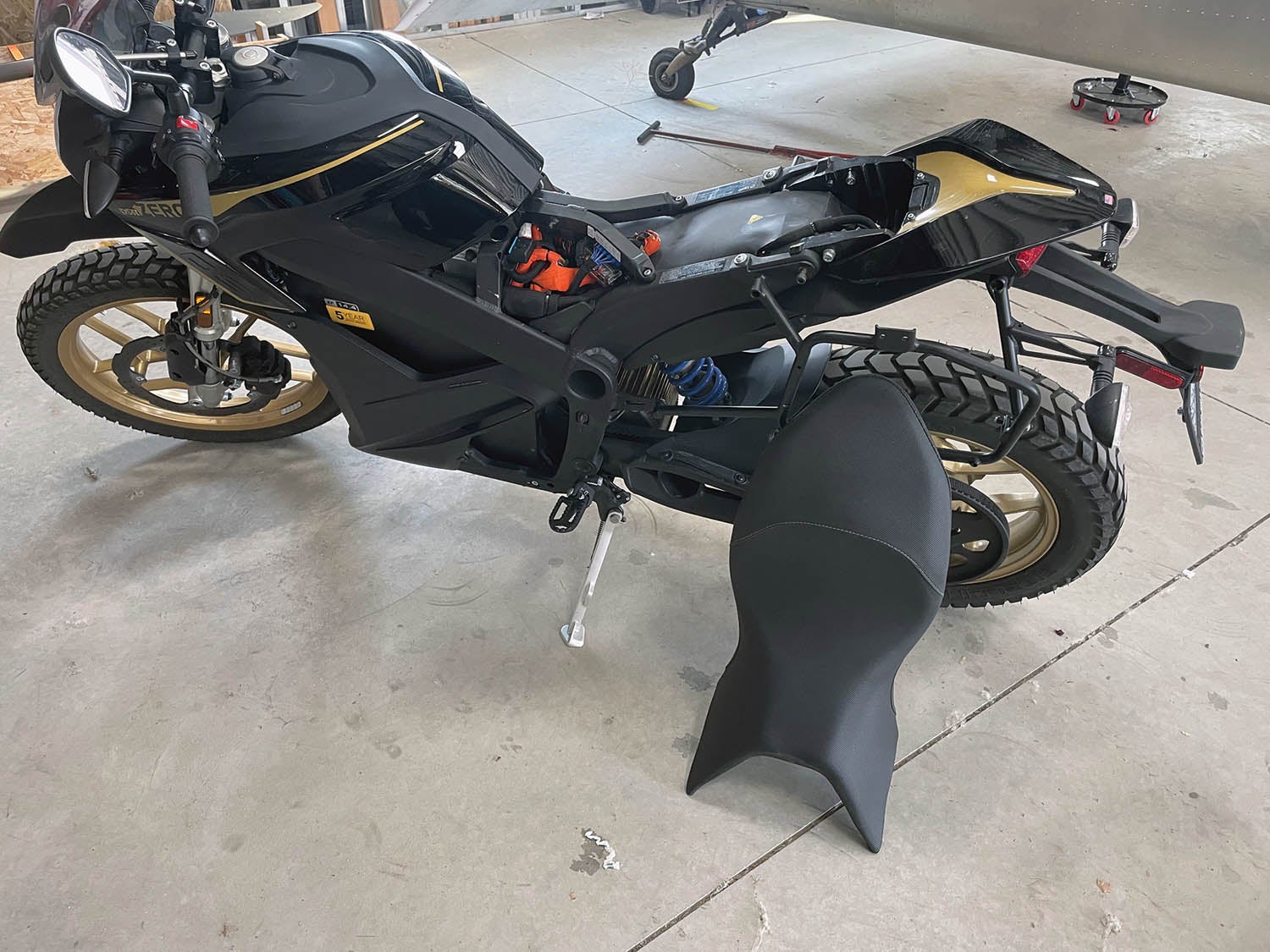
After the battery coverings, you’ll need to remove the seat and “tank.” (It’s not really a tank—it just plays the part.) Hopefully, you have a bike with the optional Charge Tank—a large, fast battery charger that uses standard e-vehicle charging-station plugs and 220-volt feeds to charge the battery in about an hour and a half. This is in contrast to the stock, built-in charger that takes 110 volts and about 12 hours to fully charge the bike. The Charge Tank is hidden underneath the “fake” gas tank—so you’ll need to remove this as well. While you’re removing plastic, take the rear trim pieces off—this gives you access to the tail and rear turn lights and connectors.
As an engineer, I was quite impressed with the detail that went into the design of integrated parts—giving me a hint that if they spent this much time on trim, they probably did a fairly good job on the electrics as well. For instance, there are screws that hold the rear trim in place that could only be turned with a right-angle screwdriver because other plastic is in the way. But, the designers drilled a hole through that other structure, lined up with the screw head, so you can insert a straight screwdriver through the offending part. The hole is barely noticeable because it is in the shadows.
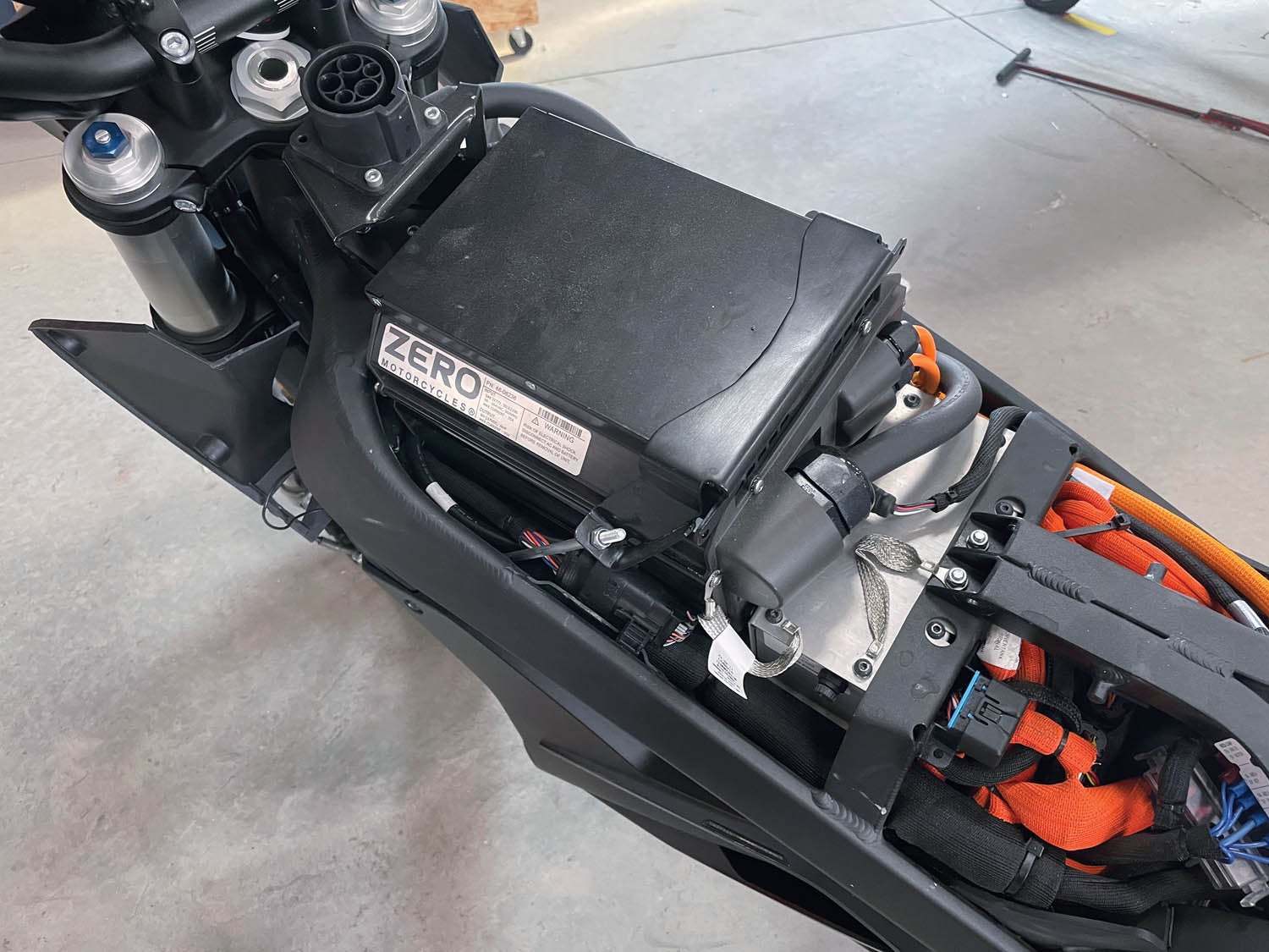
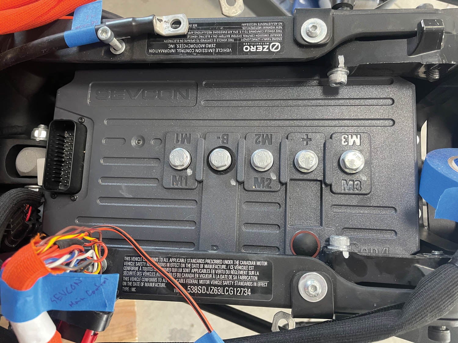
Under the seat, you’ll find the big, massive motor controller—the thing that handles all the current between the battery and the motor. Disconnect and label the big wires on its top surface—three go to the motor, two come from the battery and a couple more come from the battery charger. Once you have those cables off, the unit is held in with just four bolts—easy, huh? Well…not so fast. The front bolt on the right side is interfered with by a casting on top of the mono-shock, so that needs to be removed. Hoist the bike just a little to unload it and the top bolt can be removed, then the bottom. Swing it out of the way and remove the controller.
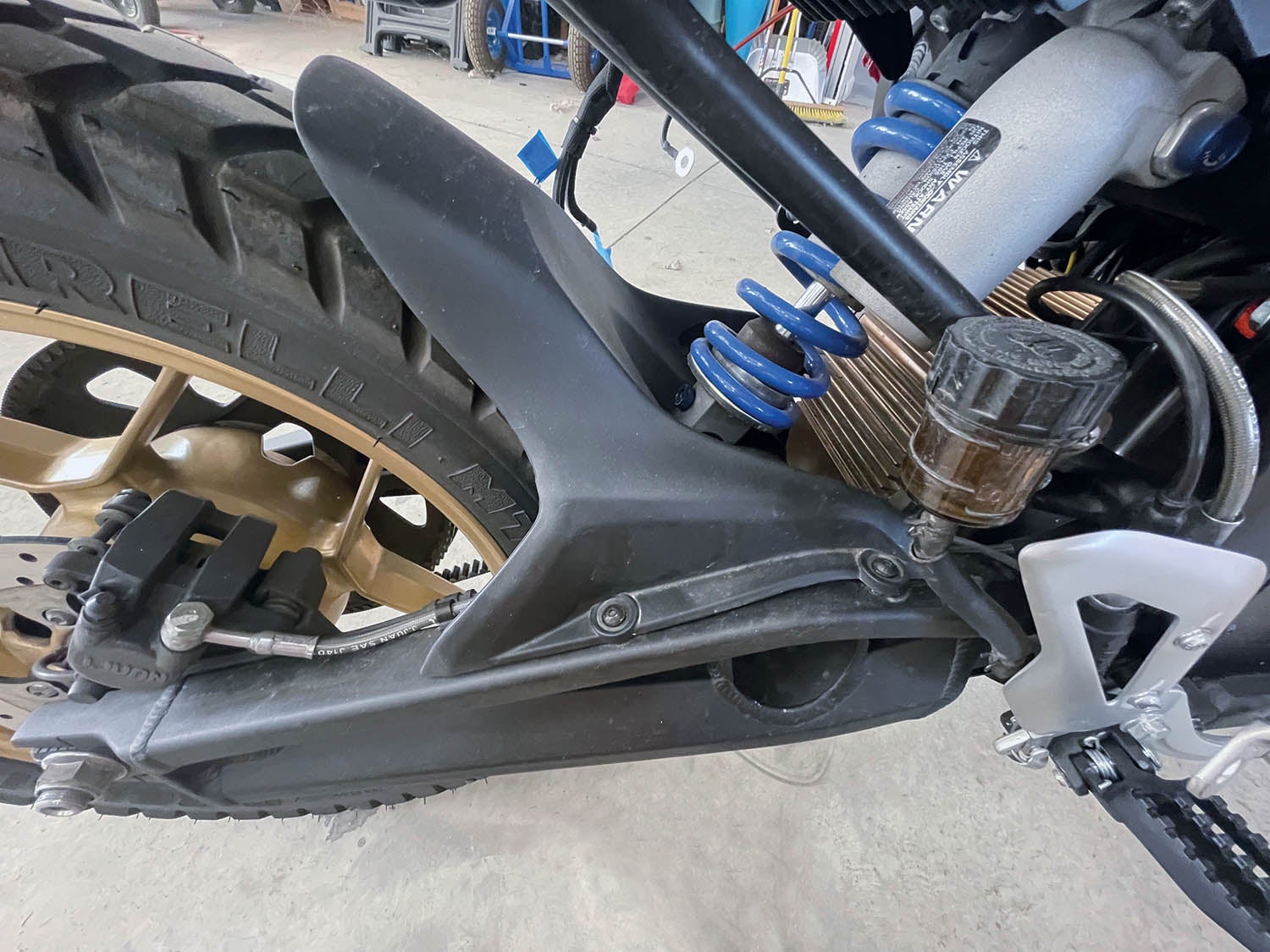
Much of the bike disassembly is that way. To remove the motor itself, you have to get the swingarm out of the way. So while the shock is removed, pull the two big bolts that hold the bearings for the swingarm. You can leave the rear wheel in place, but you need to remove the belt—it will come loose when you remove the pivot bearings. Oh, and there are some small plastic mud guards to remove. And you need to remove the rear brake pedal because it is in the way. With the swingarm bearings out, the whole rear end comes off, so have the weight on the hoist!
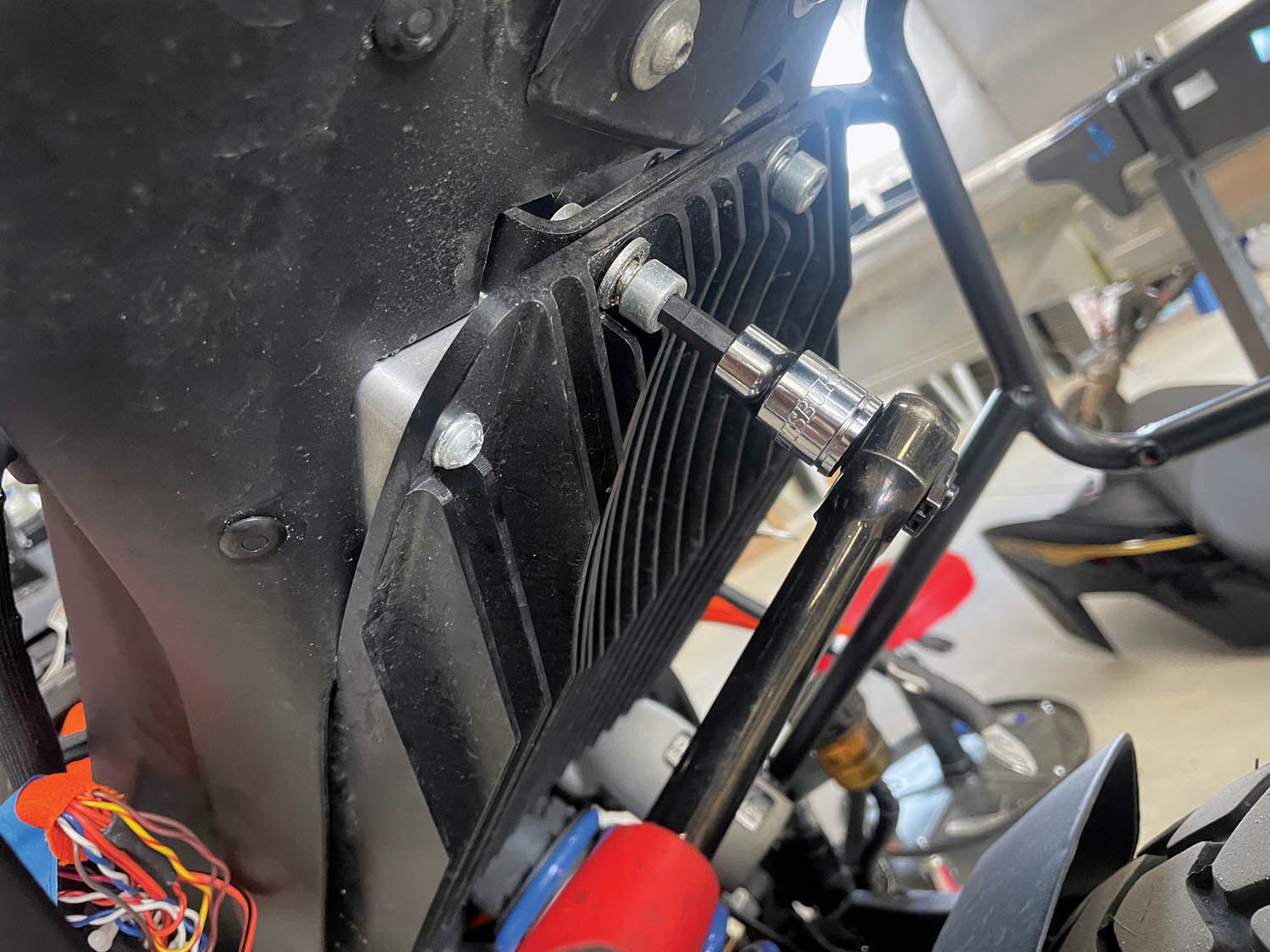
Removing the motor is a matter of pulling eight bolts, four on each side. Did I mention that they are all the same, except one? Seven of them use an Allen wrench socket—the eighth needs a Torx socket. Harbor Freight is your friend. With all eight bolts out, the motor slides out and down to come out of the bike. We put the swingarm bearings back in at this point and reconnected the shock so that we could let the bike support itself and could roll it around later on.
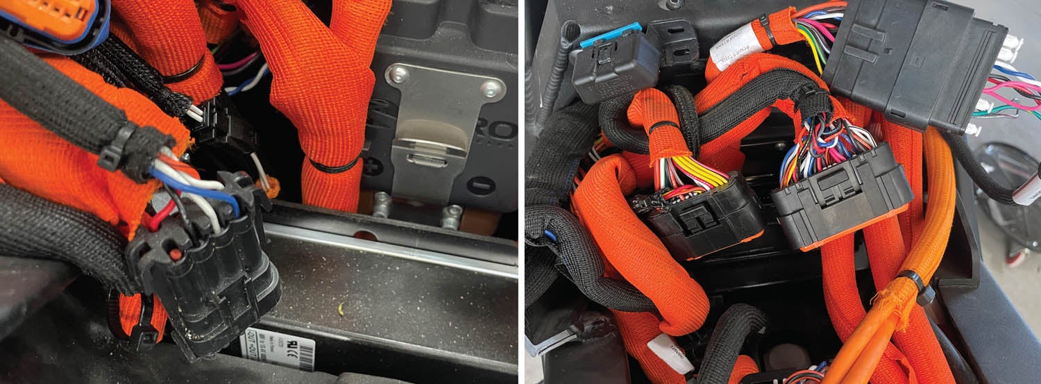
Take a break from heavy stuff, and dig down beneath the front of the seat area to take out the “main bike board” (the computer) and the DC to DC converter.. Some of the bolts are in fairly cramped locations, but it’s all doable. The online maintenance manual had some good tips here—use it for reference. Now head up to the instrument cluster area—remove it and start cutting cable ties and unplugging cables. When disconnecting things, always make labels so that you know what things are for. Proceed with disconnecting and freeing the wiring harness throughout the bike—it all comes out.
The last big blivit to remove is the battery. But before that, you have to remove the bottom skidplate and the 110-volt battery charger beneath it. You won’t be using the battery charger, but take care of it anyway—I was told it can bring $500 on the used market!
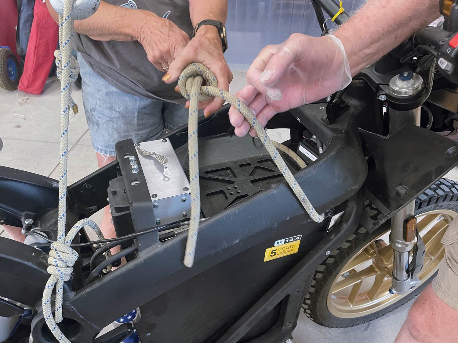
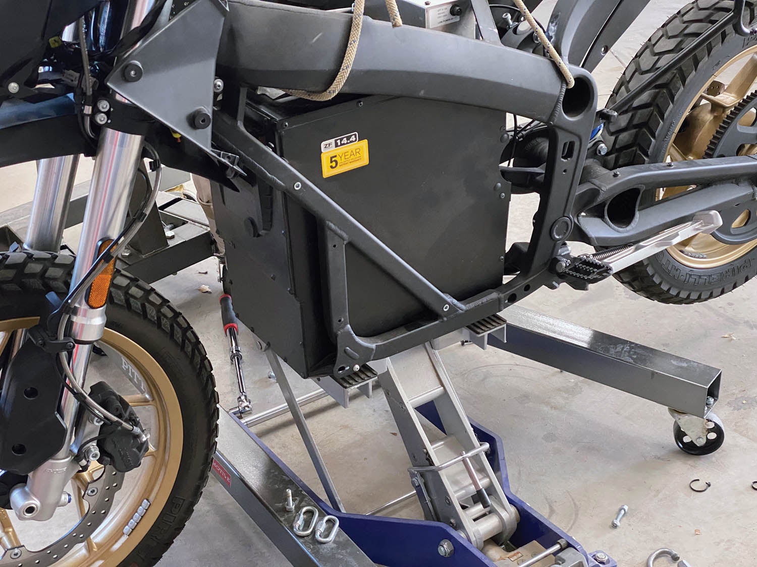
At this point, everything is out but the battery—it is held in with only four bolts, all near the bottom. Before you can remove them, you need to get a low-profile jack underneath the battery to take its weight—we used the motorcycle jack. Then rig your engine hoist to the frame of the bike. You are going to remove the four battery bolts, lower the battery as far as you can with the jack, then hoist the motorcycle off the battery! Sounds odd, yeah, but the battery goes in and out of the bottom of the bike. The battery weighs 180 pounds—so get some help for this. Once the battery is clear of the bottom of the bike, roll it out and let the carcass of the bike back down to the ground.
If you haven’t already, finish stripping out the harness—it all comes out, just cut cable ties and disconnect from peripheral equipment (such as lights and horn) as required. The toughest thing to disconnect is probably the ABS connector—it is really squeezed in tight in front of the fuel tank. You might have to use a long screwdriver to trip the keepers on the plug and then say a few bad words to get it out. Remember that you won’t be using the ABS module, so if the worst happens and you break the connector, it isn’t a disaster.
Stripping the Harness
At this point, you’re done with the bike itself—roll it out of the way and throw a tarp over it. What you do with the remains is up to you—we stored ours up next to the wall in the hangar for future disposal. While it is nice to think about having the ability to put the bike back together, once you have stripped the harness, that really isn’t going to be a realistic option.
Stripping the harness is mostly the job of taking out the stuff you won’t need for the airplane. Things like lights, turn signals, ABS, horn—it can all go. Doing this without a drawing would be fairly stressful. Using a mostly accurate drawing (from zeromanual.com) was much more comfortable—but don’t trust the wire colors to always correlate. Confirm before you cut by checking wire counts in connectors, seeing if the wires are going where they are supposed to be going.
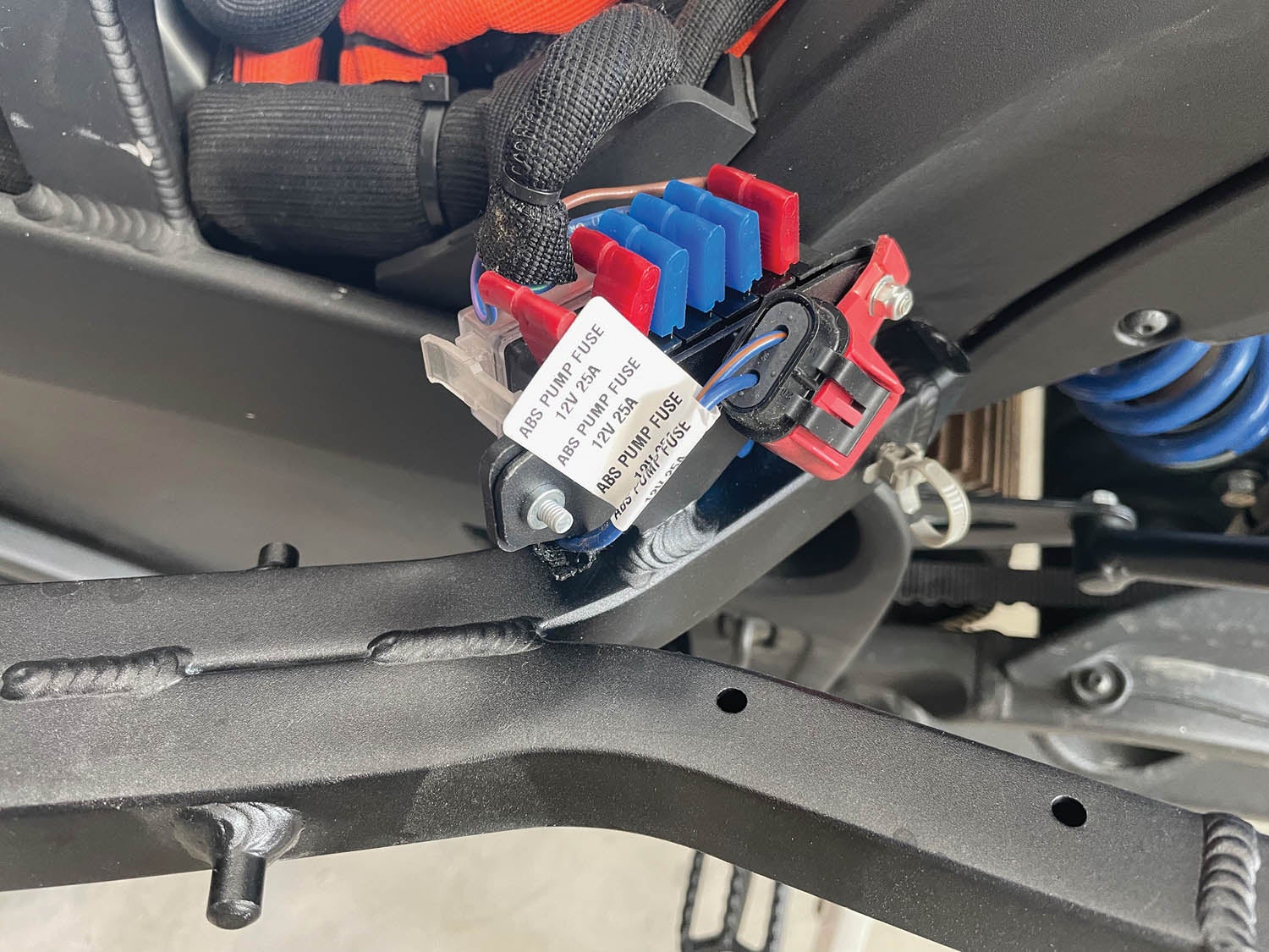
Fortunately, it is almost as simple as saying “if it uses 12 volts, it goes!” However, you are still going to want to have some 12-volt power for avionics and aircraft accessories like lights, so look for the output of the DC/DC converter—it goes to the supply side of the fuses on the fuse box—and make sure to keep it. You’ll find a couple of 14-gauge wires (mine were blue) coming out of the fuse box that you can route to your instrument panel to power things you’ll want. Most of the 12-volt fuse box wires are going for the ABS and horn—you can do away with those entirely and simply keep the fuses installed as spares. I ended up with only two fuses that powered anything.
Zero uses split-wire looming to beautify their harnesses, and this material can be opened and reused strategically to make a very nice harness in the airplane. Just remember one thing—unless you go to the effort to replace every wire and re-pin every connector, you are going to be flying with automotive wiring, not the Tefzel that we usually use in aircraft. To be honest, homebuilders have been using non-aviation wire for generations, and while it is far from my first choice, the risk of messing up the harness probably outweighs the small risk of flying with the PVC insulation on the automotive wires. Just acknowledge the risk and make sure you wire with appropriate sizes and fuses.
A Bench Full of Parts
So that’s it—how to disassemble an expensive motorcycle and create a workbench full of parts. All you need to get there are a few metric tools and the strategic help of some able-bodied friends. This is a good time to clean everything up—remove any traces of road dirt, grease or grime—and inspect the components just to make sure there is no damage to connectors or housings. Since you’re probably using a relatively new bike, everything should be in good shape—but since you probably bought it used, it’s better to have a look and make sure.
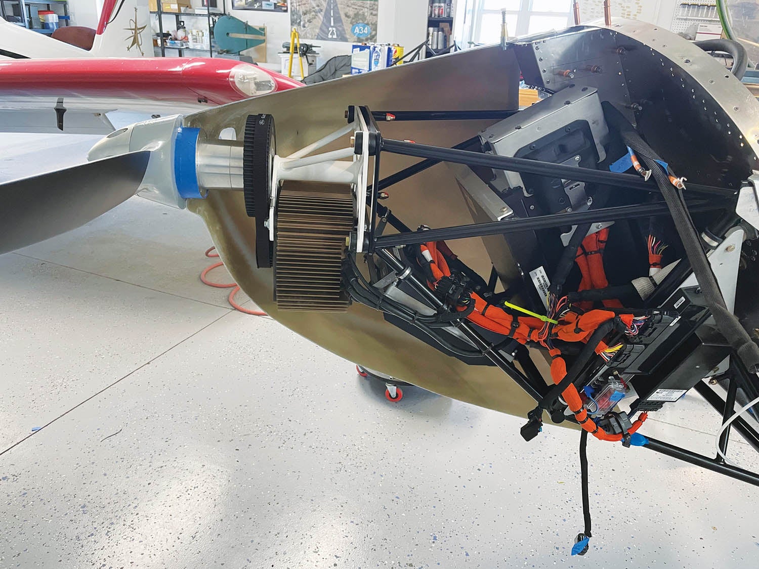
Next time, we’ll talk about how you take the components and reinstall them in the nose of an airplane to make a working electric powerplant!
![[Credit: Sonex]](https://www.kitplanes.com/wp-content/uploads/2026/07/unnamed-6.jpg?w=218&h=150&crop=1 "Sonex Renames High Wing the Phoenix")


Thank you for this informative article. I am building an E Xenos as well and look forward to seeing your progress. Tim Drager.
Comments are closed.