
Last month I discussed the slump and drape molds that Steve Cogswell used for making fiberglass concealers/accessory panels for his RV-8. (Also see “A Tale of Two RVs,” June 2022.) We got the ball rolling by making the drape mold for the recessed concealer. This month, I’ll show how to make the slump mold for the protruding concealer and introduce the rotary table as a way to drill perfect bolt patterns. The bonus for this project was my visit to Steve’s hangar to see his layup procedure.
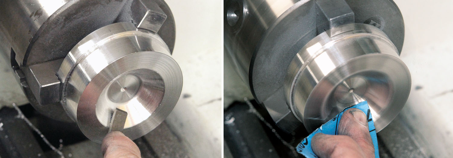
The machining procedures for the slump mold are essentially the same as what I showed last month: face turning, tapering using the cross slide and polishing. The major difference for the drape mold was that I didn’t have a tool to make the outside radius, so I hand filed the radius by eye. If you follow this column, you know that I always use a hand file—with the lathe running—to deburr outside edges of lathe parts and a hook tool (a small handle-mounted scraper) to deburr inside edges. A quick touch with either is all it takes to dress off burrs. Making a radius by hand filing is fundamentally the same as deburring; it just takes longer. If the dimension is critical, you can use a radius gauge—homemade or from a professional radius gauge set—to check your progress. To make a large radius on an inside edge like the drape mold, a hook tool won’t be enough—you’ll need to use a file with a half-round or convex profile. A round file will work too, but it will take longer because less teeth are in contact with the work.

This is the first time I’ve used a rotary table for a KITPLANES® project. Before the era of CNC machines, every machine shop in the world probably had a hand-crank rotary table. These days, not so much. Despite this, they can be found in many home improvement stores and hobby shops. Anyone doing exclusively hand-cranked machine work should consider a rotary table. They are indispensable for milling arcs and circles and for indexing hole patterns or milling teeth for sprockets and gears. You will find that rotary tables come in sizes ranging from those that are appropriate for home use to those that require an industrial crane to move. You might stumble across a good deal on an 8- or 10-inch rotary table, but if you have a small bench mill or mini mill, even a 6-inch rotary table will likely not be practical. Weight is also a factor: The 6-inch table used for this project weighs about 30 pounds. A 10-inch rotary table? About 100 pounds! That’s something to keep in mind if you’re working by yourself.
A rotary table is similar to an indexer. The obvious difference is a rotary table has a crank that drives the table via a worm gear, and an indexer rotates freely and must be locked in place by an index pin and clamping screw before any machining. The most common ratio for rotary tables is 90 turns of the handle for one revolution of the table. A rotary table will have T-slots for hold-downs to facilitate mounting fixtures or tooling plates. Most rotary tables can be used with dividing plates that convert it into a precision dividing machine for making equidistant holes or for spacing gear or sprocket teeth. Using a rotary table as a dividing machine isn’t complicated and there are a number of online references and videos. A good place to start is the tutorial posted by littlemachineshop.com for their 4-inch rotary table.

I figured the Cogswell molds would be a good project to demonstrate a rotary table because it is a great way to make a highly accurate bolt pattern. I knew that if I had marked the holes by eye, they would have been ±0.020 inch, at best. While that may be OK for some, Steve is Mr. Precision and I knew that he would surely notice anything that wasn’t within ±0.003 inch—so I just had to use the rotary table!
Although my rotary table has a set of dividing plates, I simply used the degree graduations and cranked the handle as needed for the hole spacing (22½ turns = 90°). Even more basic, I set up the rotary table on the drill press and used a spotting drill to mark the locations to be drilled later.
Here’s a quick rundown of the fiberglass layup procedure Steve used.

The cloth required for this project is standard E-glass fiberglass cloth, 38 inches wide. According to the Aircraft Spruce website (part number 120-38), it has a “crowfoot weave, which contours nicely” and is “excellent for model building.” It has a weight of 3.1 ounces per square yard. Using heavier fiberglass or a different weave will result in the cloth not conforming to the mold contours.


Steve used a two-pronged approach to mold release: Meguiar’s Mirror Glaze Mold Release Wax, followed by a mist coat of Fibre Glast PVA Release Film #13.
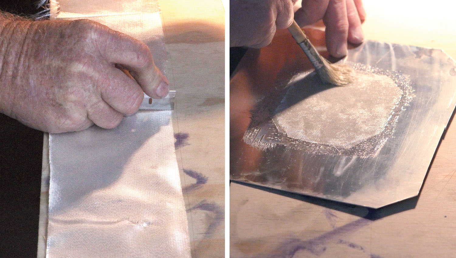
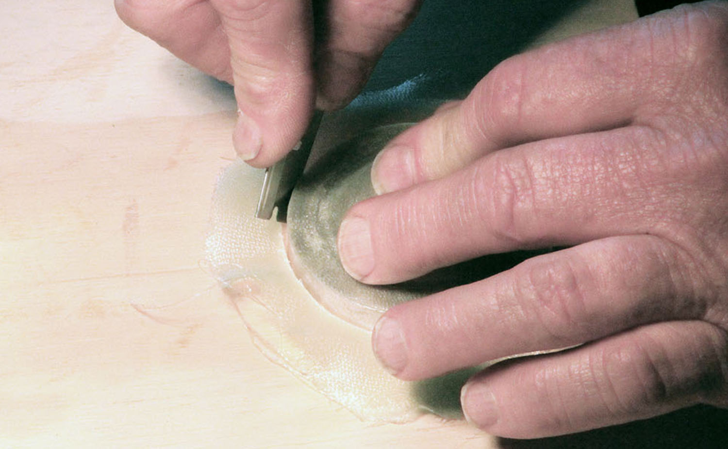
After cutting out the cloth to overhang the molds by at least 3/4 inch, Steve set up a task light with an incandescent bulb to radiate some heat onto the molds. While the molds warmed up, he used a cheap chip brush to wet out five layers of cloth on a sheet of clean aluminum. Steve used West System 105 Epoxy Resin with 206 Hardener (slow). He allowed each layup to set about 10 minutes. After 10 minutes, he peeled the fiberglass layups off the aluminum sheets and gently positioned them over the molds, whereupon he used the end of the brush handle and the end of a tongue depressor to carefully push and persuade the layup to conform to the contours of the mold.


I’m surprised to hear that heating the molds “extends” the curing process. With all the resins I’ve used, curing would be sped up (sometimes substantially) by the extra heat.
I have not used West Systems epoxy to build anything, but with vinylester and most polyesters I’ve used in building my Glasair, we use heat to accelerate curing, not to extend it.
The molds seem to turn out beautiful parts! I wish I had your expertise and your workshop. Thanks for sharing the techniques.
By extend, I think he meant advance the curing process
Comments are closed.