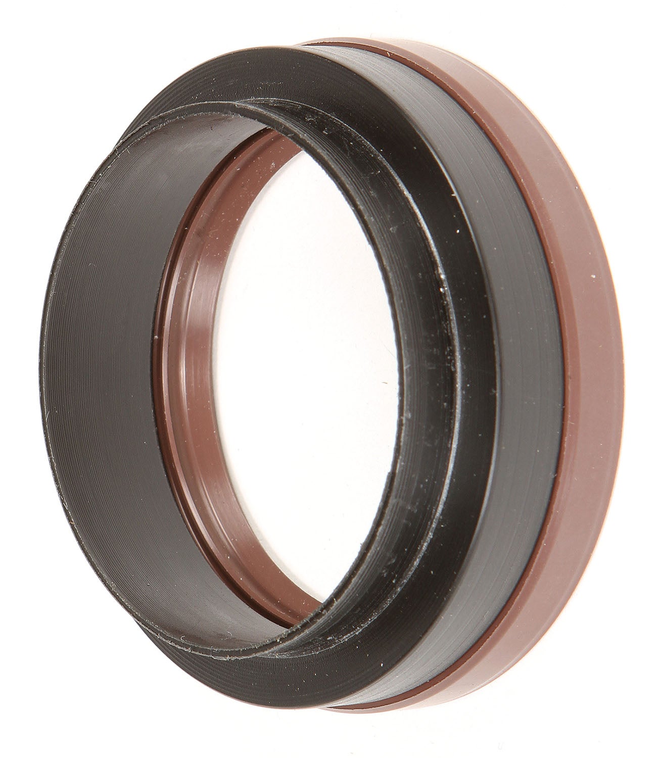
Radial oil seals, the kind found on rotating parts such as crankshafts, cam shafts and axles, are wear items and occasionally need to be replaced. While removing a seal sometimes presents a challenge, the ultimate success or failure of a new seal depends on the installation. Using the correct tool can help both maintain alignment and prevent damage to the elastomeric material when pressing or tapping a new seal into place. This month’s project shows how to adapt an off-the-shelf tube into a proper seal press sleeve. Note that this tool is specific for installing one-piece seals with a garter spring. These are common on automobile-based aero-conversions and modern aero engines such as Rotax and Jabiru, but legacy engines sometime use two-piece or O-ring oil seals (see “Maintenance Matters: Crank Seal Replacement,” June 2018).
Removing Old Seals
Seals being replaced during an engine or gearbox overhaul can often be pushed or pulled out with hand pressure or a light blow from a rubber mallet using a sleeve or punch. If a seal is stubborn or in an obstructed location and must be pried out, a flat-blade screwdriver will usually do the trick. If the seal is glued in, it may get tweaked a bit, but it’ll be discarded anyway so don’t worry about it. On the other hand, you must be extremely careful about the seal housing. Care must be taken not to damage the bore or the seating surface. The ultimate authority on seal removal and replacement is the overhaul manual for your engine.
Removing a seal on an assembled engine or transmission with the shaft in place presents a more challenging scenario. In addition to the seal housing, you have to be mindful of the shaft. While you can find a number of “shade tree” mechanic techniques floating around on the internet (including one that suggests drilling and screwing sheet metal screws into the seal face), the proper way is a dedicated seal puller.
Seal pullers come in a variety of styles. The plethora of options seem to go hand in hand with the innumerable scenarios auto mechanics face when squeezing into various engine compartments. Fortunately, airplane engines are a lot easier to service. Most are at a comfortable height, and with the cowling removed, access is relatively unobstructed.
Installing a New Seal
As previously mentioned, the overhaul manual will be the source for an exact procedure. Generally, you can expect instructions to clean away any residue or sealant left by the old seal and inspect the housing, seating surface and shaft for scratches or deformities. While most leaks are caused by old seals that are worn or have lost their elastic properties, occasionally the leak may be caused by something else. Close inspection of the shaft and seal housing is essential to avoid a do-over.
Check the new seal. If the sealing lip is wavy or split, toss it and get a new, new one. Seals are cheap compared to the time and effort it takes to replace them. I always buy two, just in case.
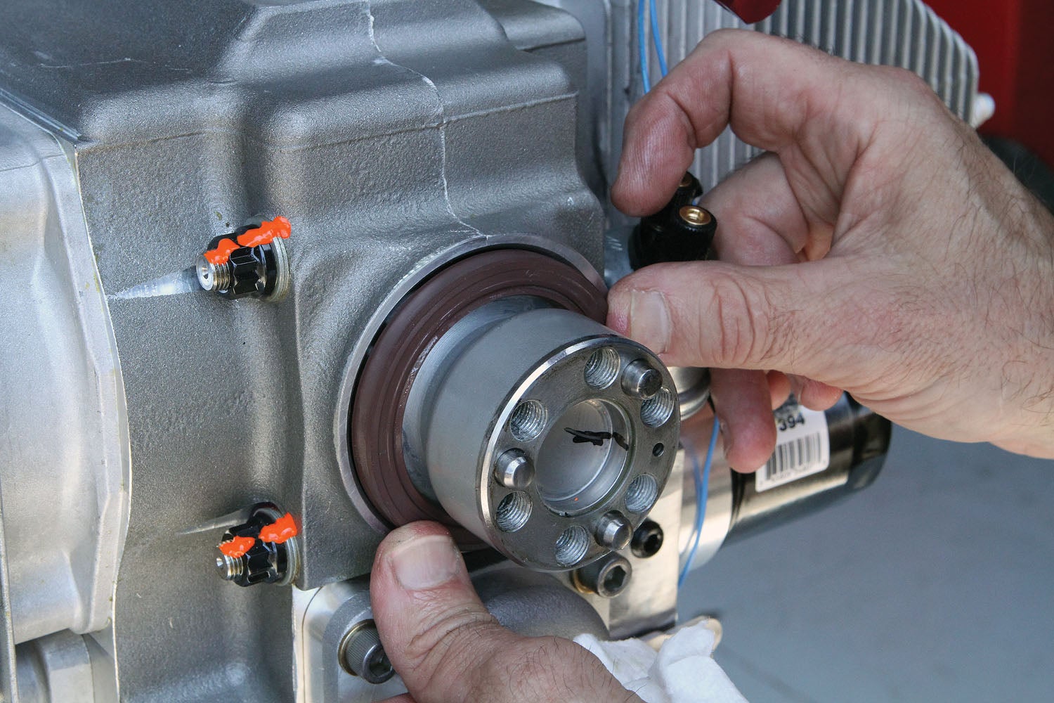
Prep the seal inside diameter (I.D.) and shaft with lubricant. Usually this is engine oil, but the engine manufacturer may recommend greasing the seal.
Prep the outside diameter (O.D.) of the seal according to the engine manual. Depending on the manufacturer, this could be either a sealant or lubricant.
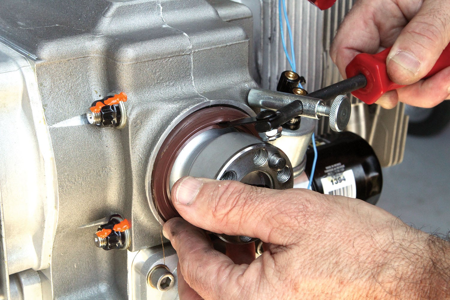
Never hammer directly on the surface of the seal. Always use a sleeve to provide even pressure, and avoid cocking the seal. A properly sized installation sleeve will have an outside diameter slightly smaller than the bore size, and the center of the sleeve should be relieved so pressure is applied only at the outer portion of the seal face.
Making a Seal Installation Sleeve
The basic concept of a seal installation sleeve is the same as a bearing press sleeve. The difference being bearings are made of tough steel and usually can be pressed home with an appropriately sized socket or a suitable length of pipe or tubing. Seals are fragile and should be installed with as much TLC as possible.
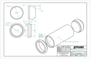
The seal I needed to install was a metric 55 I.D. x 72 O.D. x 8 W (2.165 x 2.835 x 0.315 inches). An ideal sleeve would be slightly smaller on the O.D. to assure the sleeve won’t hang up on the edge of the seal housing, and slightly larger on the I.D. for shaft clearance. For my seal, something close to metric 55.5 I.D. x 70 O.D. (2.2 x 2.76 inches) would be perfect. The nearest size commercial pipe or tube that you could modify to make a sleeve of that dimension would have a 3-inch O.D. with a 0.5-inch wall (2-inch I.D.). That’s not a size most people have lying around. A section of 3-inch diameter bar would work, but making a sleeve from solid stock would be a lot of machine work.
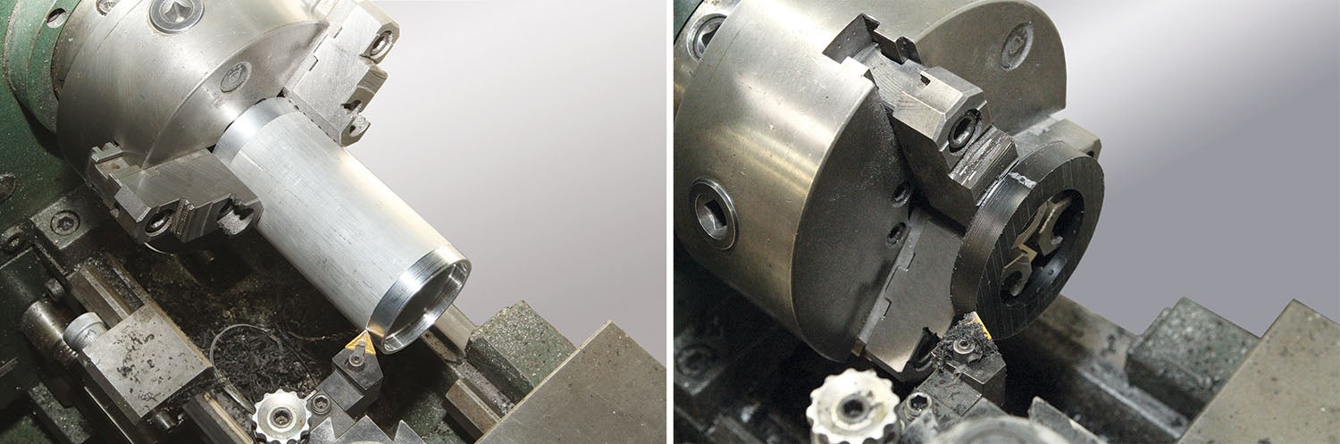
What I did have was some 2.5-inch by 0.125-inch wall aluminum tubing and some scraps of Delrin and nylon plastic. By itself, a tube of that dimension would not be suitable, but by adding the plastic bushings at each end I was able to make an ideal seal press sleeve.
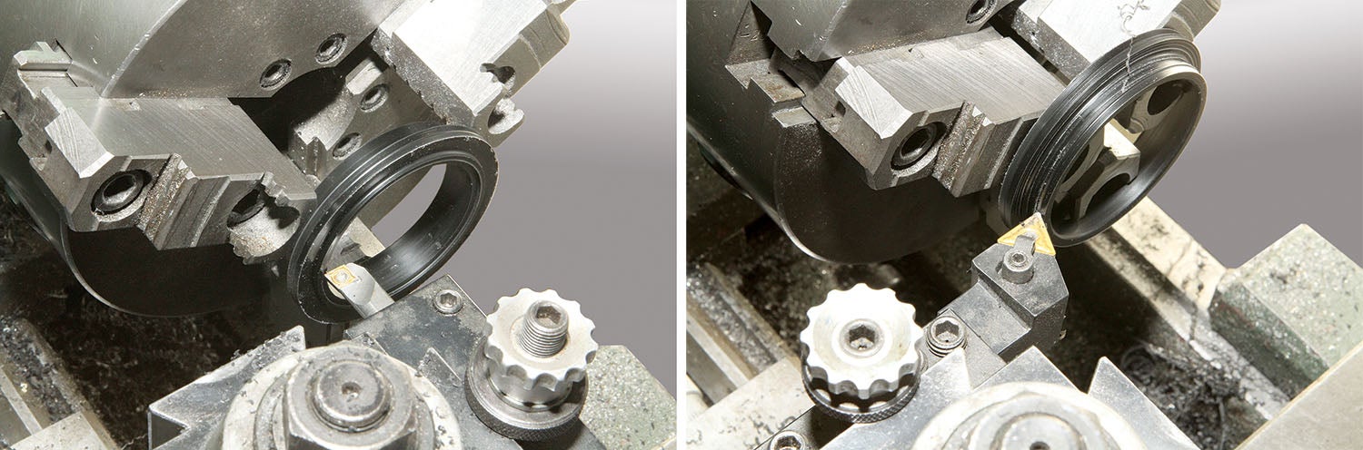
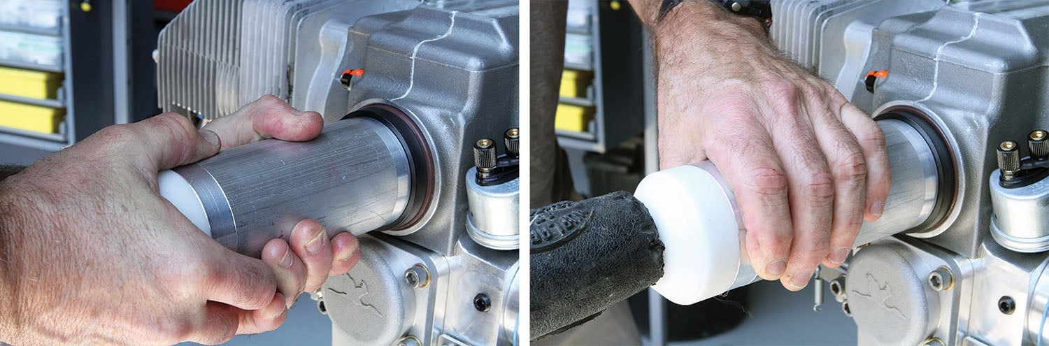
The seal bushing was machined to the face dimensions mentioned above (2.2 x 2.76 inches). A chamfer was added to the I.D. to provide some additional clearance for the seal lip. The bushing I.D. was made to closely fit the prop shaft. The design concentrates all the pressing forces on the outer part of the seal, which is where you want it, and the non-marring characteristics of plastic make for an ideal interface between both the seal and the shaft.
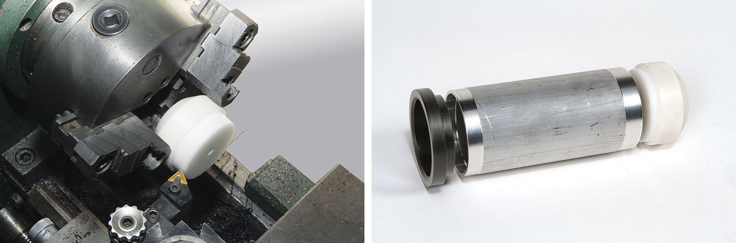
The rear bushing design was simply to create a central face to tap home the seal with a mallet.
Hopefully your flying career is forever free from oil leaks. But if it isn’t, fixing the problem can be a simple matter of getting out in the shop and making a few chips—and custom parts—to fix the problem.
![[Credit: Lisa Turner]](https://www.kitplanes.com/wp-content/uploads/2026/02/Fuel-Selector.jpg?w=218&h=150&crop=1 "Fuel Follies")


