Warning: Do not try this at home!
Propellers are critical flight safety items, and even experienced A&Ps are not allowed to work on certified props unless they are working for a certified propeller repair station. This article is written for educational purposes to show how a typical Experimental constant-speed propeller actually works. It is not intended to show or encourage the reader to work on their own propeller.
 Airplane propellers have been around since the Wright brothers laminated some wood planks together and carved them to shape with a spoke shave. Fixed-pitch wood props were the norm for many years after that until some smart engineer realized that running an airplane with a fixed-pitch prop was like driving a car with a single gear—it works, but not always well. The constant-speed propeller grew out of the desire to maximize both climb and speed capability (not at the same time, of course) and make maximum use of the horsepower provided by the engine.
By allowing the pilot to set the rotational speed of the propeller, the constant-speed prop allows maximum use of the horsepower by maintaining rpm, which is related to horsepower output, while asking the prop to do the most work on the air at slower speeds (climb) and then letting it really “bite” into the air to maximize speed when cruising. The prop does this with the help of the governor, which determines engine speed, compares it to the desired speed, and then varies the oil pressure (in the case of a hydraulic constant-speed prop) that drives the blade pitch from fine (maximum rpm) to coarse (slower rpm due to a larger bite angle for the air).
Most pilots have had this explained to them, at least when they studied for their license exam. Some may not have learned it until getting checked out in a complex aircraft. In any case, while the functionality is explained fairly simply, what actually goes on inside the prop to make this magic happen is usually passed off with a cartoon drawing of the inside of an imaginary prop or with a detailed cutaway drawing of a prop that hasn’t been in production for decades. Since most homebuilders are the type of people who want to know exactly how things work, here is a chance to look at one specific type of constant-speed propeller to see what the parts look like, how they interact, and how a constant-speed prop goes together.
Riding the Whirl Wind
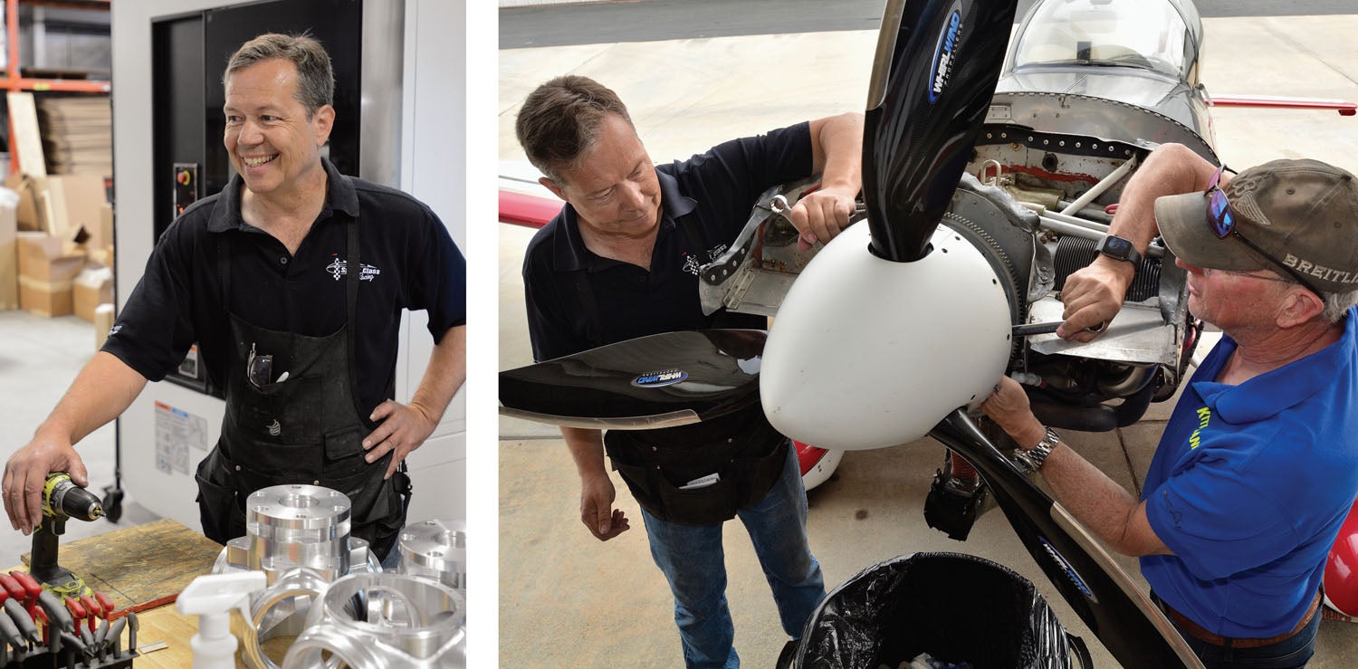
We got our chance to look deep inside the guts of a constant-speed prop when Jim Rust, founder and chief engineer of Whirl Wind Propeller of El Cajon, California, offered to take apart a three-blade Whirl Wind prop with our cameras clicking away. Jim has been building and selling constant-speed props since the mid 1990s and is as busy as ever, supplying new props for a wide variety of homebuilt aircraft. He also builds ground-adjustable props for smaller, lighter aircraft as well as produces custom props for airboats and even wind tunnels. He sells a wide variety of constant-speed props that work well on the current generation of high-performance homebuilts—including his own racing Glasair that is never far from the front in Reno’s Sport Gold class.
Jim began building constant-speed propellers using hubs built by McCauley with his own blade designs. The McCauley hubs are compact and well proven, yet as the years went by, Jim was able to whittle down the parts count and simplify the operations to the point where he now makes all of his own parts, including the hub bodies. As we found out during the disassembly and reassembly process, the internal hub operation has become remarkably simple—and in aviation, simple is often synonymous with reliable. Parts that aren’t there can’t be a problem.
The Basic Components
A constant-speed prop can be broken down into two basic elements—the blades and the hub. Each blade has a root end that attaches to the hub, often called a ferrule. The blade itself may be made of metal, wood or composites (a combination of fiberglass, carbon fiber, resin—and sometimes wood). Blade design is where the engineer shows his aerodynamic skill; there are numerous shapes and airfoils, with a great number of different designs appearing in recent years. But we’re not here to get into an aerodynamic discussion, so let’s look at the other major component—the hub.
Hubs are usually fairly large (by light airplane standards) pieces of aluminum, machined into intricate shapes. Many are split into two pieces, a front and a back. Blades are installed with the case separated, and joining the halves will capture the blades. The Whirl Wind design (based on the McCauley) is a single piece, which provides for a more interesting method of blade retention, which we’ll show you below.
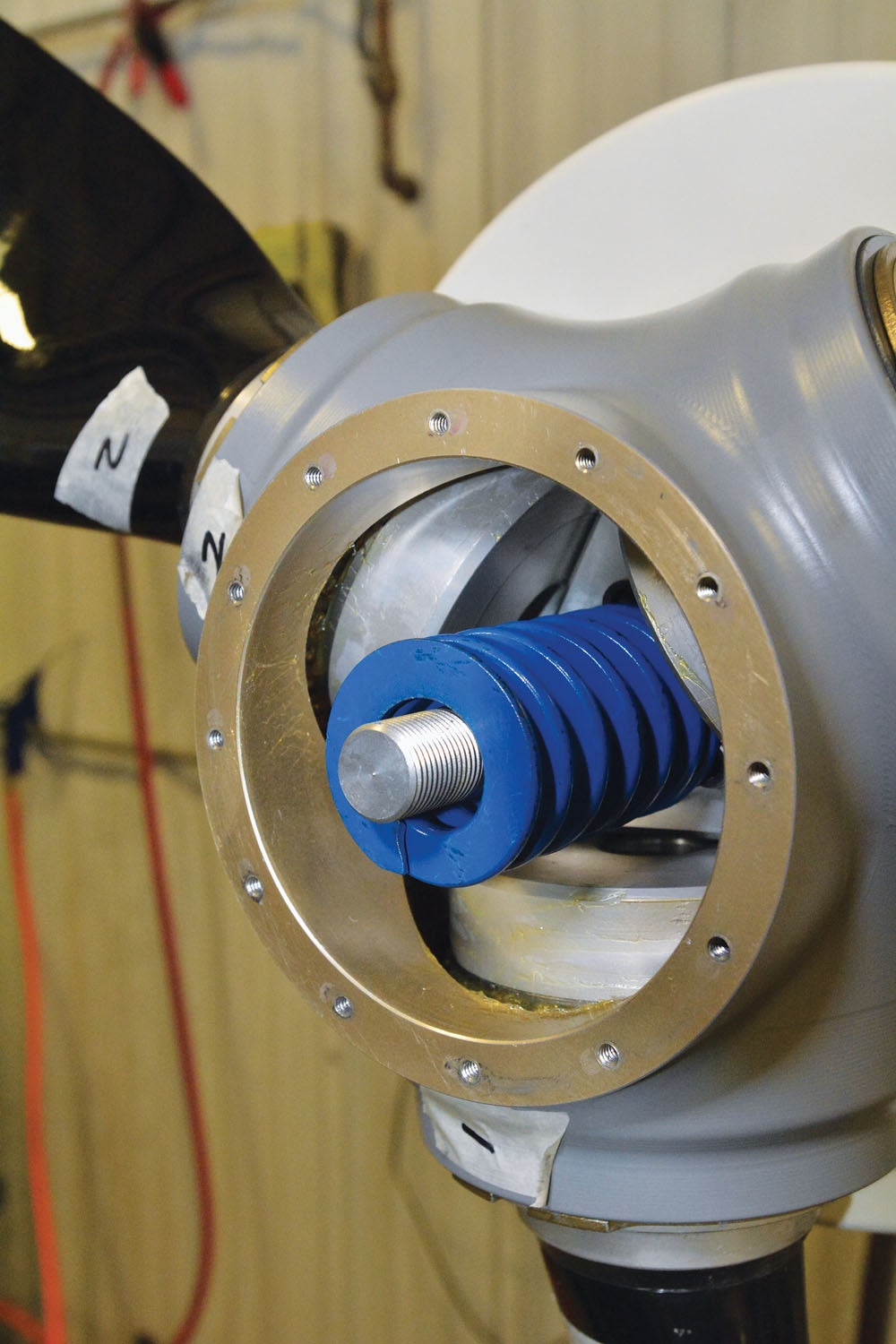
The hub for a hydraulic prop contains a piston, which is pressurized with oil from the prop governor, a spacer bolted to the piston, and a spindle to center the return spring and act as the high pitch stop. As pressure increases, the piston moves forward, moving the spacer forward, which pushes on pins inserted into the prop blades. Since the pins are mounted out on the edge of the hub, pushing them forward twists the blades, thereby changing the pitch of the prop. There is a large spring that pushes the blades back into the starting position when oil pressure is relaxed. There you have the generic description that most pilots learn about constant-speed prop operation—and few learn more. But let’s delve a bit deeper.
Blade Retention
Every pilot who has given constant-speed propellers much detailed thought probably has one great fear—that of a blade coming out of the hub. The fact is, if a single blade departs at an engine speed much above idle, the resulting imbalance is likely to rip the engine right off of its mounts. Without an engine, an airplane is suddenly so tail heavy that it is going to be uncontrollable, and a fatal accident is usually the result. Racing planes, operating near the edge of what is possible in terms of strength, usually are required to have a cable that attaches the engine to the airframe. If the primary mount fails, at least the big weight stays attached, providing some chance at controllability.
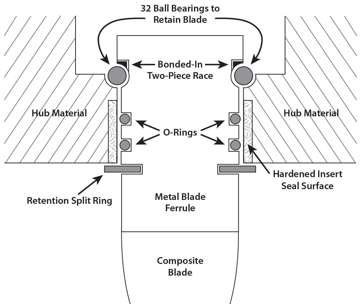
Because of the horrendously bad consequences of a blade loss, the fear of it stays in the back of most pilots’ minds—until they learn how blades are actually attached and retained. The simple fact is that you are far more likely to break a blade than to have one come completely out of the hub. The blades on the prop we are looking at are retained by a race full of ball bearings. The blade ferrule is basically the same diameter as the hole through which it fits in the hub. It has a semi-circular bearing race machined into it at the root end. Once it is inserted, ball bearings are fed into the race through the front of the hub until the ferrule’s race is full of balls. The balls now have half their diameter bearing on the blade, and half on the hub race, effectively making the ferrule too large to slip back out of the hole through which it is inserted.
Once the balls are in place, the blade is pulled outward to put some tension on the ball bearings, and it is held there with a large split ring on the outside of the hub, around the blade. So the blade cannot slide out of the hub due to the ball bearings, and it can’t go further into the hub because of the split ring. Once the engine is running, the blades are held outward by centrifugal force, of course, so the split ring isn’t doing anything in flight—all of the load due to the force from the blade is taken up by the balls.
We asked Jim how many balls could fail (or be missing) before blade retention might be in doubt. Forget about the fact that there is no real way for a ball to disappear—the answer is that if there are one or two balls in place, the blade isn’t coming out. That’s a comforting fact to know, considering there are 32 balls for each blade. When the blade rotates for pitch changes, the balls make that motion smooth and easy—so not only do the balls retain the blade, they are the primary bearing for pitch changes as well.
Pitch Change
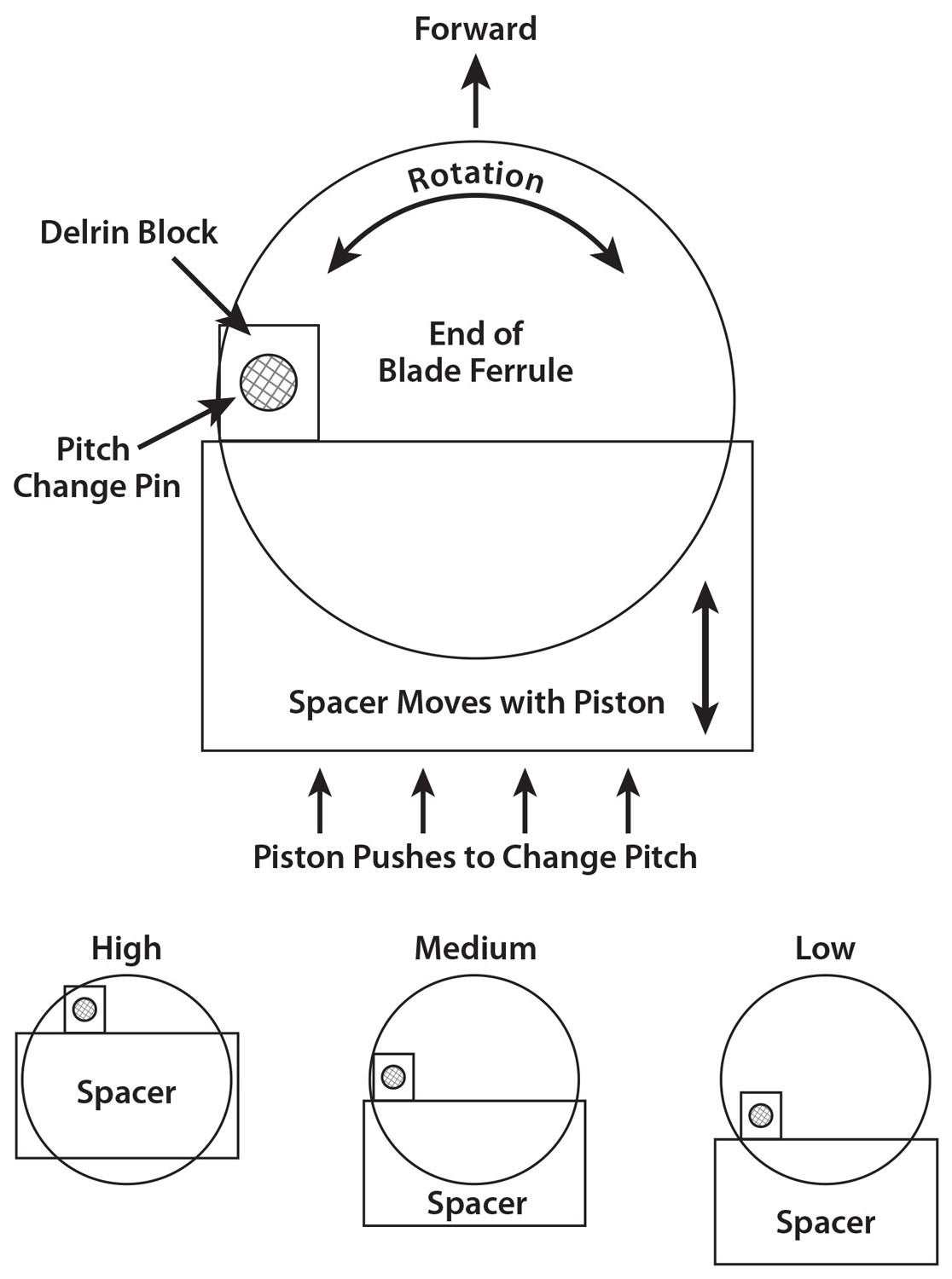
As mentioned earlier, changing the pitch on a hydraulic constant-speed propeller is a matter of changing the pressure input to a piston that drives the pin on the end of the blade ferrule. If you imagine the pin sticking out on the circumference of the circle, and you drive it tangentially to the circle, the circle is going to turn—that is exactly how the pitch changes on the prop.
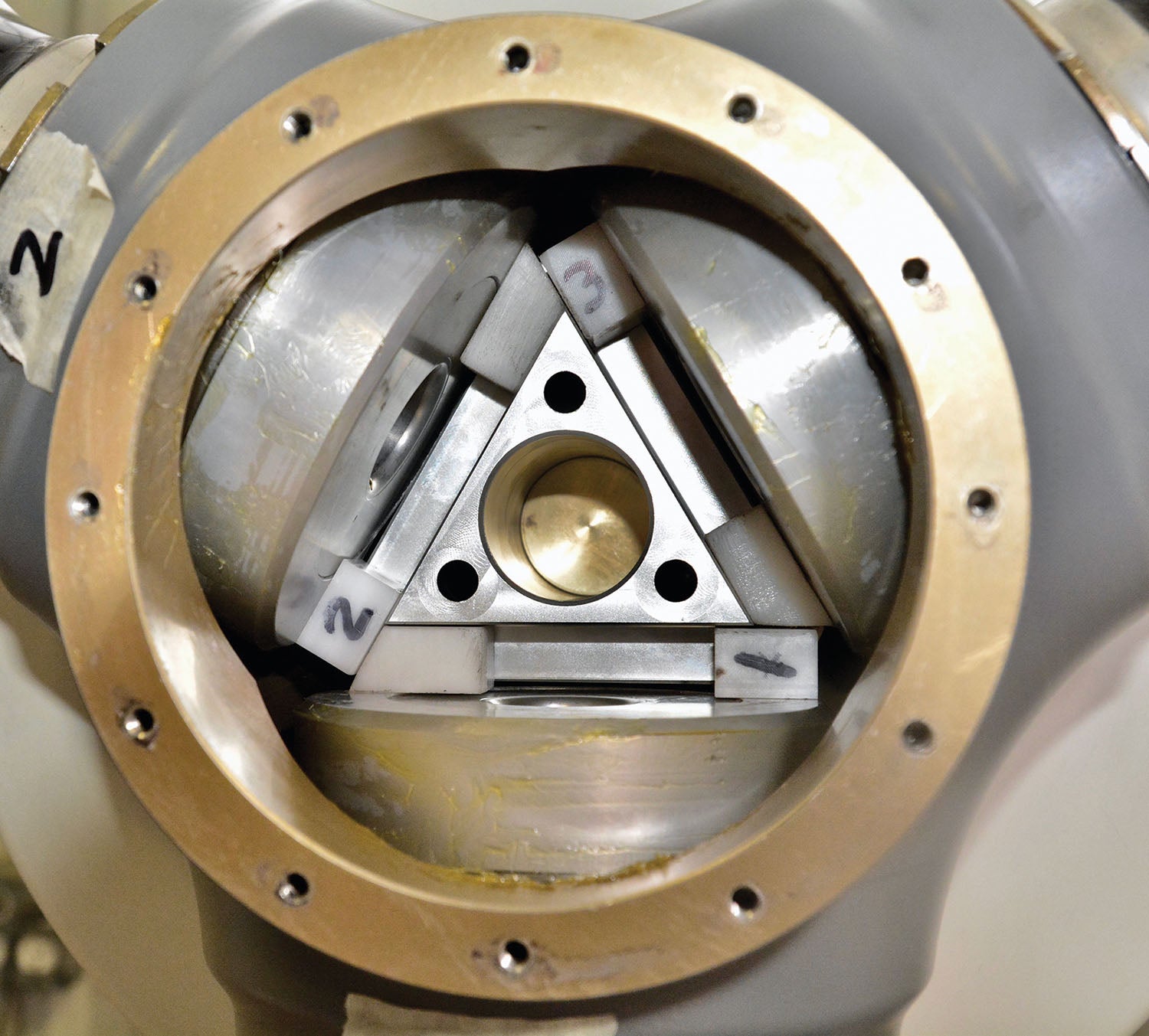
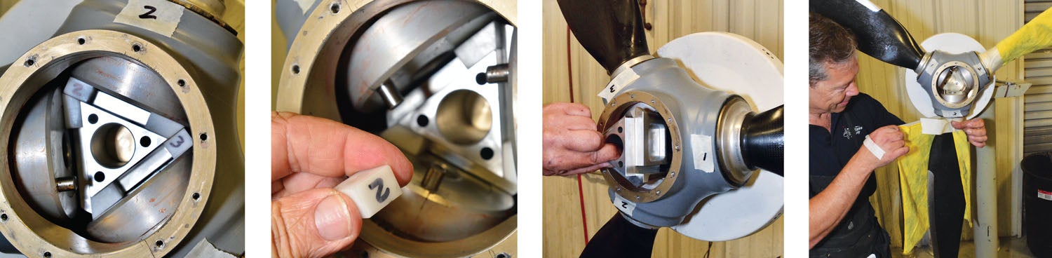
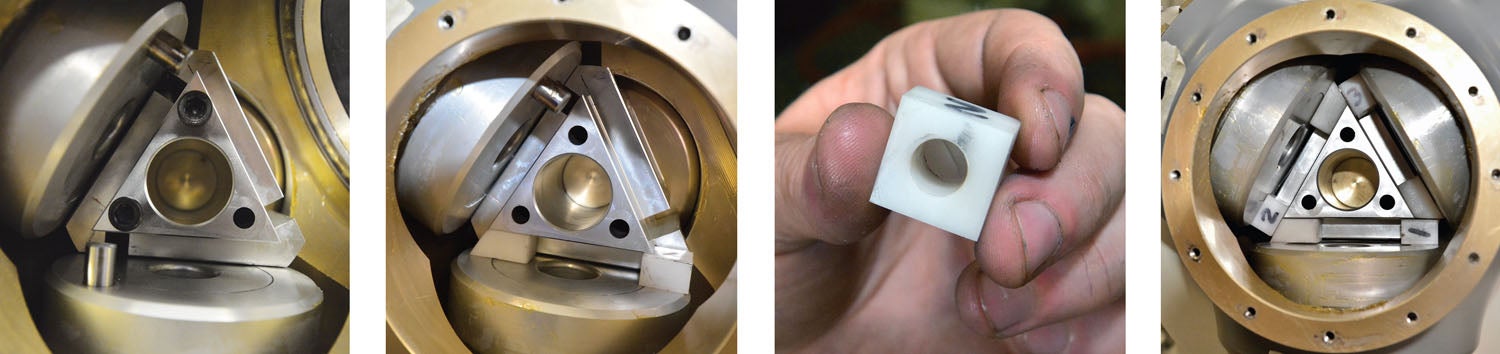
In the three-blade Whirl Wind hub, the piston pushes forward on a triangular spacer. The spacer sits just inside the ends of the three blade ferrules, and each ferrule has a hefty pin sticking out of it. A Delrin block is placed on the pin and rests against the forward face of the spacer. When the piston pushes the spacer forward, the Delrin block is forced forward, carrying the pin with it and thereby changing the blade pitch.
Since the pin is not actually moving in a straight line—it is moving in a curve, and the Delrin block slides along the face of the spacer—the spacer actually has a ledge machined into it, creating a channel for the block. The spacer looks more complicated than it has to be for this simple function—it also has a groove on each face for the pin to slide into. This is used only for assembly, however, to allow the spacer to slide in place past the pins. In operation, the slot doesn’t come into play. In order to make absolutely certain that the pin can’t find its way into the assembly channel in operation, a second Delrin block fits over the channel for each blade, plugging it up.
Bad Vibrations
Anyone who has every tried to assemble precision equipment knows that there are always manufacturing tolerances involved—no two manufactured pieces of anything are ever identical. Yet it is very important that each blade’s pitch at the “fine” stop is exactly the same—so that they will match pitches exactly through the prop’s range of travel. If they don’t match, one blade will always be at a slightly different pitch than the other(s), and uneven lift (or thrust) will result. This is most often felt as a vibration.
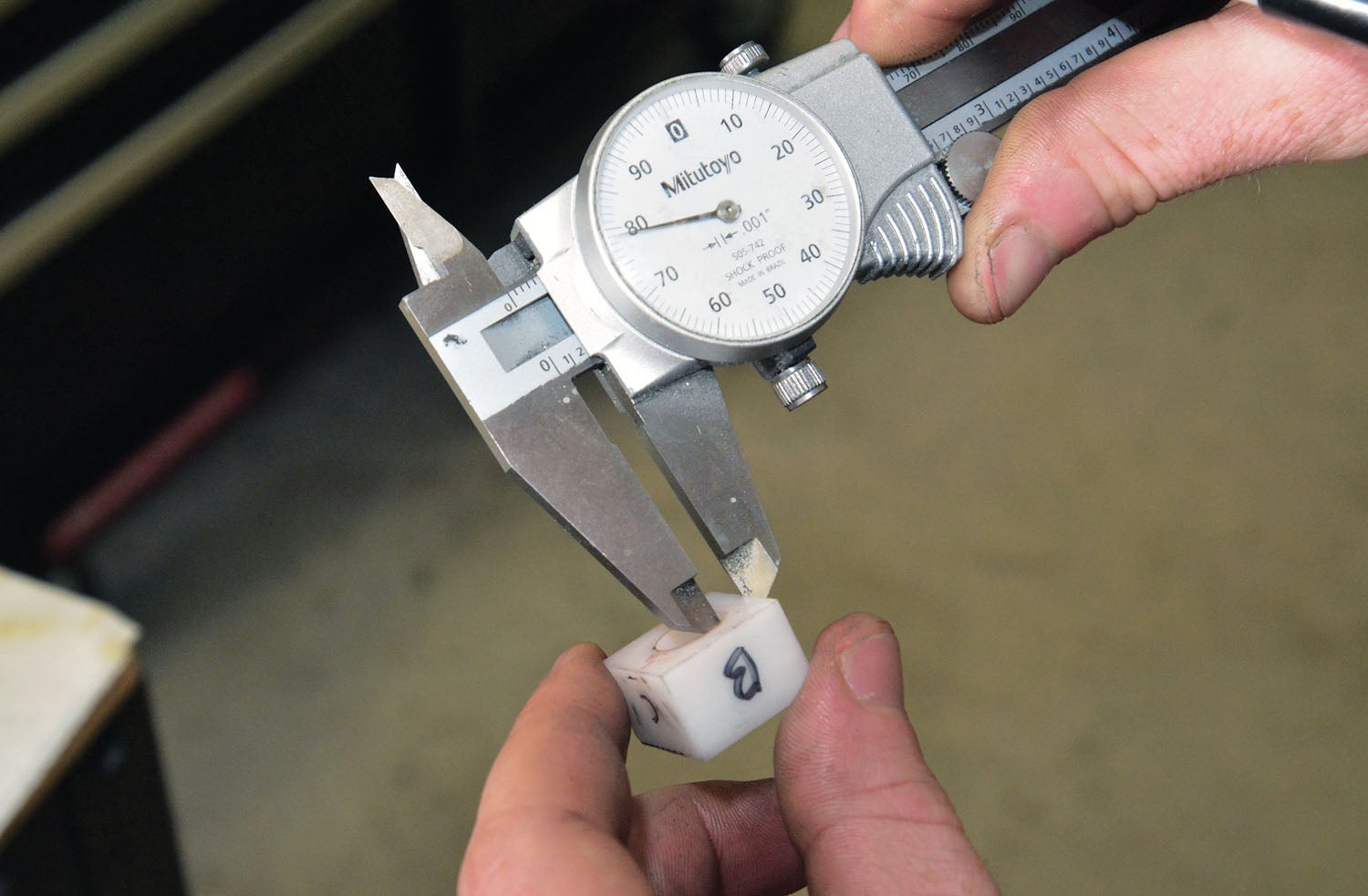
So how do you make sure that all the blades match perfectly? The little Delrin blocks that fit on the hub pins are drilled slightly off-center. Instead of the hole being exactly off center, it is offset so that if you place the block in one of four orientations, it is nominal. In the next position, it is 0.005 inch off. Turn it again, and it is 0.010 inch off, and the fourth face gives you 0.015 inch off. This adjustment range is enough to perfectly match the blades to each other, accounting for the possible range of manufacturing tolerances.
All of this is happening with a simple application of oil pressure on the back side of the piston, the pressure being varied by the prop governor in response to engine rpm changes. How does the governor work to do this? That’s a subject for another article.
Simple is Good
For anyone that has looked at a cutaway drawing of a large constant-speed prop, it might seem astounding how simple these props can actually be. FAA training documents tend toward props fit for DC-3s or Constellations, but that’s not what we are using on our airplanes. Yes, there are more complicated light airplane props—those intended for aerobatic usage that have counterweights for instance. But for the simple task of maintaining a constant engine rpm using engine oil as the working medium, the Whirl Wind is a good example of just how simple things can be.
Low parts count is always a good thing, and while yes, there are 96 ball bearings and 96 little spacers that retain the blades in the hub, they are all identical and easily understood. The parts used to change blade pitch can be counted on the fingers of both hands—and it doesn’t get much simpler than that.
Taking It Apart
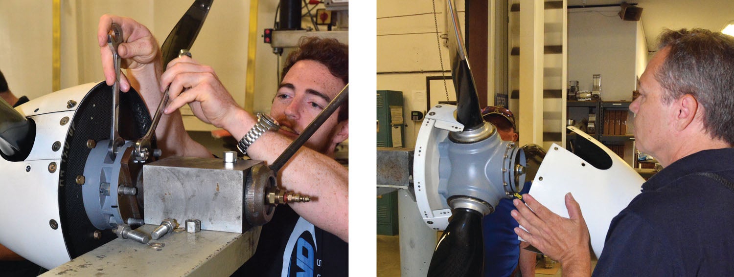
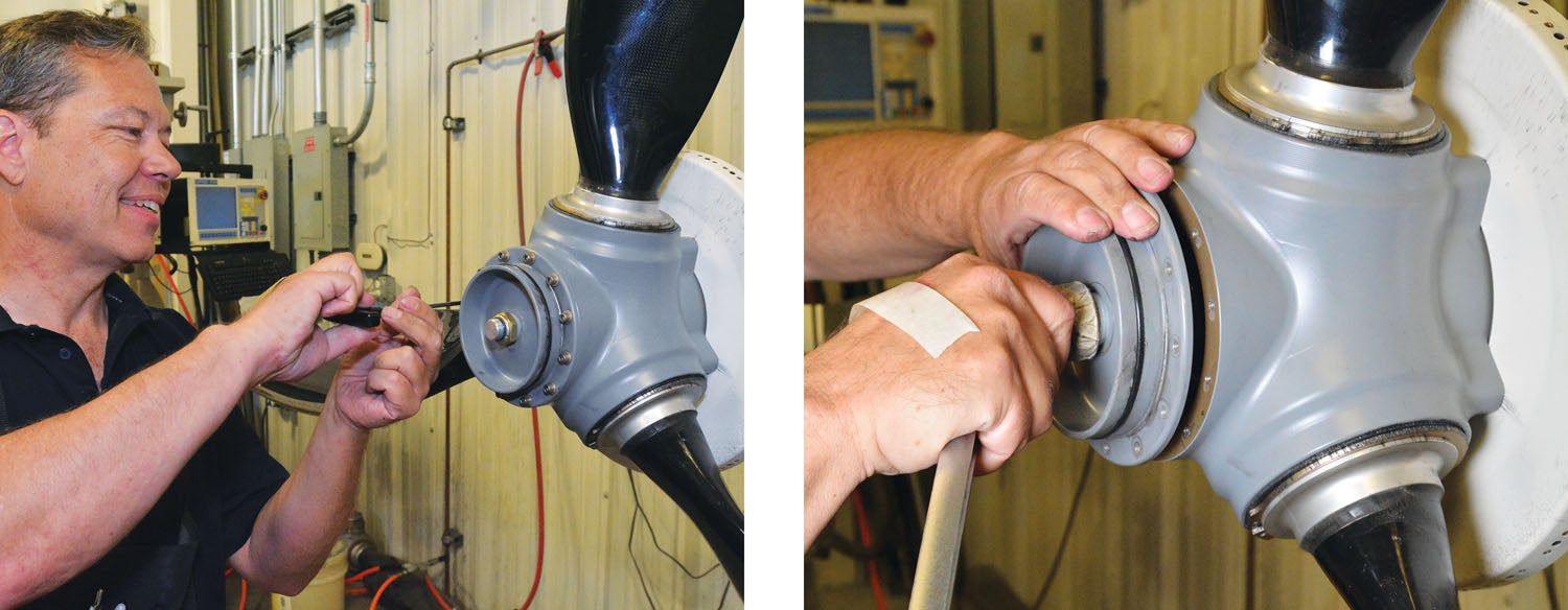
Now that we understand how constant-speed props work, let’s take one apart. The disassembly process for the Whirl Wind 300 series prop is not terribly complicated—because the prop itself is robustly simple. Jim and his assistant, Hunter Hollingshead, mounted the prop on a workstand that allows the prop to be turned to any position or locked down so it won’t turn. There is an air fitting on the back that allows pressurization of the hub. And for those familiar with the fiddling it takes to install the six captive bolts of a constant-speed prop, the workstand has slots with nuts that are easily installed for just two bolts—all that is needed for the work.
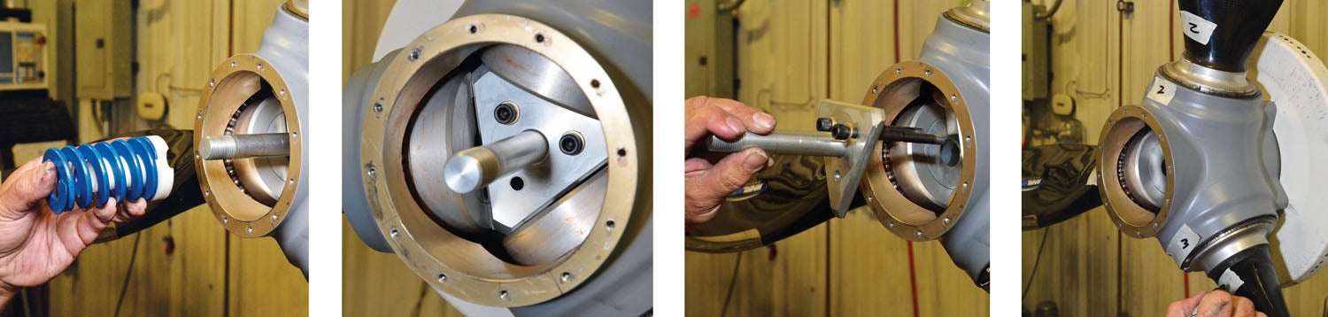

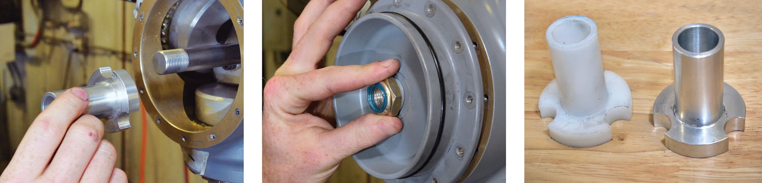
Once the prop is mounted to the stand, the blades and blade ports are numbered (for identification), and the front cover is removed. This involves removing the big nut that acts as the low pitch stop, and a dozen perimeter bolts. This is followed by removing the big spring, spindle and plunger. Next, the blades are manually rotated so that the actuator blocks can be removed, followed by the Delrin blocks that plug the spacer/plunger slots. The blade pins are lined up with the slots, and the plunger comes straight out.
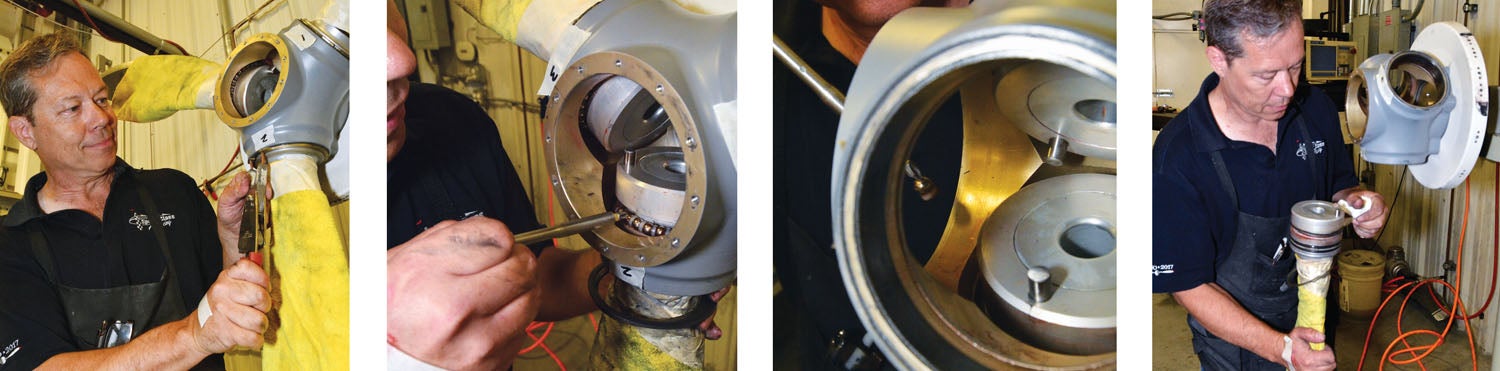
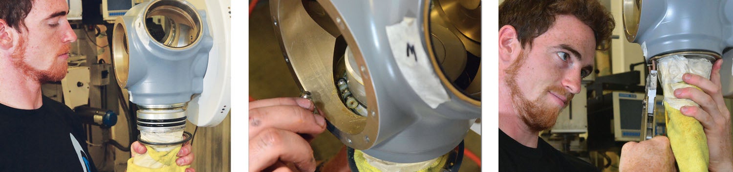
Blade removal is next, and it is the same for all three blades. The blade to be removed is positioned down by rotating the hub, and the hub is locked in position. The large split ring that secures the blade outside the hub is spread with large pin-spreader pliers. This allows the blade to be pushed into the hub sufficiently that the individual ball bearings can be removed. This is done by hand using a magnetic screwdriver. The blade is spun as required to present all the balls, and the nylon spacers between the balls, to the technician.
Once all the balls are removed, the blade simply slides out of the hub—in this case down toward the floor. With the blade ferrule clear of the hub, it can be inspected for wear or fretting and the dual sealing O-rings checked or replaced. The other two blades are removed in the same fashion.
With the blades removed, the only thing left in the hub is a spacer and the piston, which are easily pulled out to be checked.
Putting It Together
Assembling the Whirl Wind 300 is essentially the reverse of taking it apart, with more attention being paid to blade pitch alignment before buttoning it up. Of course, prior to assembly you want to clean everything up. Our prop was being looked at after a fairly low number of hours since its initial build, partly as a check by the factory on a new product, and because they wanted to look at a slightly different method of sealing. That means we expected everything to look like new—and it did.
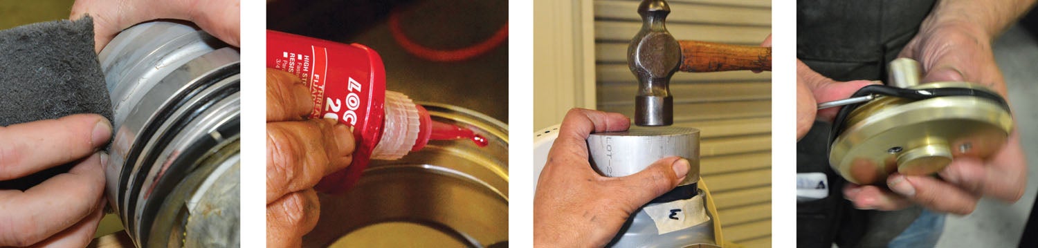
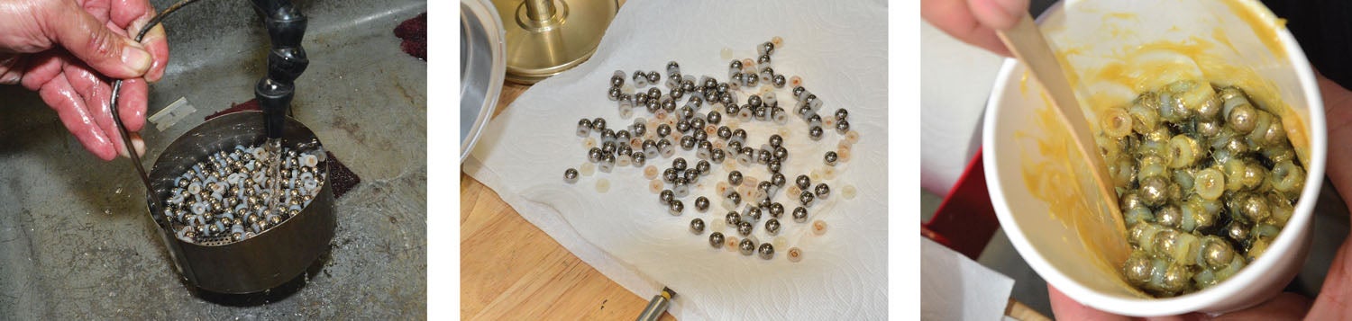
Nevertheless, out came the acetone to remove all traces of old adhesive and sealant from the parts, and everything was looked at carefully. The bearings were cleaned in a solvent parts washer, along with the bearing spacers, then dried on a layer of paper towels.
Because the dual O-rings on the blade ferrules ride in the bore of the hub, the hub is fitted with hardened wear rings in these bores. Believe it or not, rubber O-rings can actually wear away aluminum given enough time, so the rings provide better sealing and longer life. The wear rings are the first thing installed and are sealed using red Loctite on their outside diameter before being pressed into place with a special tool and a light hammer tap.
Next, the piston is put into place using a fresh O-ring and a touch of grease. All O-rings were replaced even though they were low time because, well, O-rings are not that expensive, and the prop was apart! Because the prop is exposed to engine oil, regular petroleum grease is used—the rubber is impervious to it, and it is readily available.
With the piston in place, the blades are installed. First a two-piece bearing insert is glued in place in the groove of the blade ferrule—this is where the loads of the bearings will be reacted. A two-part adhesive is used, and the blades are ready to insert in short order.
Adding a Little Grease
The next step is to put all the ball bearings and spacers in a paper cup. Then a single tongue depressor scoop of special grease is put in the cup and mixed into the bearings with a stick. That is all the grease used in the hub of the prop! The Whirl Wind has no grease fittings and no need for additional grease before overhaul.
Having spent my lifetime pumping six squirts of grease into each side of a Hartzell constant-speed prop hub, I now wonder just how much grease those Hartzell bearings are swimming in. The moral of the story: Use the greasing technique specified by your prop’s manufacturer, but realize that not a lot of grease is required. The grease is there to provide a thin film of lubricant, but remember—the bearings are spinning around and around at engine speeds. They are just reacting the loads due to centrifugal force of the blades and allowing the blades to twist in the hub—and that is a matter of a quarter of a turn one way and back.
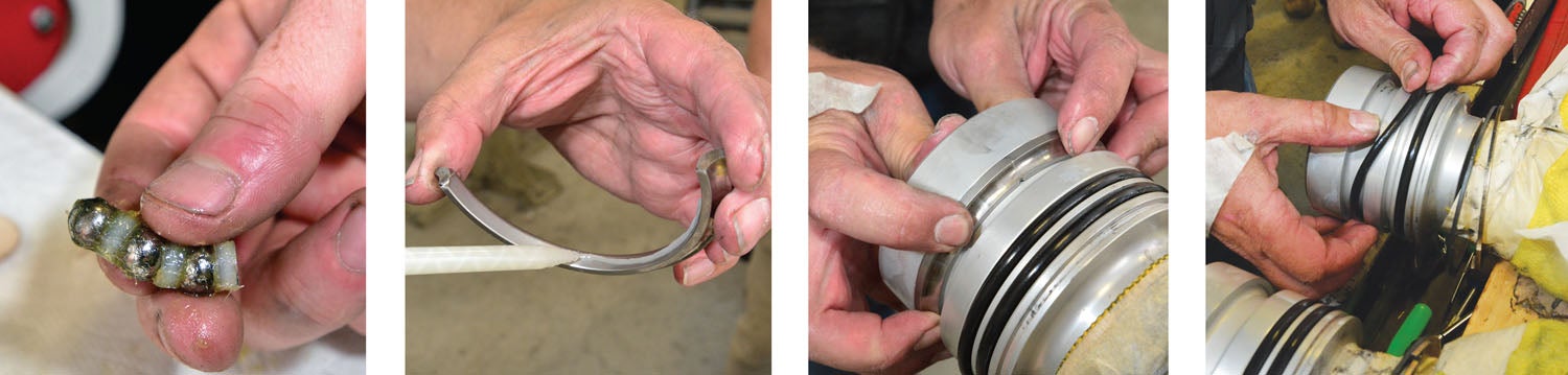
With the bearings full of grease, the blade is slid into the hub from the outside and pushed inward enough to allow the bearings to be dropped into the race. Then it is bearing, spacer, bearing, spacer, bearing, spacer…until all 32 bearings are in place. I asked Hunter if he counts the bearings, or if it is obvious when the race is full, and he said “both.” It is very obvious if one ball is missing, and an extra ball won’t fit.
Once the balls are all in place, the blade is allowed to settle downward under gravity, and the split ring is installed in the groove using the spreader pliers. All new parts make a tight fit, and a few taps with a drift and small hammer helped the ring settle fully into the groove. The process is repeated for all three blades, and all are checked for smooth rotation.
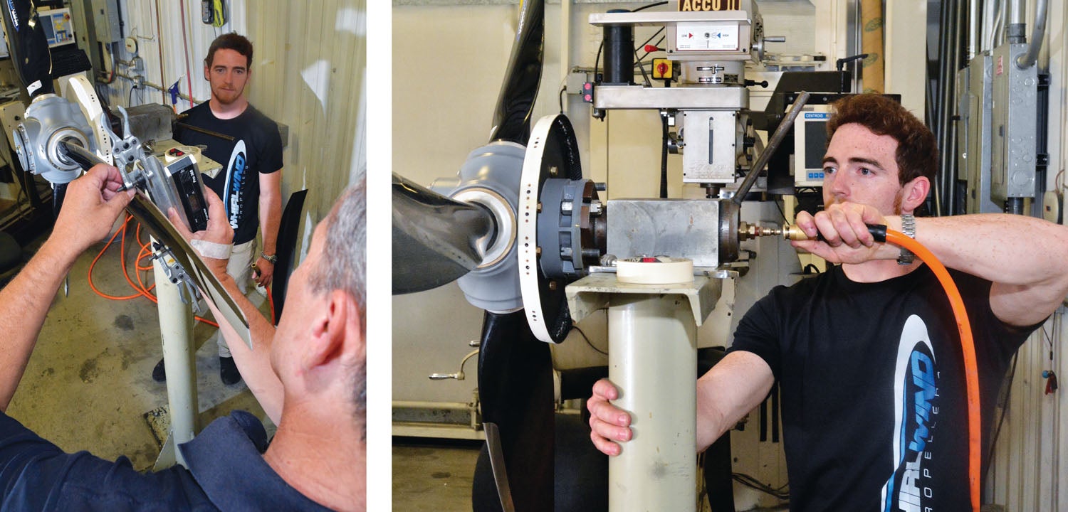
Measuring Blade Pitch
After the blades are fully installed and the internal components of the piston/spacer put in place, the delicate work of measuring the blade pitch begins. Jim uses a jig with V-blocks that slides up the blade from the tip to a predetermined spot that is reached by the spacing between the V-blocks. A digital level is used to check each blade in rotation at the resting (fine pitch) position. Adjustments are then made to the Delrin actuator blocks until all three blades match. When the fiddling is finished, the central rod is installed along with the big spring, and the front cap is bolted in place.
Air is used through the back of the assembly stand to simulate oil pressure—this changes the pitch from fine to coarse. The blade pitch is measured again after actuating the blades several times to make sure they settle into the same spot. At this point, the front cover is put into place, and the big nut is placed on the central shaft to adjust the actual fine pitch stop. Jim measured the blade pitch with his digital level while Hunter turned the nut until the blades reached the appropriate angle (in this case, 15°).
Before the prop is removed from the test stand, Jim goes over the finished assembly, checking to make sure the gaps on the split rings are equal and appropriate, which shows that the rings are closed. He gives each blade a little tug, and the spinner is screwed in place. It’s actually a little easier to do this on the test stand than on the plane, but it works either way. Finally, we unbolted the prop from the stand and headed to the plane—assembly complete!
Understanding exactly what goes on inside the prop hub is probably not essential for the average pilot, especially one who doesn’t maintain their own Experimental craft. But for those who do build and maintain, knowing that the prop is so fundamentally simple inside can help when faced with perplexing problems that you might want to blame on the mysteries inside the hub. Now you can see that there aren’t many things to go wrong—and you can also see that the entire assembly is built to be pretty robust.
At the very least, it is comforting to know that in order for a blade to come out, you’d either have to shatter the hub itself or fracture a whole lot of ball bearings! Simple is good—and a simple prop has fewer things to go wrong.
Photos: Tom Wilson.
![[Credit: Lisa Turner]](https://www.kitplanes.com/wp-content/uploads/2026/02/Fuel-Selector.jpg?w=218&h=150&crop=1 "Fuel Follies")


