A T-tail is a configuration where the horizontal tail is mounted on top of the vertical tail rather than directly to the fuselage. T-tails are frequently used on military transports and also on sailplanes.
Potential Advantages
The primary aerodynamic reason to mount the horizontal tail on top of the fin is to move it out of the wake of the wing. Ideally, the horizontal tail will see less downwash from the wing and may also see a bit higher dynamic pressure since it is clear of any reduction in energy caused by the wing’s passage through the air.
In theory both of these effects could allow the horizontal tail to be smaller and reduce the aerodynamic interference between the wing and the tail.
Another aerodynamic effect of the T-tail configuration is that the horizontal tail can act as an end plate for the vertical tail and increase the lift curve slope of the fin. This can allow the vertical fin to produce more directional stability for the same area and may allow the fin to be slightly smaller to provide the same directional stability as a conventional fin.
If the vertical tail is swept back, the sweep will move the tip of the fin, and hence the horizontal tail, aft relative to the aft end of the fuselage itself. This increases the tail arm and thus the stabilizing effect of the horizontal tail.
Disadvantages
A T-tail is more complex both structurally and mechanically than a conventional tail. The pitch control linkages will be more complex since it is necessary to run the controls up inside the vertical fin to get to the horizontal tail and actuate the elevator.
There are also multiple structural issues. The first is that the vertical tail must withstand the aerodynamic loads generated by the horizontal tail and elevator in addition to the lateral force generated by the fin itself. The end-plating effect of the horizontal tail also shifts the centroid of the side force the fin develops upward, which increases the bending moment on the fin.
A second structural concern is aeroelastic. The horizontal tail has a large yaw inertia. Mounting it on top of the fin means that the yaw inertia of the horizontal tail dominates the torsional modes of the fin. This drives down the natural torsional frequency of the tail and makes it more flutter-prone. The fin must have higher torsional stiffness to prevent flutter.
The combination of the added loads on the vertical fin and the need for much higher torsional stiffness means that the structure of the T-tail will be significantly heavier than the structure of a conventional tail.
Aerodynamic Concerns
Single-Engine Nosewheel Liftoff
On a single-engine tractor-propeller airplane, the T-tail configuration moves the tail and elevators above the slipstream of the propeller in addition to moving them out of the wing wake. This can be a problem on takeoff since the elevators don’t have the benefit of prop slipstream to help them lift the nosewheel off the runway to rotate for takeoff. This has proven to be an issue on several production airplanes with T-tails that ended up with longer takeoff distances because the airplane had to be rolling faster before the pilot could rotate the nose up for takeoff.
Junction
From a structural design viewpoint, it would be ideal to have the main spar of the vertical fin intersect the main spar of the horizontal tail directly. This ideal structural design produces an aerodynamic interference problem: The spars of the surfaces are normally located at or near the maximum thickness point on the chord. The problem is that an intersection between two airfoils with the maximum thicknesses in the same position is likely to experience flow separation aft of the maximum thickness points as the skin of both airfoils pulls away from the airflow simultaneously.
This problem can be reduced by staggering the maximum thickness points of the fin and horizontal tail fore and aft, but to do this requires additional structure to connect the spars of the two surfaces together.
Many T-tailed airplanes have some sort of junction body or fairing at the intersection between the fin and horizontal tail to smooth the airflow over the junction and fair any additional structure needed to connect the fin and the horizontal tail.
High AOA
T-tail configurations sometimes suffer from significant nonlinearity in pitch characteristics with changes in angle of attack.
At low angles of attack, the wing downwash is relatively low and the horizontal tail is above the majority of the downwash. As angle of attack increases, two things happen. The downwash angle in the wake behind the wing increases, and the horizontal tail moves down relative to the oncoming flow, into the downwash behind the wing.
The increased downwash produces a negative angle of attack increment on the horizontal tail. This negative angle of attack change on the tail produces a nose-up pitching moment increment. The result of this is that the airplane loses pitch stability as angle of attack increases.
How severe this effect is depends greatly on the details of the airplane’s geometry. Some T-tailed jet airliner designs have had severe issues with this phenomenon. The British BAC Trident had a fatal accident during flight testing when the pitch-up caused by the T-tail placed the airplane into an unrecoverable deep stall. The horizontal tail on the original DC-9 was enlarged significantly from its initial size before the airplane first flew because Douglas designers were concerned that the DC-9 might be vulnerable to the same sort of problem.
In Practice
In general, T-tails have not proven to give any meaningful advantage for typical single-engine light airplanes. There are some successful T-tailed light airplanes, but there is no strong evidence that they have better performance than similar airplanes with conventional tails.
Several production light planes with T-tails had issues with pitch nonlinearity and nosewheel liftoff. One manufacturer, Piper, actually went full circle during the evolution of its product. The original PA-32 Cherokee Six had a conventional low-mounted all-moving horizontal tail. The next iteration, the PA-32RT-300 Lance II, had a T-tail. The Lance then evolved into the PA-32-301 Saratoga, which reverted to the low-mounted tail of the original Cherokee Six.
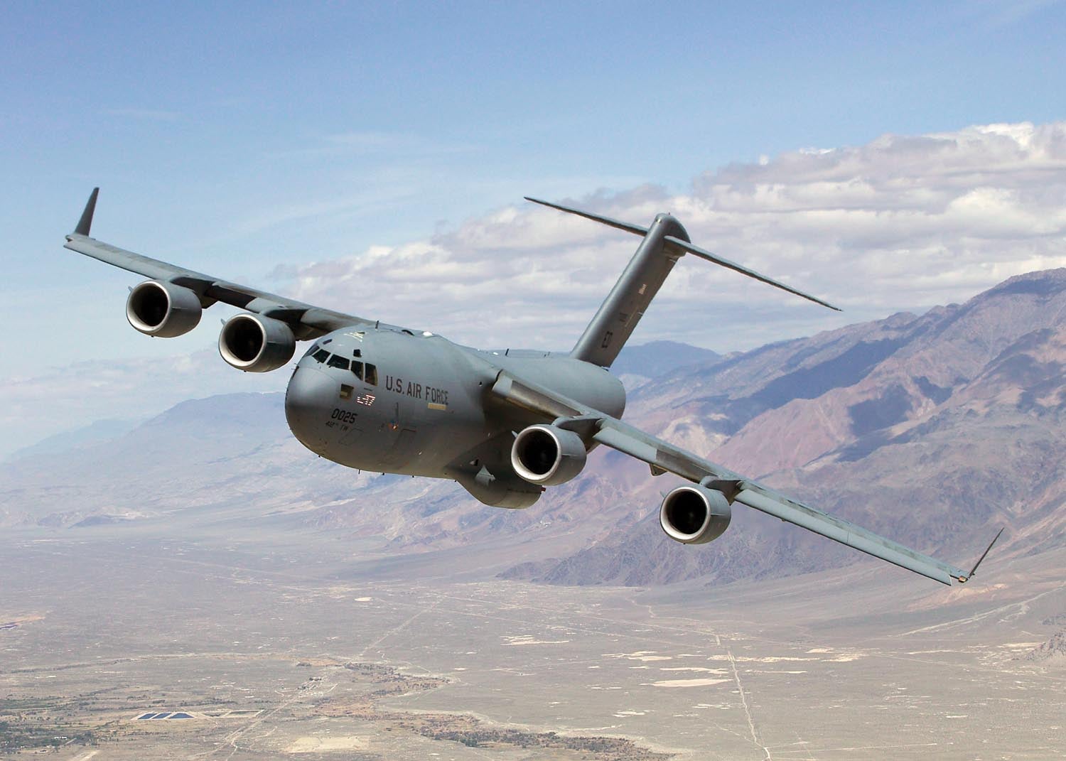
T-tails are used successfully on several military jet transports. The C-141, C-5 and C-17 all have high wings and powerful flaps. They use T-tails to keep the horizontal tail clear of the wakes of the flaps and engines.
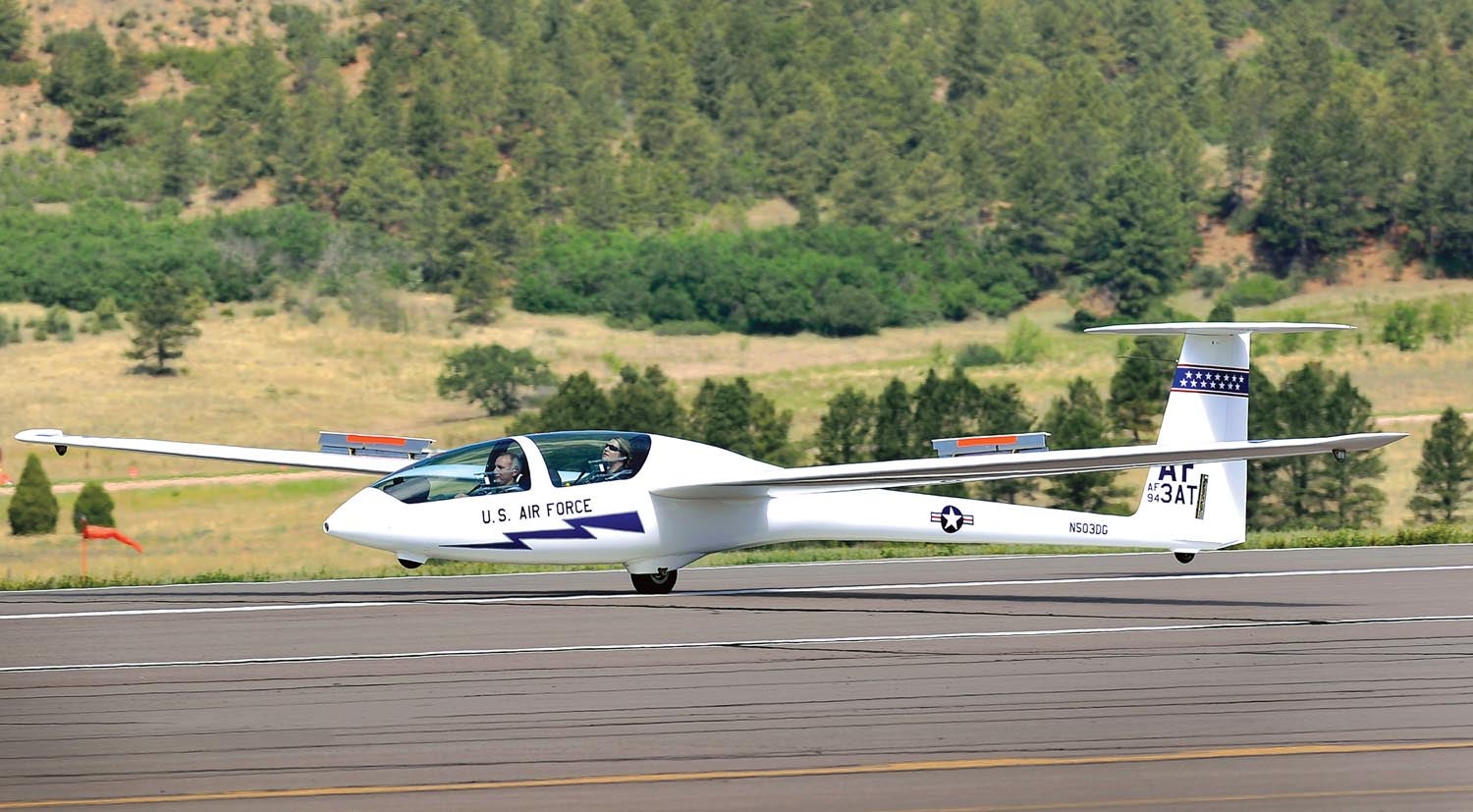
T-tails are also nearly universal on modern high-performance sailplanes. The primary reason for this is more operational than aerodynamic. Sailplanes have a single main wheel landing gear and a tail skid or tailwheel. At rest, one wingtip rests on the ground. The aft fuselage is small in diameter, so a low-mounted horizontal tail would either be very close to the ground or actually touch the ground with the glider in the wing-down resting position. Using a T-tail moves the horizontal tail up enough so that it is safely clear of the ground.


Thanks for that article, Barnaby.
Many years ago I flight tested a Polywagen for a friend. It unfortunately had a plank stabilator with no anti-servo tab.
The first (and only) time I extended the flaps to their full 40 degrees was in level flight, and the horizontal tail stalled violently, pitching the airplane down with hard negative g. Retracting the flaps cured the problem. My initial recommendation was to re-index the flap handle to not allow over 20 deg. flap.
The plane also had other horrible stability problems, which we did a lot of work on. The useful CG range turned out to be only about 0.7 inches.
Thanks for the article! Another reason why sailplanes have T-tails are outlandings. High grass or crops might rip away a conventional tail while a T-tail is high enough for clearance.
Thanks for the saiplane article.
I have a sailplane that in nil/low wind conditions during the aerotow initial run tends to drop the right wing.
Towplane is a Kitfox 4 blade prop and glider a Speed Astir II2B using the recommended longer rope.
Do you have any suggestions to antisipate and correct this effect.
My conclusion is that during the initial run after the wing runner has released, the glider is affected by the slipstream of the tow plane that I believe is a turbulent clockwise flow around the nose of the glider when running straight behind the towplane.
Inputting aileron earlier may help but if too soon, during wing running, may cause the left wing to drop as it is let go.
Any thoughts?
I explicitly use a TTail against the downward on a rear tandem wing with a HZ tail…a 3 wing? Whatever….and when I search for and aft pros and cons about T Tails it seems many simply copy standards….even a university in Germany has a graph regarding that all TTails I found are dangerous, and the have not been at all on many well know airplanes….according to contradicting sources basically all can happen….but then tandem wings, which have been tested recently to exhaustion would all Planken each other out with negative stagger and they don,t either! So I really approachable your elaborate explanations! Thanks! At the end I will build a model and test it to death, no matter if I fight stupid drone rules when doing so….thanks!
So the conclusion I found was:small single engine prop driven airplanes keep the slip stream over the T tail too, at high AoA, so the deep stall should stay far far out of reach, …second : DON,T EVER TRY TO STALL IT AT THE FIRST PLACE, WHEN YOU WANT TO TRAIN STALL GAMES THEN A T TAIL IS THE WRONG BIRD FOR YOU ! there should not be any reason besides intentional Stall training, which has become so very loved today, to ever stall the airplane anyways! …or build your own FacetMobile or Arup Derivate! …kkkk
Comments are closed.