The cooling air inlet serves two functions: First, and most important, the inlet must ingest enough air to properly cool the engine and accessories over the entire range of airspeed and power settings at which the airplane will fly. Secondly, the inlet should be designed to ingest the cooling air efficiently and minimize the drag penalty due to cooling flow. To do this the inlet should manage the airflow in a way that preserves the energy in the cooling airflow and disturbs the external flow over the airplane as little as possible.
Energy and Momentum
Energy in the air can take two forms: the kinetic energy of the velocity of the air and potential energy in the form of air pressure. The law of conservation of energy tells us that kinetic energy can be converted to potential energy (pressure) and back again with no loss of total energy.
An ideal cooling system would take air aboard the airplane, use it to absorb the waste heat from the engine and then return the air to the outer airstream flowing straight aft at the same speed as the airplane is flying.
In that perfect system, the momentum of the air that flows through the cooling system would be the same when it leaves the airplane at it was in the free stream ahead of the airplane before it went into the inlet. In the real world, a zero-loss system is not possible. However, the goal when designing the cooling flow path is to get as close to this as possible.
Even in a very well-designed system, the momentum of the air changes as it flows through the cooling system. From a drag point of view, what matters is the momentum of the incoming air versus the momentum of the air as it leaves the airplane.
This month our subject is inlets, so let’s take a look at how inlet design affects the cooling air and the external flow over the airplane.
Ram Drag
The cooling air flows in through the inlet and comes to rest, or nearly so, relative to the airplane inside the cowling. The rearward-directed momentum of the incoming air is transferred to the airplane and removed from the outer airstream. This momentum transfer causes a (drag) force opposing the forward motion of the airplane. The drag caused by taking the air on board is called ram drag.
Ram drag is an inevitable penalty of bringing cooling air on board the airplane. The first step to minimizing ram drag is to design the cooling system to use as little total cooling air as possible.
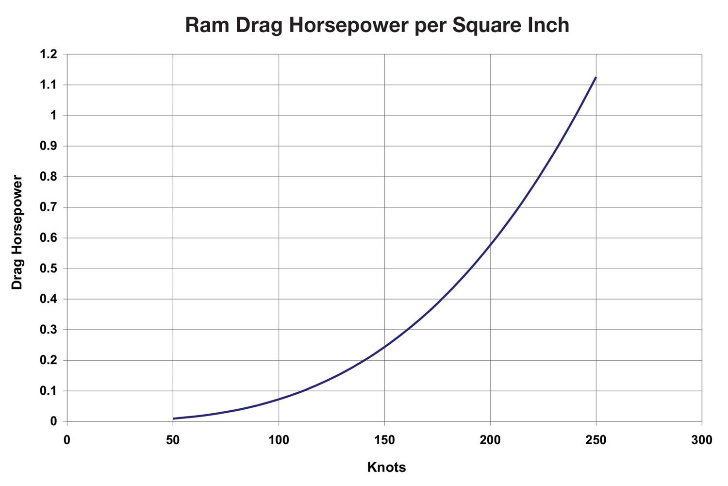
Figure 1 shows the power required to overcome the ram drag of air flowing through 1 square inch of inlet as a function of airspeed. Notice first that the effect is nonlinear. The faster the airplane is flying, the more rapidly the power penalty of a given amount of inlet rises for each additional knot. For example, the penalty for a square inch of inlet at 200 knots is about six times what it is at 100 knots.
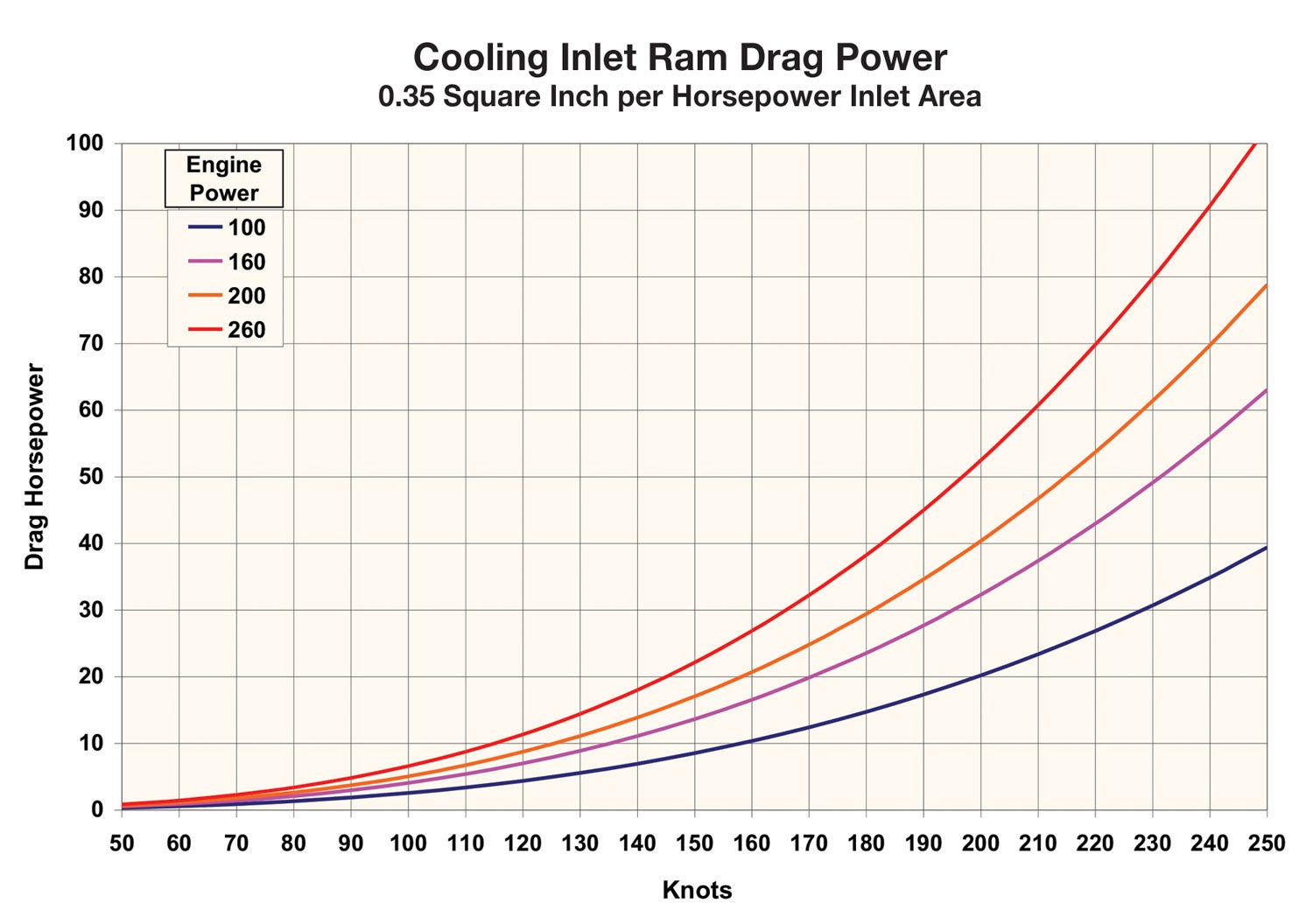
Figure 2 shows the ram drag penalty for the cooling air for engines of several horsepower ratings as a function of airspeed. This figure was derived for a fixed-geometry inlet sized to provide adequate cooling air over the entire flight envelope. It does not take into account the beneficial effect of variable geometry to control the amount of cooling airflow. This figure illustrates how much of the engine’s power the ram drag to cool it can absorb. For example, the ram drag of the cooling air for this system absorbs about 20% of the engine’s rated power at 200 knots.
The potential magnitude of the ram drag as shown by Figure 2 emphasizes how important it is to properly size the inlets to only ingest the minimum amount of air required to properly cool the engine.
The second key to minimizing total cooling system drag is to recover as much of the kinetic energy in the cooling air as possible in the form of pressure within the cowling. This high pressure will help force the cooling air through the fins on the cylinders. It can also be used to eject it backward through the cooling outlets to recover some of the drag caused by ram drag.
Figures 1 and 2 show the importance of preserving the energy in the cooling airflow as it moves through the cooling system so that there is enough energy in the flow to recover some of the ram drag by ejecting the cooling air aft through the outlets.
Inlet Pressure Recovery
The cooling air starts upstream of the airplane, flowing at free-stream velocity and ambient static pressure. As air moves into the cowling via the inlets, it is slowed down and some of the energy of the flow is converted from kinetic energy to potential energy in the form of increased air pressure.
An ideal inlet system takes the air on board and slows it down without losing energy to flow separation and turbulence. If the flow separates and becomes turbulent, some of the kinetic energy of the flow is converted to heat and the momentum in the air is lost. This leaves less kinetic energy to be converted to pressure.
A real-world inlet system should preserve the energy in the airstream as much as possible. The inlet and duct behind it should slow the air down and increase its pressure without flow, separation or turbulence that dissipates energy.
If there is enough room behind the inlet throat, a diffusing duct that expands the cross section as it goes downstream can provide very efficient pressure recovery. In practice, this is difficult to do because on a typical tractor engine installation there is not enough distance between the back face of the propeller and the cylinders to install a diverging diffuser duct that can expand the flow without having some flow separation.
There are two approaches to dealing with this. The first is to design the inlet lips and ductwork to do as well as possible given the length available. An inlet and diffuser that partially expand the flow without separation is much better than a system that has flow separation right downstream of the inlet throat.
The second approach, which can have large benefits, is to place the inlets properly. An effective way to improve the situation is to locate the inlets in natural high-pressure, low free-stream velocity areas of the flow. This minimizes the amount of diffusion needed to recover the ram pressure in the air in a spot on the surface of the airplane where the airflow has already been slowed and compressed by the natural flow pattern over the shape of the airplane.
Ideally, the inlet should be at or near what is called the stagnation point. The stagnation point is a spot where the external airflow is arriving at 90° to the surface and will naturally be brought to rest at that point. At the stagnation point the air is already compressed to its ideal static pressure, so placing an inlet there requires very little diffusion downstream to get good total pressure recovery.
Conversely, placing inlets where the external air is flowing fast and at low pressure makes the design of the inlet much harder and makes it difficult to get good inlet pressure recovery.
Next month we will take a look at how to find the proper place for cooling inlets and how the shape of the inlet lips themselves affects the cooling flow.


Good article Barnaby….looking forward to hearing more and to getting some calculated!
Lkeddie
Good teaser to an important subject. I too am looking forward to more. I am particularly interested in the pressure dynamics as the cooling air circulates through the cylinders and through the outlet. My Glasair II system with IO-360 is resulting in very high CHTs even when my baffles, timing, etc., are per specs. I would like to know how vents or cowl flaps affects this dynamic.
Looking forward to next month and hopefully example cowlings. I am tooling up to build a custom nose bowl and need this information so that the design will be successful.
Comments are closed.