As we saw last month, an ideal cooling air inlet system should ingest air from the free stream and bring it to rest or very low speed without flow separation or turbulence that dissipates the energy of the flow. The kinetic energy of the cooling air from the outside flow should be converted to potential energy in the form of increased air pressure inside the cowling. Any flow separation or turbulence dissipates some of the kinetic energy, converting it to a slight heating of the air.
Internal Flow
As the cooling air is ingested, it flows over the lip of the inlet. The air will rarely be flowing exactly normal to the plane of the inlet. The inner portion of the inlet lip must be able to turn the incoming flow downstream into the inlet without stalling.
The direction the airflow arrives at the inlet lip varies with flight condition. At high mass flow and low airspeed, the streamlines will be moving inward at the lip and will need to turn downstream around the lip into the throat.
Lower mass flow and higher airspeed causes the inlet to spill as some of the air approaching the inlet orifice does not go into the inlet but flows around it instead. The streamlines will be curved outboard at the lip as the spilled airflow turns to flow around the inlet.
A sharp-edged inlet will experience flow separation unless the sharp edge is aimed exactly into the incident airflow. It’s not possible to aim a fixed-geometry sharp inlet lip in multiple directions.
This means that the lip of the inlet should be rounded rather than sharp so the air can flow smoothly around the lip as the incident angle of the flow varies with flight condition.
External Flow
It’s important to keep the flow clean and attached on the inside of the inlet to minimize turbulence and loss of energy of the cooling air entering the cowling.
It’s equally important to ensure that the air that does not go down the inlet and spills around the lip remains attached to the exterior of the cowling and maintains clean airflow over the exterior of the airplane. The inlet lips should guide the spilled air smoothly around the inlet so that it flows cleanly downstream over the skin of the airplane. If the air were to separate from the inlet lip, the turbulent, low-energy air would propagate downstream and adversely affect the flow over the airplane behind the inlet.
The angle of incidence at which the air arrives at the inlet lip is affected by many factors, including the placement of the inlet. This can make the design of the inlet lips more difficult. In particular, if there is significant cross flow relative to the orientation of the inlet orifice in the external flow, then the lips of the inlet need to turn the flow more. The “upstream” lip must turn the flow into the inlet orifice, and the “downstream” lip must both turn air into the inlet and turn the flow moving across the inlet downstream so that it remains attached to the external skin of the cowling.
Pressure Recovery
Once the air passes through the narrowest portion of the inlet duct (the inlet throat), it should flow into an expanding (diffusing) duct that slows down the flow and increases its pressure. If the inlet lips are properly shaped and there is enough distance downstream of the inlet throat, this can be done with very little loss of energy. Inlets for jet engines are examples of such a system, and a well-designed jet engine inlet system can have total pressure losses of the order of 1%.
The designer of a cooling flow path for a piston engine has a more difficult task than the designer of a jet engine inlet system for two reasons. The first is that the cooling air must be slowed much more than the flow into a jet engine. The second is that on a typical piston engine installation, there is not much room between the back of the propeller and the front of the cylinders in which to place a diffusing duct.
Inlet Position
To recap, for good performance we want an inlet system that has attached flow on the lip so that both the air flowing into the inlet and the air that flows around the inlet and over the skin of the airplane flows smoothly and without turbulence.
The inlet system should also smoothly slow the air that enters the inlet to nearly static and recover as much as possible of the kinetic energy in that air as increased air pressure.
Proper shaping of the inlet lips can help ensure attached flow, but the designer has fewer options available to ensure good pressure recovery because there is not enough room between the inlet throat and the cylinders to incorporate a long enough duct to fully diffuse the inlet flow if it enters the inlet at anything like free-stream velocity.
Fortunately, the performance of the inlet can be greatly improved by locating it properly.
The Stagnation Point
As air flows around an object, it is deflected by the nose to flow over either side. There is one dividing streamline. Air on one side of this dividing line flows in one direction around the object, while air on the other side is deflected in the opposite direction. On a wing, the air above this dividing streamline flows over the top of the wing while the air beneath it flows over the bottom of the wing. The dividing streamline itself intersects the skin of the object at 90°, and the air is locally brought to rest at the point where the dividing streamline (also called the stagnation streamline) meets the skin. This point is called the “stagnation point,” and the air at this point is stationary relative to the skin, but it has also been compressed against the skin so that all of the kinetic energy at this point has been converted to pressure.
Inlet Position
We can take advantage of this natural compression of the outer flow and minimize cross flow across the inlet face by placing the inlet at or near the stagnation point on the cowling.
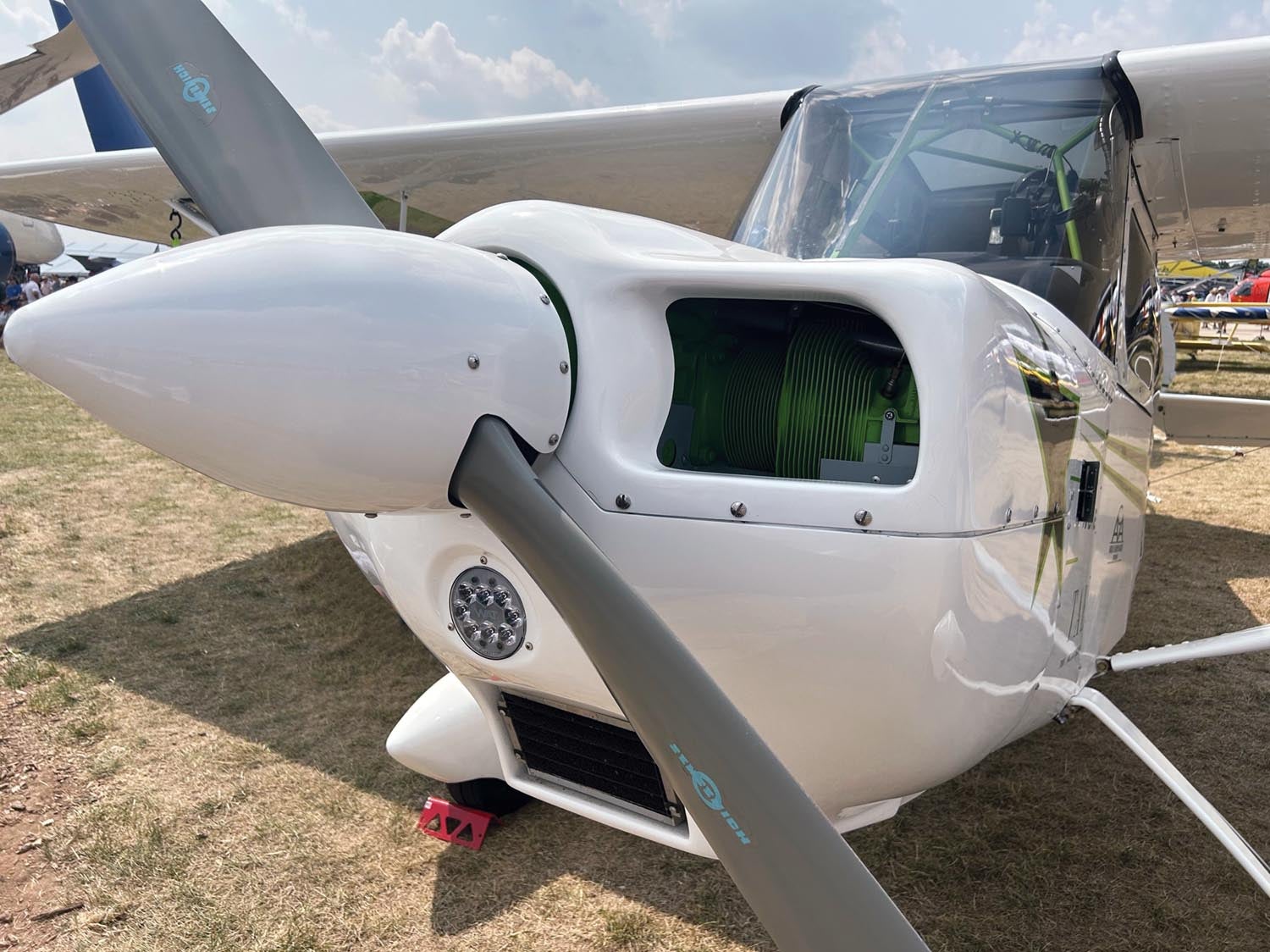
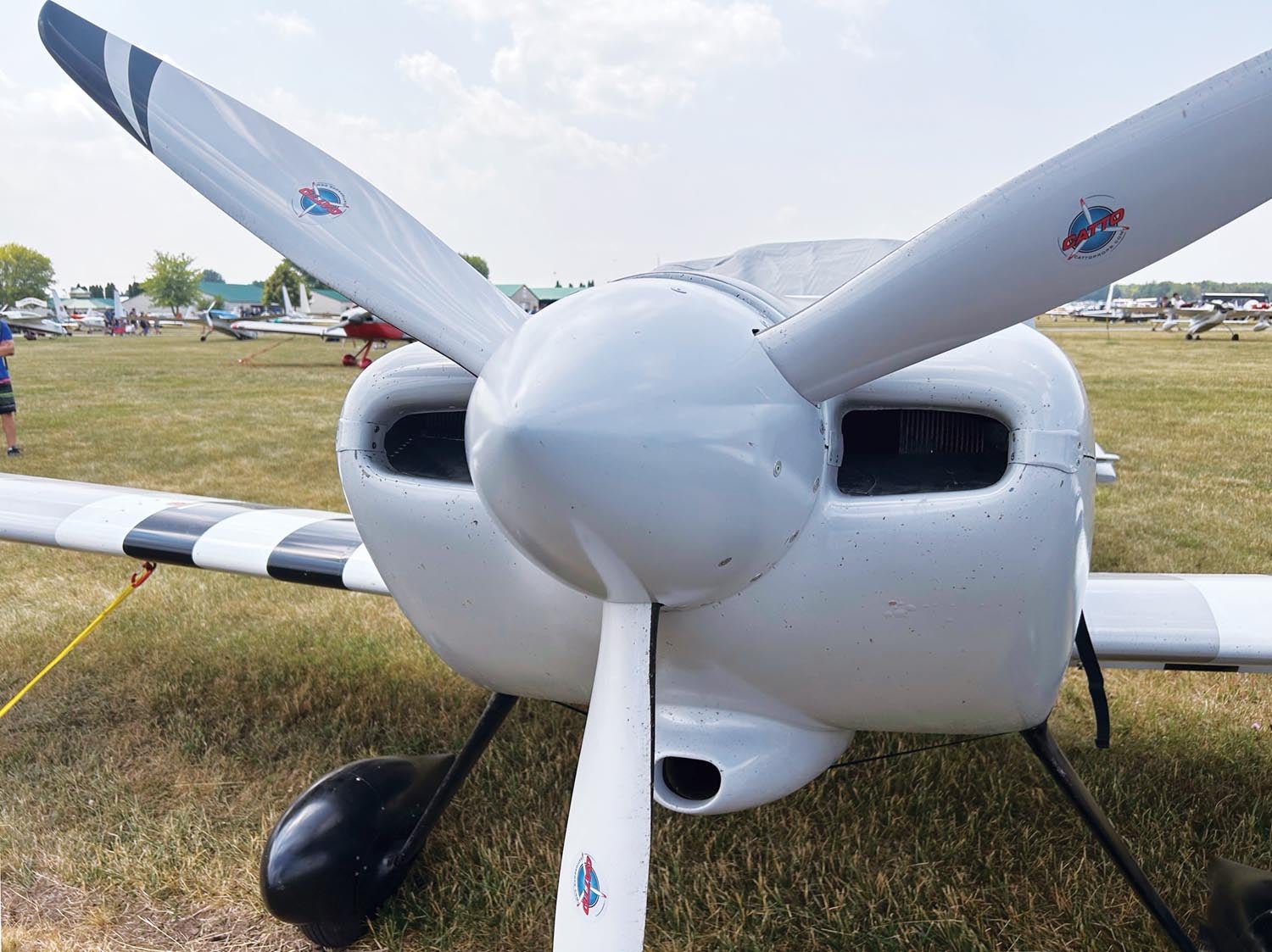
The position of the stagnation point varies some with angle of attack and sideslip angle, but for typical piston-engine cowlings the stagnation point is at, or slightly below, the most forward part of the front face of the cowl. This is where the cooling air inlets should be placed for best performance. There is also a region of high local air pressure just below the spinner, and this is a good location for an induction air inlet or an oil cooler inlet.
It’s also important to avoid placing inlets in areas where the flow is moving fast and the air pressure is low. A particularly poor place to locate an inlet is on the sides of the cowling, particularly in the forward half of the side of the cowling. This is a natural low-pressure zone, and the inlet will have to capture fast-moving air and use the momentum of that fast-moving air to force it down the inlet. There is no easy way to slow the air down efficiently once it passes into the inlet, so a side-mounted inlet is likely to have poor flow and low pressure recovery. In some cases, the external air pressure is low enough that the inlet cannot recover enough ram pressure to drive the air into the duct, and it’s not uncommon to have poorly placed inlets flow backward if they are in a low enough pressure zone.
Next month we will continue downstream with a look at what happens inside the cowling.


Mr Wainfan, concerning the effects of high thrustline on a pusher, could you comment on the option of building in more down thrust to compensate?
I acquired an ultralight Beaver pusher with 80 hp not the original designs 65hp.
Both the builder and the 2nd owner suggested that the nose down effect that prevented normal rotation on takeoff could be compensated for by throttling back. This idea bothered me.
They also suggested it was just too much power.
I have put in 10 degrees of down thrust to compensate. but rarely see this solution in other pushers.Why not?
I’ve been told that there is an ideal ratio between outer and inner radius of an inlet lip. The inner radius can be smaller, but by how much? 0.5? 0.7? Supposedly the formula can be found in a NACA paper, but I can’t find it. I see graphs of shapes called A, B and C but I keep missing the formula.
Comments are closed.