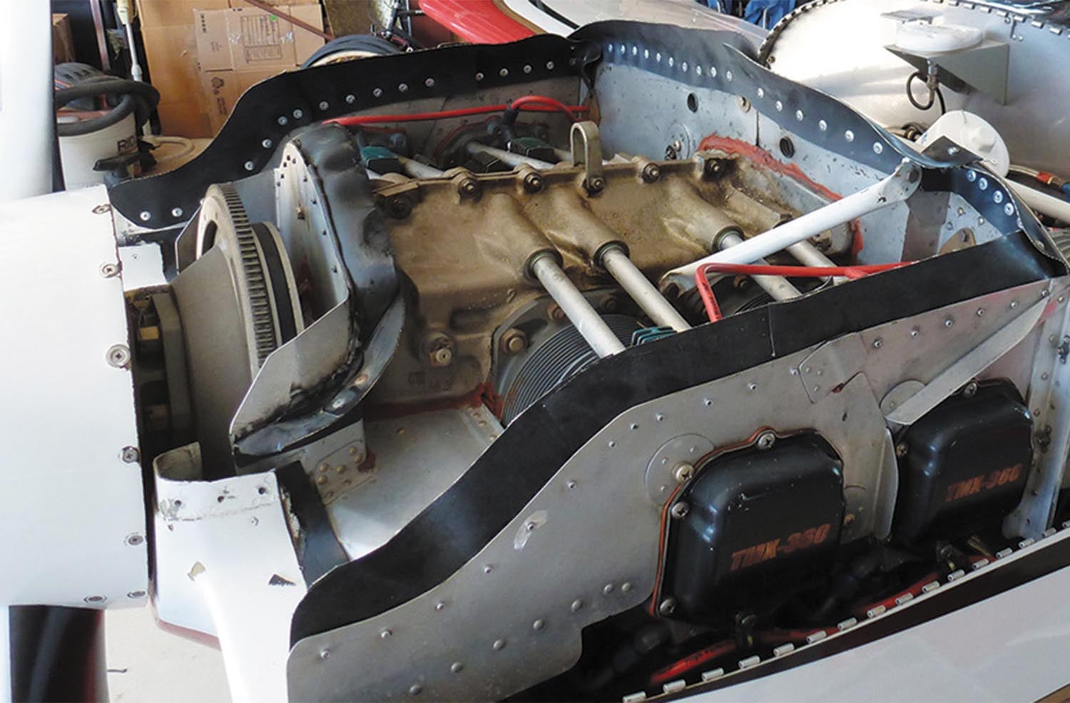
As we saw in last month’s edition of Wind Tunnel, only about one-third of the energy released by burning the fuel in an internal combustion engine is converted to power delivered to the crankshaft. The remaining two-thirds of the energy is waste heat. To stay at a constant safe operating temperature, the engine must reject this excess heat. The waste heat must be transferred from the engine to the surrounding air and carried away from the airplane. Some of the waste heat leaves the engine in the hot exhaust gas. The remainder heats the engine itself.
Cooling the engine and its accessories requires a continuous flow of air to come in from outside the airplane to absorb the heat. Once this cooling air absorbs waste heat from the engine, it must flow overboard to carry the heat away.
There are two primary goals to keep in mind when designing the cooling system for an airplane’s engine: The first and most important goal is to keep the engine cool enough to operate safely and reliably. The second is to minimize the drag penalty of the cooling airflow.
Keeping It Cool
The cooling system must be able to cool the engine effectively over the entire flight envelope of the airplane. This is not as simple as it might first appear. Both the amount of heat that needs to be rejected and the air available to absorb that heat vary dramatically with airspeed, power setting, altitude and air temperature.
The worst case for cooling is a situation of high power and low airspeed, as is the case in climb. At full throttle, the engine is generating maximum heat and needs the most cooling.
Airplane cooling systems operate on ram pressure. There is no fan to pull air into the airplane, so the cooling air is driven into the inlets by the speed of the incoming air. Accordingly, the mass flow of air through the inlet is a direct function of airspeed. Ideally, if there is no blockage that causes spillage, the inlet swallows a stream tube of air that has the same area as the inlet aperture. The mass flow in this stream tube is directly proportional to airspeed. The faster the airplane is flying, the more air the inlet will ingest.
In a maximum-effort climb the airplane is flying slowly, so the amount of cooling air available is at a minimum. This minimum-available cooling air must absorb the maximal amount of heat produced by the engine at full power. This phenomenon leads to the most significant compromise the designer of the cooling system must resolve. This is the choice between a fixed-geometry cooling system or one with some form of variable geometry.
The cooling air system must generate enough cooling flow to cool the engine in the worst-case, full-power, hot-day climb condition. Once the airplane is in cruise, the airspeed is higher and the engine is developing less power than in climb. This means that there is more cooling airflow available and it needs to absorb less heat.
In cruise, a system sized to cool the engine properly in climb will take in more cooling air than necessary to cool the engine. On the other hand, if the system is sized to cool the engine in cruise without taking on excess air, it will not be able to cool the engine adequately in climb.
The faster the airplane is, the more significant the difference in cooling system requirements between climb and cruise becomes. Higher speed not only makes more cooling flow available but also increases the performance penalty of ingesting excess cooling air. It is also possible to get into a situation where at high speed the cooling system ingests so much air that it overcools the engine, causing it to run below its preferred operating temperature.
Fixed-Geometry Cooling
A fixed-geometry system has several advantages. It is very simple and has no moving parts. This makes it the lightest, lowest-cost and most reliable system. Since the system is a fixed part of the airplane, the pilot has no control over it. No pilot action is needed to manage engine cooling.
The disadvantage of a fixed-geometry system is that it must be designed to cool the engine in the worst-case, maximum-power, minimum-airspeed flight condition.
At cruise, with higher speed and lower power, there will be excess air flowing through the system. This excess air will exact some performance penalty as compared to the optimum cruise cooling flow.
Whether or not this penalty is acceptable is a function of how large the difference between cruise and climb speed is and how critical cruise performance is to the mission of the airplane. On a trainer, for example, simplicity and cost are important, and a small penalty in cruise performance is unimportant to the likely operators of the airplane. On a fast airplane intended primarily for traveling cross-country, cruise performance is much more important, and a penalty in cruise performance is less acceptable.
Variable-Geometry Cooling
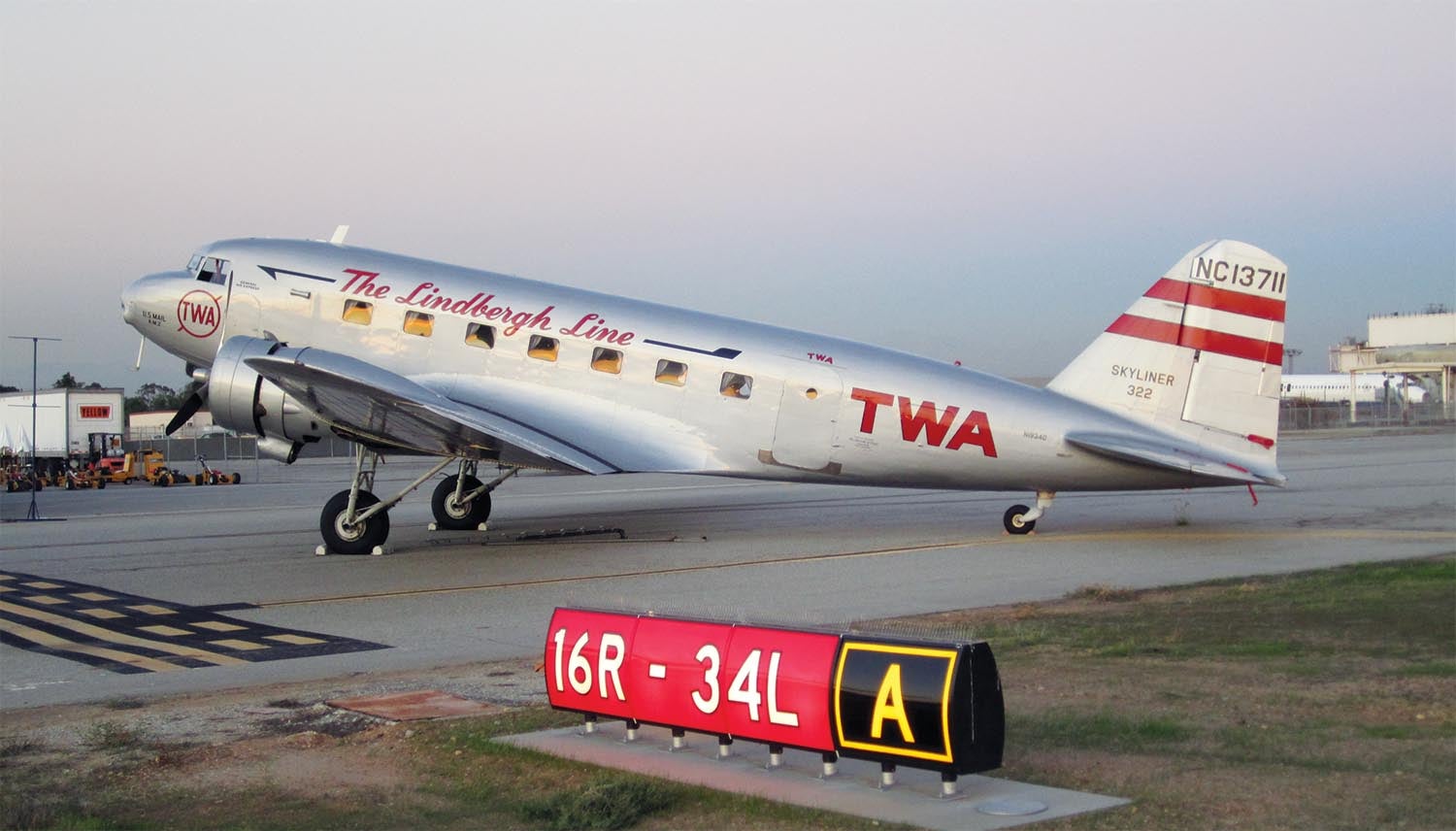
If we look at high-performance piston-engine airplanes, they all incorporate some form of variable geometry that allows the pilot to control the airflow through the cooling system. Variable-geometry cooling systems were incorporated on all piston-engine airliners from the DC-2 onward, as well as WW-II fighters. Some higher-performance general aviation airplanes also have some form of variable geometry in their cooling systems.
The advantage of variable geometry is that it lets the designer size the cooling system to provide optimum cooling flow in cruise or at maximum speed, and use the variable-geometry features to generate the extra airflow needed to cool the engine in climb.
A variable-geometry system provides the best cruise performance. It has some disadvantages too. It is more complex and hence more costly than a fixed-geometry system. It also requires the pilot to monitor engine temperature and manage the settings of the cooling system to control engine temperature.
A final disadvantage of some variable-geometry systems is that they typically have higher drag in climb configuration than a fixed-geometry system. The variable geometry shifts the drag penalty compromise from cruise to climb. On a high-powered, fast airplane there is typically enough excess power that this relatively small penalty in climb is acceptable, but the drag of the cooling system in climb must always be taken into account to ensure adequate climb performance.
Cooling With Minimum Drag
Taking air on board the airplane always causes drag. Cooling drag can be as much as 15% of the total drag of a typical single-engine piston airplane.
Proper design of the complete cooling flow path can improve engine cooling and minimize the drag of the cooling system.
The cooling system should:
- Take as little air onboard as possible.
- Use it efficiently.
- Return the air to the outer airstream flowing backward at the highest possible speed.
Every step along the cooling airflow path—from the inlets, through the engine compartment, and out the outlets—affects both the drag and the cooling performance of the system. Ideally, the cooling air should flow into the airplane, slow down and flow smoothly over the hot parts of the engine and through the oil cooler, and then leave the airplane flowing directly downstream at as close to the free-stream airspeed as possible. It is inevitable that the cooling airflow will lose some energy as it flows through the cooling system, but a well-designed system can minimize this loss.
Next month we will start a trip through the cooling-air flow path with a look at inlets.


Barnaby,
Thank you for this eloquently concise overview of reciprocating engine cooling, culminating in the three “golden nugget” bullet points in the last section–very valuable to us the builders. For lower speed aircraft, I would translate the points to:
– determine the required engine heat transfer at full throttle;
– under “worst case” environmental conditions of air temperature, density, moisture content, etc., determine the required (laminar?) air flow to achieve the previous point;
– optimize expansion of the intake-to-cylinder/oil cooler ducting to achieve the previous point with minimal air intake and the required velocity reduction; and
– optimize contraction of the cylinder/oil cooler-to-outlet ducting to maximize air exit velocity without detriment to the previous points.
Looking forward to the following articles!
Mark Kennedy
Comments are closed.