
Part of going off-plans, or making custom versions of structural items, is that you should be prepared to test these parts at the limit load designated for the airplane. Additionally, you may want to test unmodified parts if they will be stressed beyond the original design’s load limits, say if you plan to change the aircraft category or gross weight.
Since my SR-1 race plane is a clean sheet design, we test a lot of parts. These tests are either a destructive load to determine failure mode and/or validate and guide iterative design of a prototype, or a proof load to verify limit load strength of a finished part. Loading the prototype tailwheel bracket to failure is an example of the former, while a static wing test to 7 G’s without failure is an example of the latter. This three-part series will discuss a variety of tests and how testing can help you design better, safer parts. In Part 1, we’ll look at a static wing test, a test many readers may be familiar with, even if they haven’t done it themselves.
Why Do Testing?
The goal of static wing testing is to apply a load equal to the wing design limit load to ensure that the wing structure is strong enough to handle these loads in actual flight (see sidebar for explanation on load terminology). The load is usually applied in increasing increments of 1 G. This allows the designer to know the actual load at failure if the wing fails before reaching limit load and to modify the design accordingly.
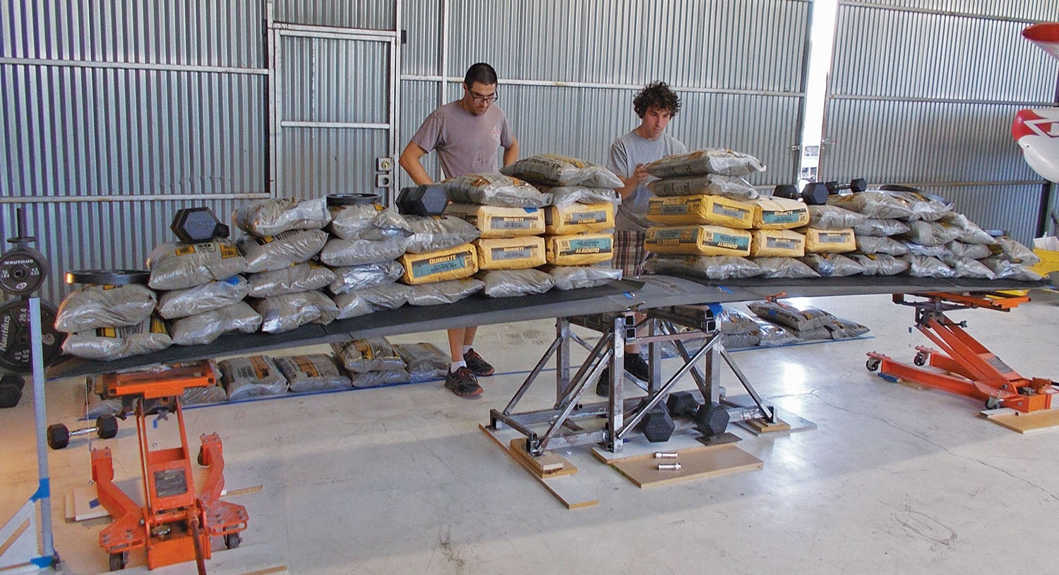
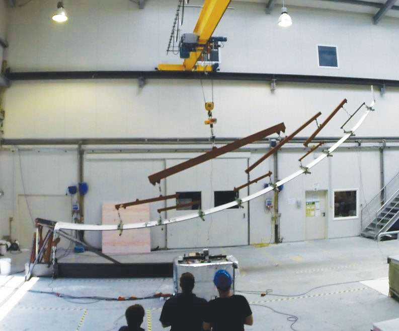
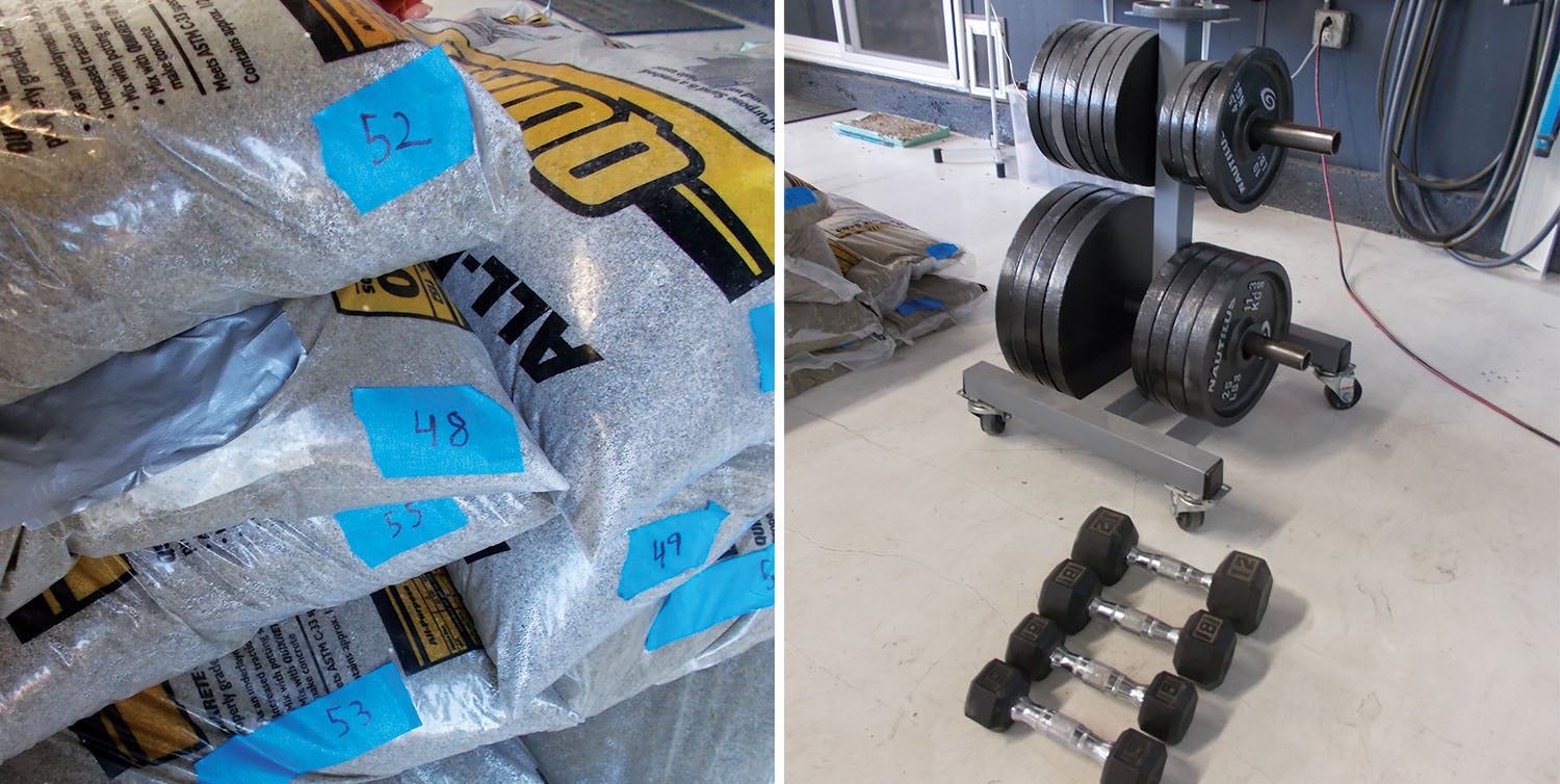
Aerospace companies often use a device called a whiffle tree, which allows the load to be distributed evenly over the entire wing, with force applied through one or more cables at the base of the inverted tree; synchronized hydraulic actuators are also used. For homebuilders, it’s easier to simply use bags of sand or concrete to simulate the load.

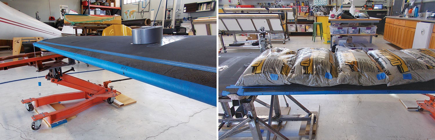
Bags should be applied from the tip moving inwards. This allows the designer to more accurately determine the weak spot if failure should occur. For example, imagine a wing is loaded to the equivalent of 3 G’s. We then begin to apply a load equal to 4 G’s, starting at the tip. At the midpoint of the wing, the spar breaks. It will almost certainly break at, or inboard of, the last bag placed, since placing this bag puts additional load on the inboard section of the wing, but no additional load on the outboard section of the wing. The designer thus knows that outboard of the last placed bag the wing is OK to 4 G’s, but inboard it is stronger than 3 but weaker than 4 G’s. If one moves in the opposite direction (root to tip), there is no information that outboard of the last weight placed the wing is strong enough or not.
Bags should be placed chordwise on the wing so that their center of gravity aligns approximately with the center of lift. If you are concerned about aeroelastic effects, you will need to position the bags aft of this point to simulate torsion caused by the wing’s moment. Since the center of lift is located at approximately 25% of the mean aerodynamic chord, for most homebuilts the sandbags will be set near the leading edge. If the spar is located aft of the center of lift, the wingtips will tend to twist to higher angles of attack relative to the rest of the wing. In contrast, if the center of lift is located aft of the spar, high G loads will cause the wingtips to twist downward relative to the root of the wing.
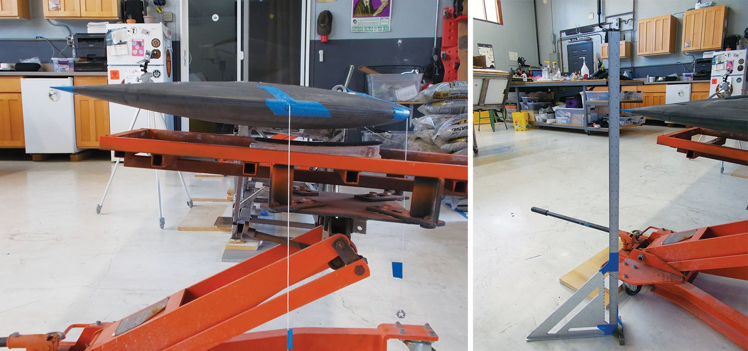
Finally, we must take into account that at the high angles of attack that produce high G loads, the lift vector is actually canted forward. So in addition to a normal force bending the wing up, there is also a component of the force that pulls the wingtips forward. This can be simulated by canting the wing leading edge down during testing; the cant angle is determined according to the calculated lift vector. Thus, it is important to have the drag spar installed on the wing when doing static testing to prevent the wing from folding forward, since most main spars are designed to handle vertical bending loads but not fore/aft loads—that’s the role of the drag spar.
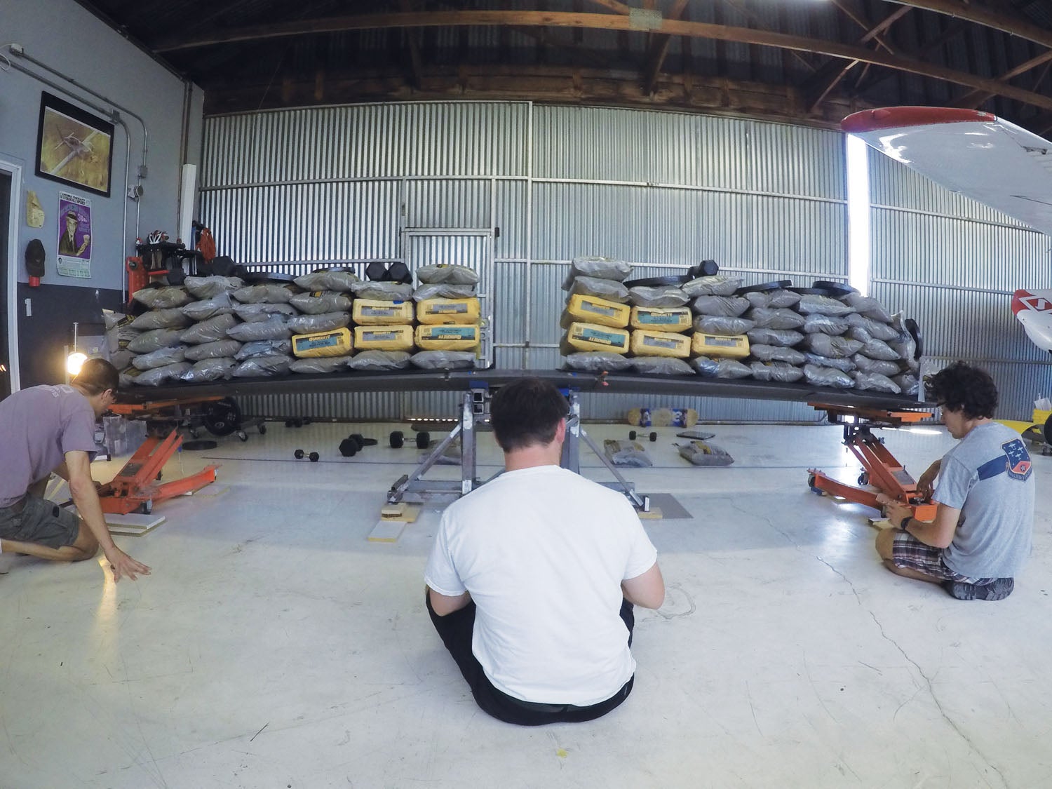
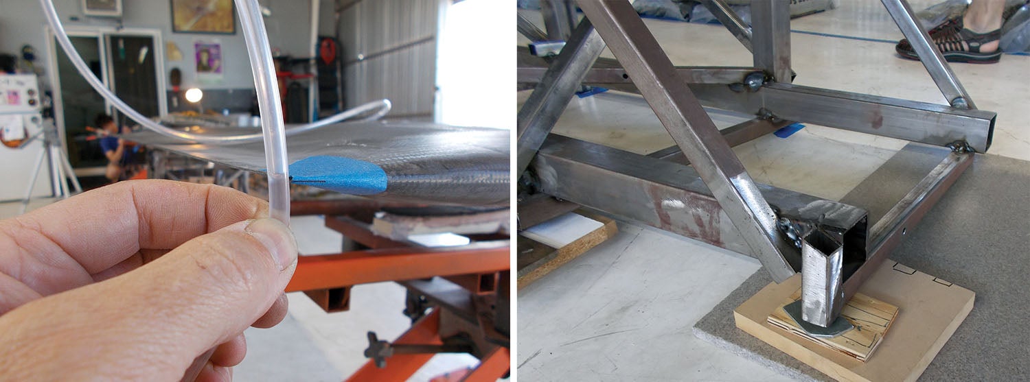
As load is applied, the wing will deflect both downward and, depending on the location of the aeroelastic axis, will rotate tip-up or tip-down. In order to precisely calculate deflection caused by load versus deflection caused by torsion, measurements must be taken at two places chordwise (preferably the leading and trailing edges) as load is applied. However, since the aeroelastic axis is usually pretty close to the main spar for most homebuilts, measuring deflection at the spar will approximate deflection due to load, and measuring the change in chord angle will approximate deflection due to moment.
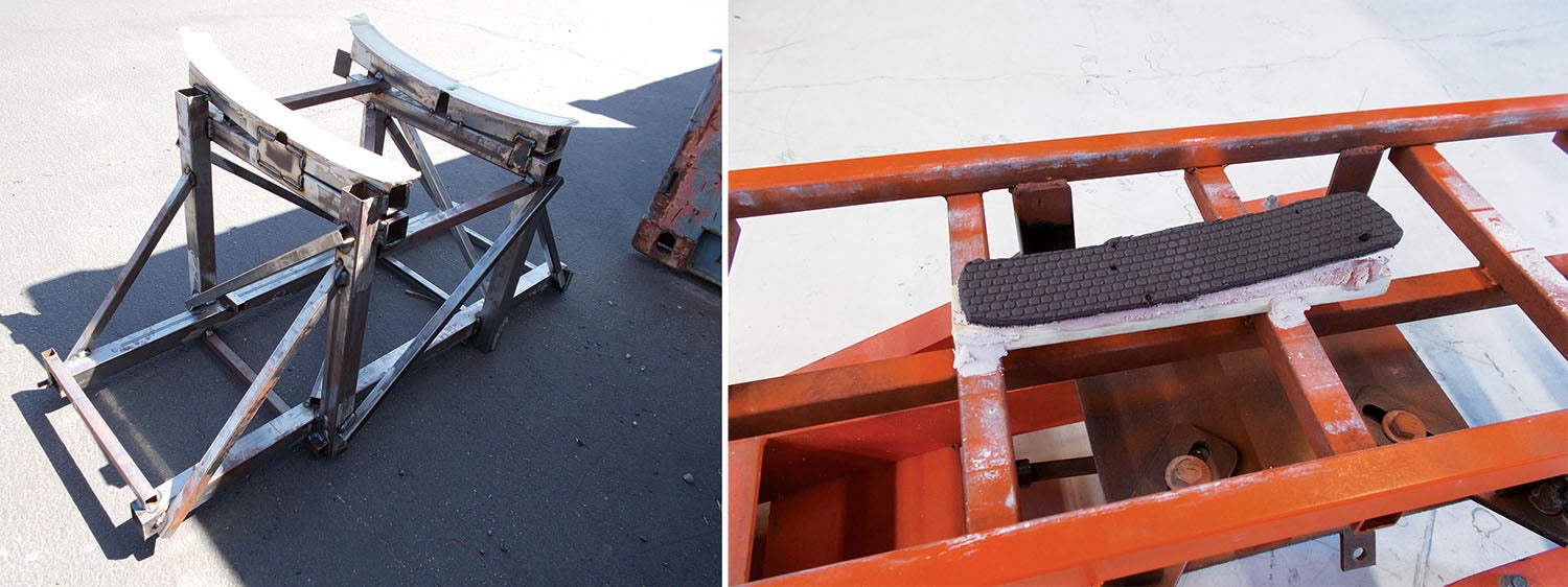
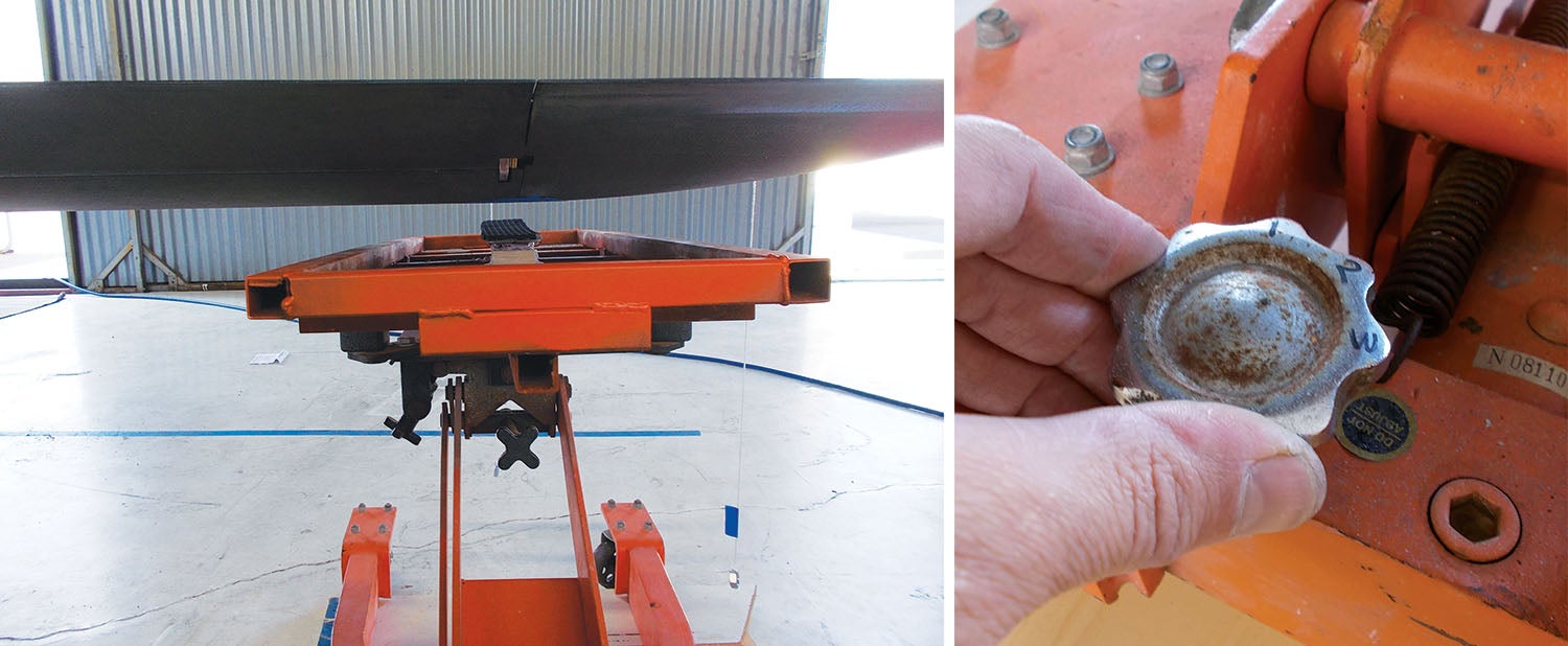
Note that wing load testing can be dangerous due to the large amount of weight sitting on the wing. Asymmetric failure can fling weights in the air or cause structures to move quickly and unexpectedly. For this reason it is advisable to have jack pads or supports under the wing with just enough clearance for the wing to flex under load. That way, if the wing does fail, it only falls a few tenths of an inch until it is arrested by the jack.
Typical Procedure
Typical test procedure is to apply a test load, lower the jacks, inspect the wing as necessary (measure wingtip deflection, check that control surfaces do not bind, etc.), then raise the jacks again just enough to support the wingtips. Although this does not completely relieve the wing of bending stresses, they are significantly lower than when the wingtips are left unsupported. The next round of sandbags is stacked on the wing, and the procedure is repeated until the limit load is reached.
For limit load testing, wings are not required to carry the load for any particular amount of time. For ultimate load testing, the wings must hold ultimate load for 3 seconds before failing. It is therefore advisable to make your measurements and inspections as quickly as possible and then raise the jacks again. When approaching limit load, you will want to exercise extreme caution working near the wing. And while the presence of the jacks may prevent the wing from crashing downward, they do nothing to prevent fore/aft movement of the wing.
Determining loads for the wing is relatively straightforward. The load is simply the G force multiplied by the weight of the aircraft, minus the weight of the wing and any gear or fuel carried along the span of the wing (since these exert an inertial force opposite that of the lift and the two forces effectively cancel each other out).
The spanwise load will be approximately proportional to the chord at that location along the span. For wings where the planform deviates from the elliptical ideal (for example, an RV Hershey bar wing), the lift distribution will approximate something between elliptical and rectangular. Factors such as control surfaces, washout and spanwise change of airfoil section can also affect the lift distribution. Hoerner’s Fluid Dynamic Lift is an excellent reference for calculating spanwise load based on planform.
Tails and control surfaces can also be load tested. This tests not only the structural integrity of the control surface itself but the entire control system since the controls are held fixed during the test. Thus any pushrods, cables, pulleys, linkages, etc. will also be subject to the load imposed on the control surface. Determining the load for these surfaces is not as straightforward as for the wing, but it’s not difficult—the guidelines are provided in the “Simplified Design Load Criteria” in Appendix A to Part 23 of the FARs.

This ends our discussion of wing static testing. There are lots of cool videos on YouTube and elsewhere of wing static tests, from big composite 787 wings on down to traditional aluminum wings. Sonex has some good ones, as does DarkAero, so check them out! In the next two articles we’ll look at some dedicated test equipment and how tests can be used to validate and improve component design.
Photos: Eric Stewart.


Excellent article. Keep them coming!
Very simple and impressive explanation. Congrats.
Comments are closed.