 It usually takes about 8 flying hours to get from Oshkosh to my home airport. The year it took 10 days to get the plane home because of low visibility was the year I decided to get my instrument rating. I was flying a 1974 Piper Warrior at the time, and I upgraded the plane with a Garmin GNS 430 and a King KX 155 to make it IFR capable as well. After six more years, I wanted something faster that I could work on myself. And my wife wanted a high-wing plane as she was finding it harder to climb up on a wing to get in and out. The plane that fit my mission was the GlaStar. I found a well-built one at a good price, but it was strictly VFR.
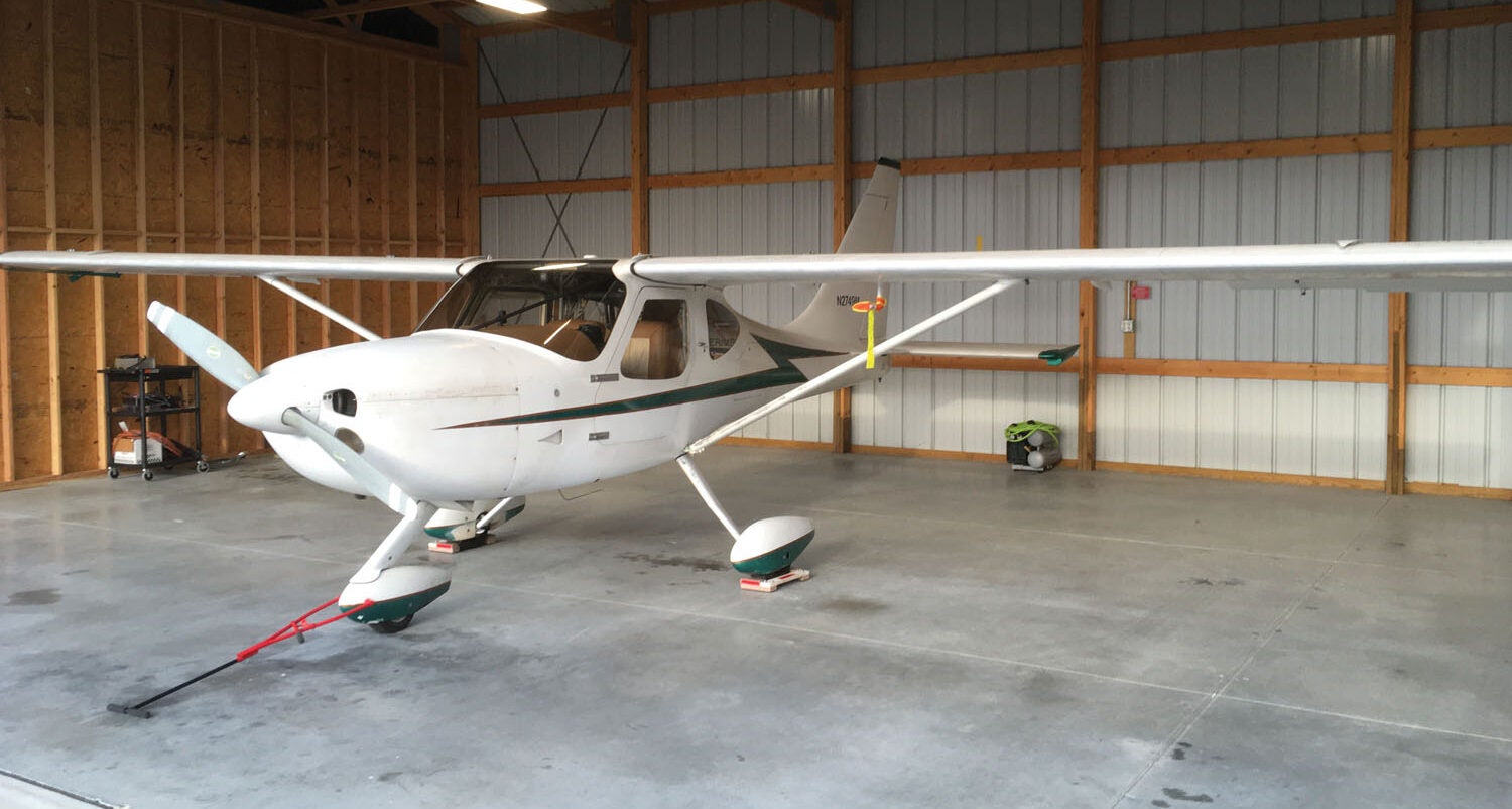
Ever since I bought my GlaStar four years ago, I’ve been thinking about upgrading to glass. The existing panel is clean and simple with a Garmin GNC 300XL GPS/com and a transponder. A Vision Microsystems VM 1000 does the engine monitor work. The spider-looking thing is a mount for my iPad. I wanted to get rid of the vacuum pump and make the plane capable of light IFR. I spent a lot of time debating the options, looking at costs, etc.
Each year at AirVenture, I spent time at all the major vendors playing with their devices. Despite going in with a predilection to buy Dynon, every time I left AirVenture, I felt the most comfortable with the Garmin G3X line. Important lesson—if possible, get some time with the avionics you’re thinking of buying. There are subtle usability differences, and you may find that one box just “falls to hand” while another one makes no sense to you.
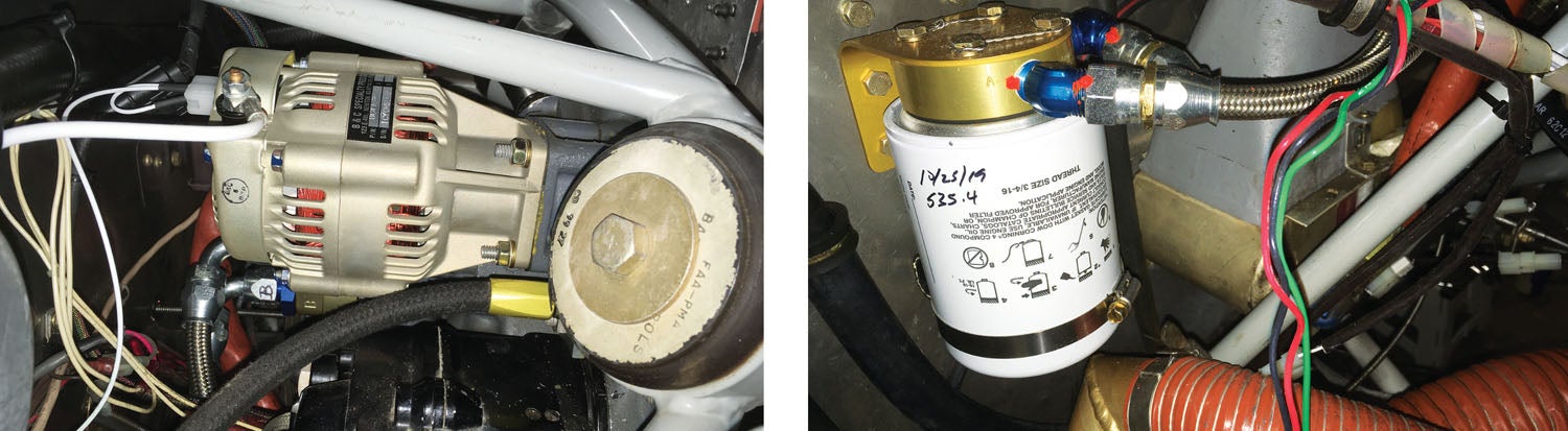
Two years ago, at AirVenture, I bought a B&C backup alternator and a Garmin G5. The G5 was a pretty easy install. I had planned to install the alternator during last year’s condition inspection but was thwarted by the hard-to-reach nut in the bottom inboard corner of the vacuum pump, so I decided to just leave things alone. I took out the vacuum instruments and plugged the pump intake. The G5, front and center, gave me a good taste of flying with a glass panel.
Going Bigger
I strongly considered getting a second G5 and calling it good, but bigger glass kept calling me. One problem is that my panel is relatively short (12 inches tall), and the 10-inch Garmin screen wouldn’t fit without doing a major panel rework. I was hoping to surgically insert the new stuff into the existing panel, but it was too tall unless I relocated the switches along the bottom.
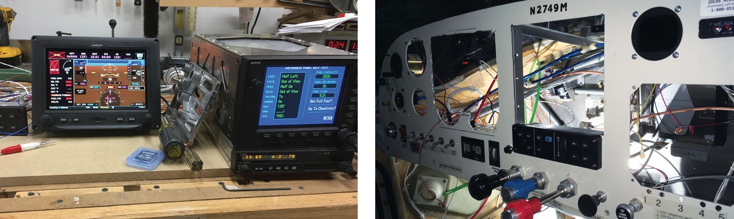
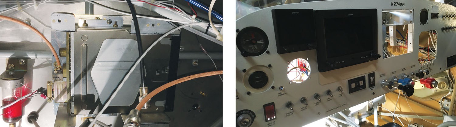
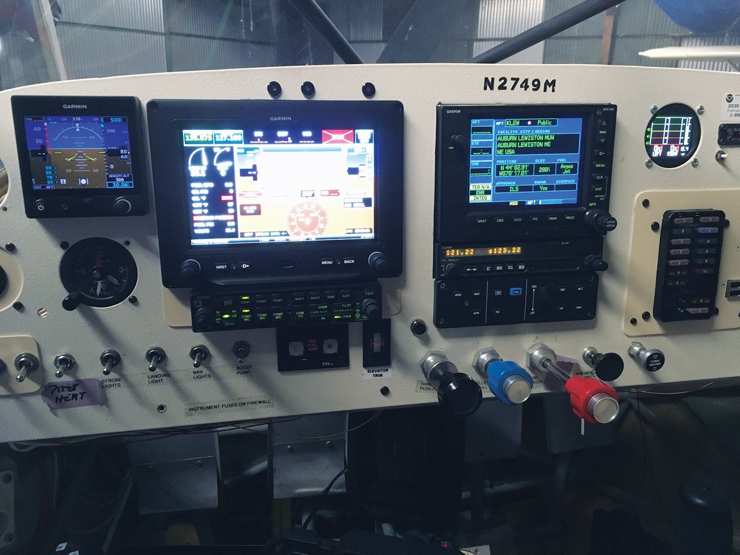
Ultimately I realized that the G3X Touch 7-inch landscape screen almost perfectly fits in the space of four of the round instruments, and a plan was born: Put the G5 where the airspeed is, cut a square hole next to it and we’re done. Yeah, right. But I did buy the 7-inch screen. I also haunted the various places online where people sell stuff—eBay, the Glasair Owners Forum and the Van’s Air Force forum—the latter has a very active classified section. I got good deals on a GMC 305 autopilot head, autopilot servos and a Garmin GPS 500. It’s old but still supported (for now) with a big screen and is fully IFR capable. I also bought an Apollo SL 40 com. I spent a good part of the summer building a wiring harness and configuring everything on my workbench.
For those of you wondering how this kind of process rolls out in more or less real time, here’s an abridged version of my “mod log” for the project. You’ll note that this happened starting in late 2019 and I have, obviously, flown with the completed panel since then. In the second part, I’ll bring you up to speed on my “final” impressions of the job.
November 22, 2019
We had a Young Eagles rally on October 5, so on October 6 I started taking the plane apart for its condition inspection and this upgrade. The inspection went fine, so onto the surgery. Step one is to remove everything that will no longer be needed. A chat with the A&P on the field led me to the magic Rapco wrench that lets you get that bottom nut off the vacuum pump. There was still some cussing, but I got the backup alternator installed.
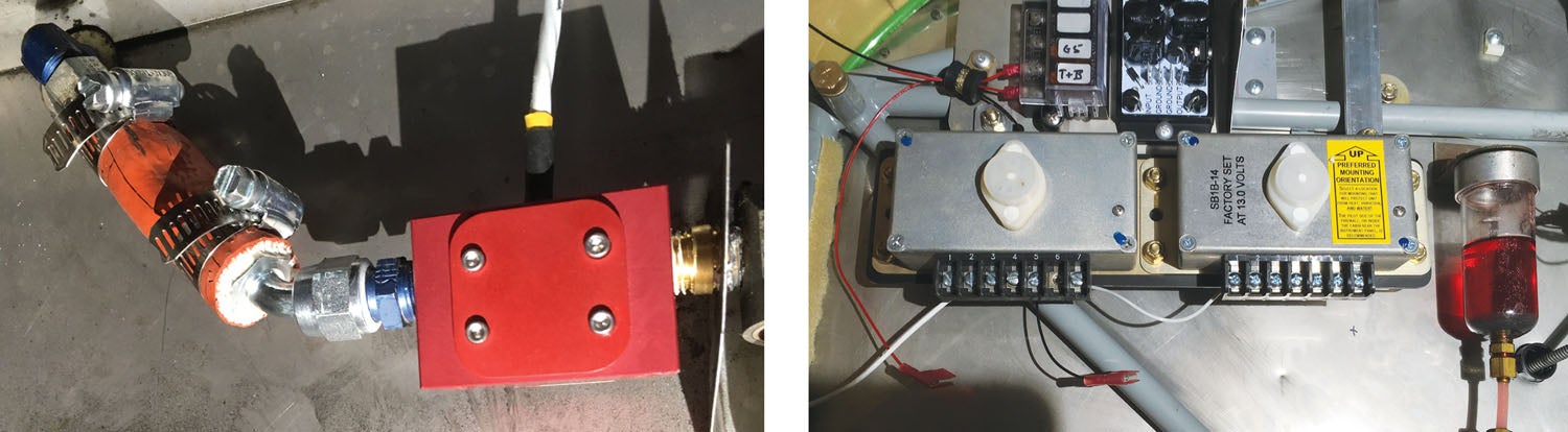
My present to myself at this year’s AirVenture was an Air Wolf remote oil filter. In the stock location, the filter was difficult to get in and out, and I really hated how much of a mess I always made.
Late November
I got all the instruments and avionics out and made my hole. I also cut a hole for the autopilot control head right above the throttle. I built a panel to fit in the space where the VM 1000 display was that has a fuse block and a ground bus in it. All the new equipment will be connected there apart from the autopilot. I prefer a pullable circuit breaker for that. I needed to install new breakers for the new alternator, so I took the time to rearrange all the breakers and to make new bus bars for them.
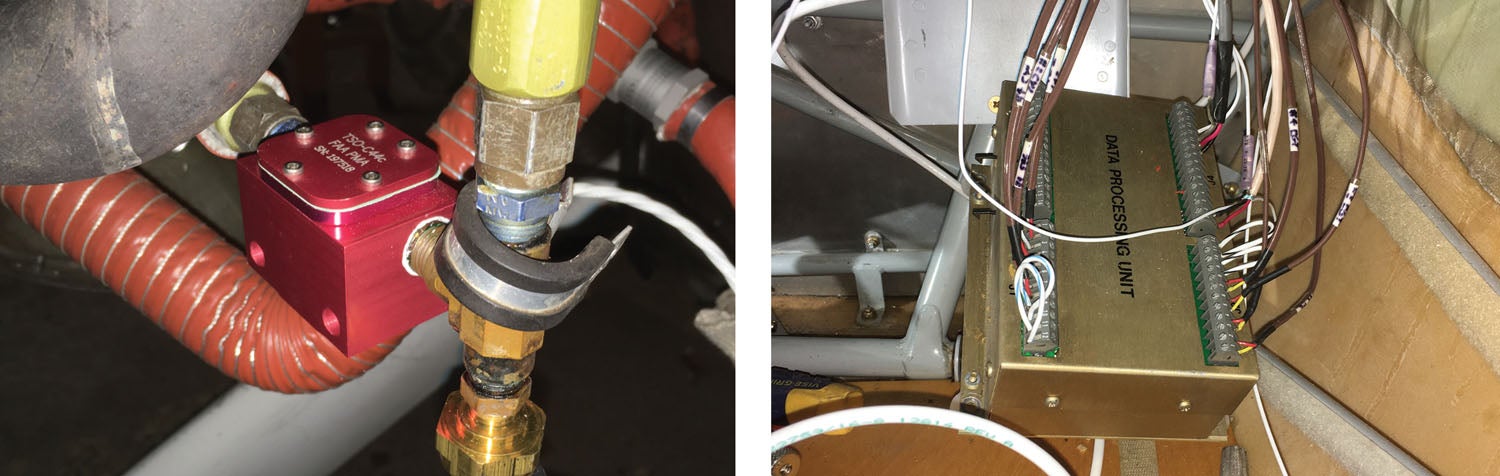
I’ve spent the past couple of sessions replacing the engine sensors. The CHT, EGT and oil temp are compatible with the Garmin G3X suite, but everything else has to get swapped out. This has proven challenging but it is progressing. Tonight, I got the red cube fuel flow installed (although not wired). I hope it proves more reliable than the failed FloScan it replaces.
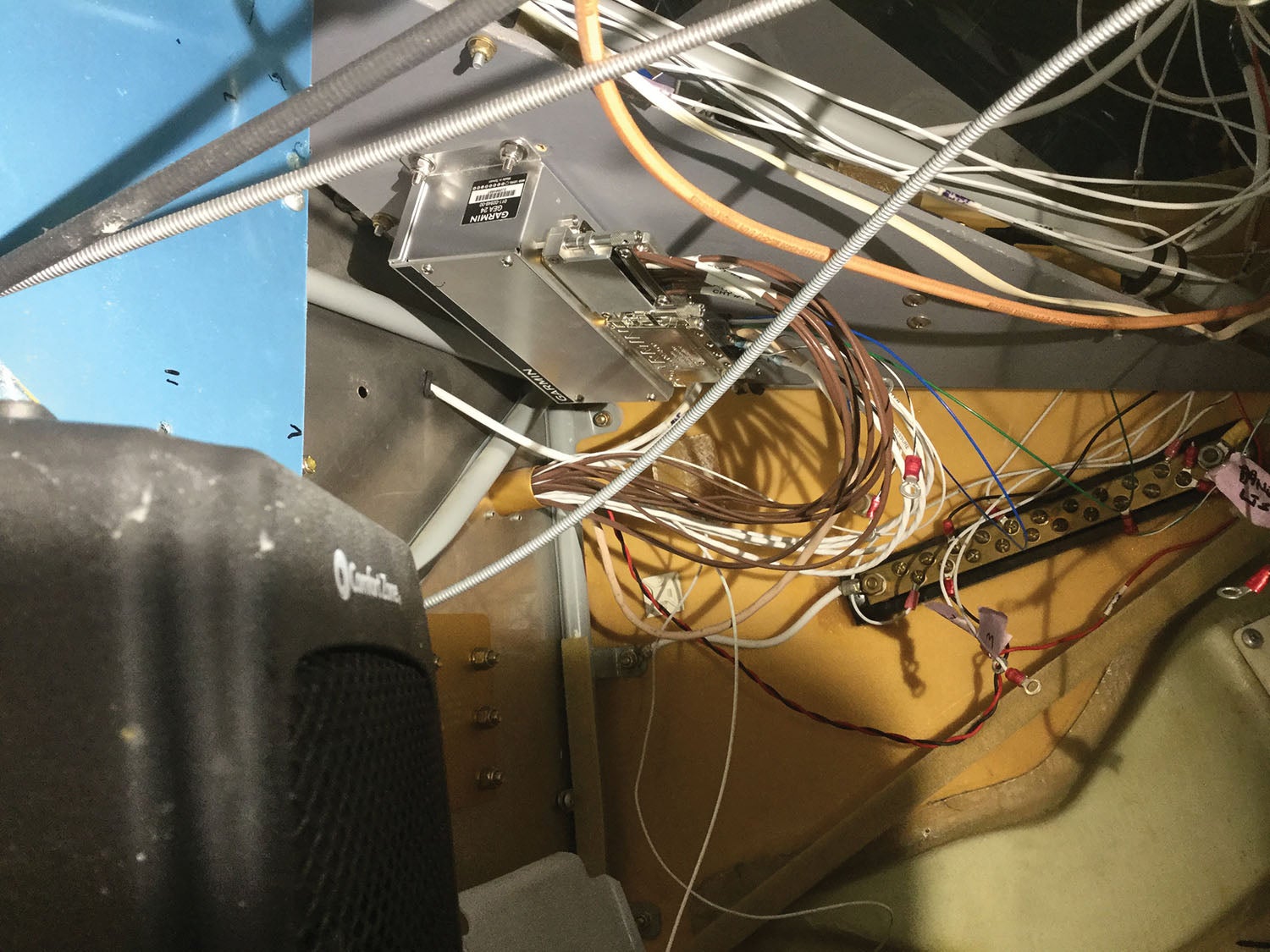
One of the most challenging parts of this has been figuring out where to mount things. I’m still not 100% committed to a spot for the GEA 24—the engine monitor box—and I haven’t figured out where to place the backup voltage regulator at all. Also, my panel is relatively short, and the hole where the avionics go is only tall enough for the GPS 500 and the SL 40. Even though my transponder isn’t technically a remote one, it’s fully controllable via the G3X Touch, so I’m mounting it on the firewall.
Another small rack will hold a GTR 20 remote com when I buy it. And it will also hold the GAD 29 ARINC 429 adapter, which I need for the GPS 500 to talk nicely with the G3X Touch. One nice feature of the G3X is that I can connect to it via Bluetooth and copy flight plans from ForeFlight or the Garmin Pilot app to the GPS 500.
In anticipation of that second com, I also bought an audio panel. I haven’t decided where that’s going to go. There is space right below the G3X screen, so maybe there.
It’s especially fun doing this work in an unheated hangar when it’s below freezing. Fortunately, most of the time, it’s been in the 40s, so I don’t freeze up too bad.
December 7, 2019
I had hoped to have four solid days over the Thanksgiving break to work on the plane, but alas, fate intervened. In fact, today was the first day I’ve been able to work on it in almost two weeks. I got the last of the engine sensors replaced. I am re-using the CHT and EGT probes and the oil temp as they’re compatible. I pulled the EGTs earlier, and they look like they still have life in them. I’ve installed new manifold pressure, oil pressure, fuel pressure and fuel flow. The previous fuel flow was immediately off the engine fuel pump and considerably above the carburetor. The instructions for the red cube want it mounted much lower. After trying several options, I opted to mount it right where the fuel enters the engine bay. One advantage of that location is it also measures fuel pumped by the boost pump. The previous installation did not.
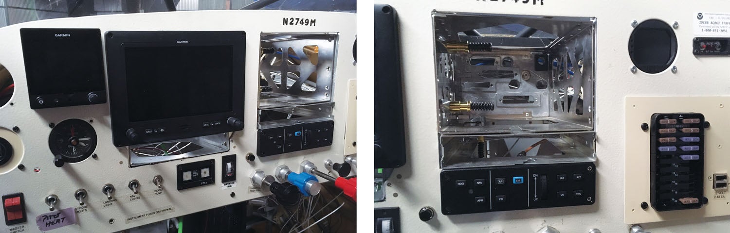
I did decide to mount the audio panel right below the G3X, and my other task today was cutting that hole and riveting in a couple of mounting brackets. I also riveted in the bracket that holds the G3X. While not technically necessary, this will allow me to remove the unit without having to take the glareshield off. Finally, I relocated the clock to the space below the G5. With my iPad in the corner, it completely hid the clock in its previous position.
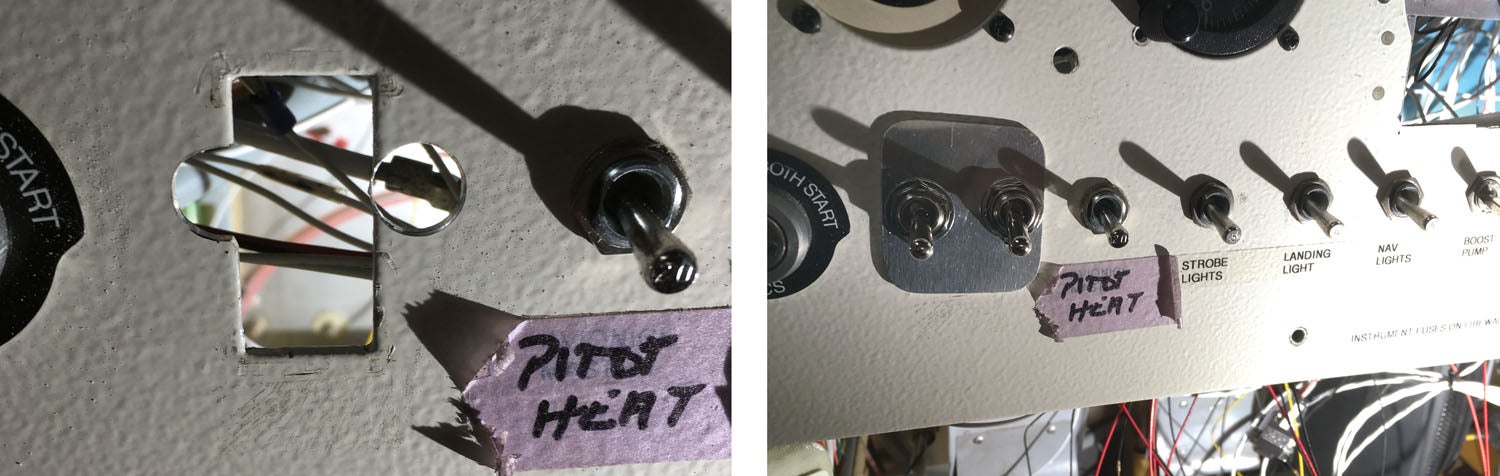
A panel on the right side of the instrument panel covers up the hole where the VM 1000 was. Yes, I am using fuses for all the new instruments. I built that panel to mount behind the hole, and I may still. But if I mount it in front, it covers up the five push-button holes along the bottom edge. They are probably a good conversation starter anyway. If I decide to leave it this way, I’ll make the edges and corners a bit prettier.
December 16, 2019
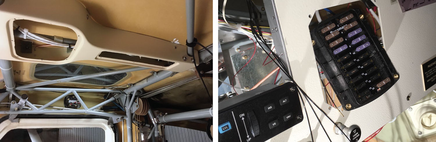
As I said before, figuring where and how to mount stuff has been a real challenge. I think today I finally finished with all of that. The old voltage regulator was blocking access to the spot I wanted for the GEA 24 engine monitor box, and I also needed to mount the new voltage regulator. I decided to relocate them both to the pilot’s side of the plane.
The electro-gizmos above them (see the photo lower right) is a capacitor-based voltage stabilizer. The previously installed electronic turn-and-bank instrument would lock up during engine start because it was, apparently, quite voltage-sensitive. This unit stores a charge in the capacitors and uses it to maintain 13.4 volts through any brown-out event. When I shut the plane down, it would keep the T&B running for about 2 minutes. I plan to use it for the backup power feed for the EFIS, although I’m sure it won’t last 2 minutes.
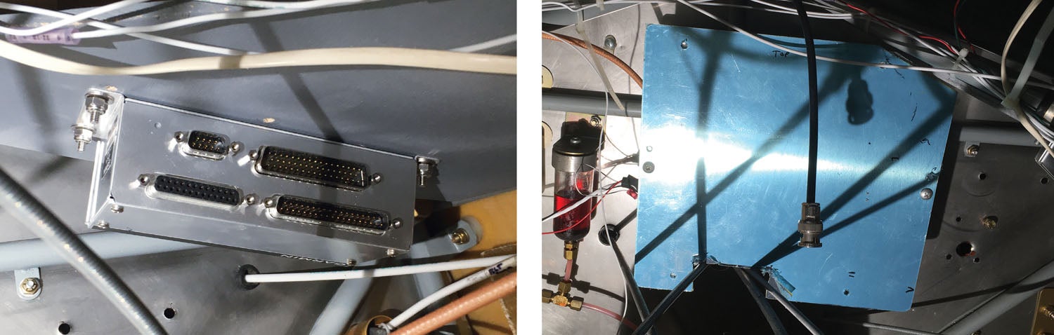
Because I have experienced a com failure, I required a second com radio for IFR—and because there is no room in the panel, I opted for a Garmin GTR 20 remote com. The G3X controls it. It is mounted to the other side of that blue panel that covers the transponder.
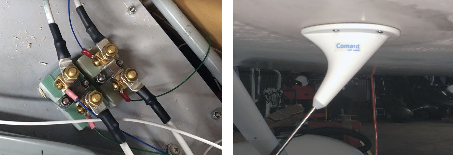
I struggled mightily before buying that radio with where to locate a second antenna. Based on comments on the Glasair Owners Forum, I decided to buy a Comant bent-rod antenna, and I’m going to mount it on the belly. I just couldn’t find an internal mount that met distance requirements from all the other antennas I have. Also, I’m stealing another good idea from there. I mounted the OAT probe under the wing just behind the pilot door.
As I’ve been going through this process, I’ve been examining all the existing wiring, taking out what I won’t need and, in some cases, redoing what was there. I think I’m at the point where I can start installing the new wiring harness and attempting to make it all neat and pretty.
I am, for now, forgoing installing the autopilot servos. I want to get the front-end all buttoned up, calibrated and validated before it gets too much colder. I’ll tackle the servos as a separate project later. I have run the wires, so that project will take place entirely under the seats.
December 21, 2019
The “brain” on the VM 1000 used screw terminals. I was very careful to leave the wires attached until I had identified correctly what each wire did. I still had to make some educated guesses as the VM 1000 manual referred to red and black, and the Garmin documentation calls out HI and LO. I kept the wires and sensors for EGT, CHT and oil temperature. Everything else is new. I also replaced the labels on the existing wires. The builder had written labels in pen and covered them with clear heat shrink. Over the years, the ink bloomed, making them illegible. Garmin uses D-sub connectors, so I’ve spent some quality time leaning in through the door, trimming wires and crimping pins on them and then carefully making sure they go in the right spot in the connector.
(Pro tip for those in colder climes: I used a space heater in the cockpit to keep my hands thawed. It was 26° F when I got to the hangar this morning.) It’s supposed to warm up a bit this coming week, so I’m hoping I can make some major progress before the end of the year.
December 22, 2019
Today was warmer—50° F—which was nice, and I spent about 6 hours working on this. At the end, though, it was one of those times when I felt like I hadn’t accomplished a lot and there was so much left. Anyway, the first task was to replace the split-rocker master switch with a three-position progressive toggle switch and a second switch for the backup alternator. The three-position switch allows me to run the main battery alone or the battery and the main alternator.
I took a stab at getting the field wires from the alternators over to the voltage regulators but wasn’t happy with the routing, so I decided to look at something else for a while.
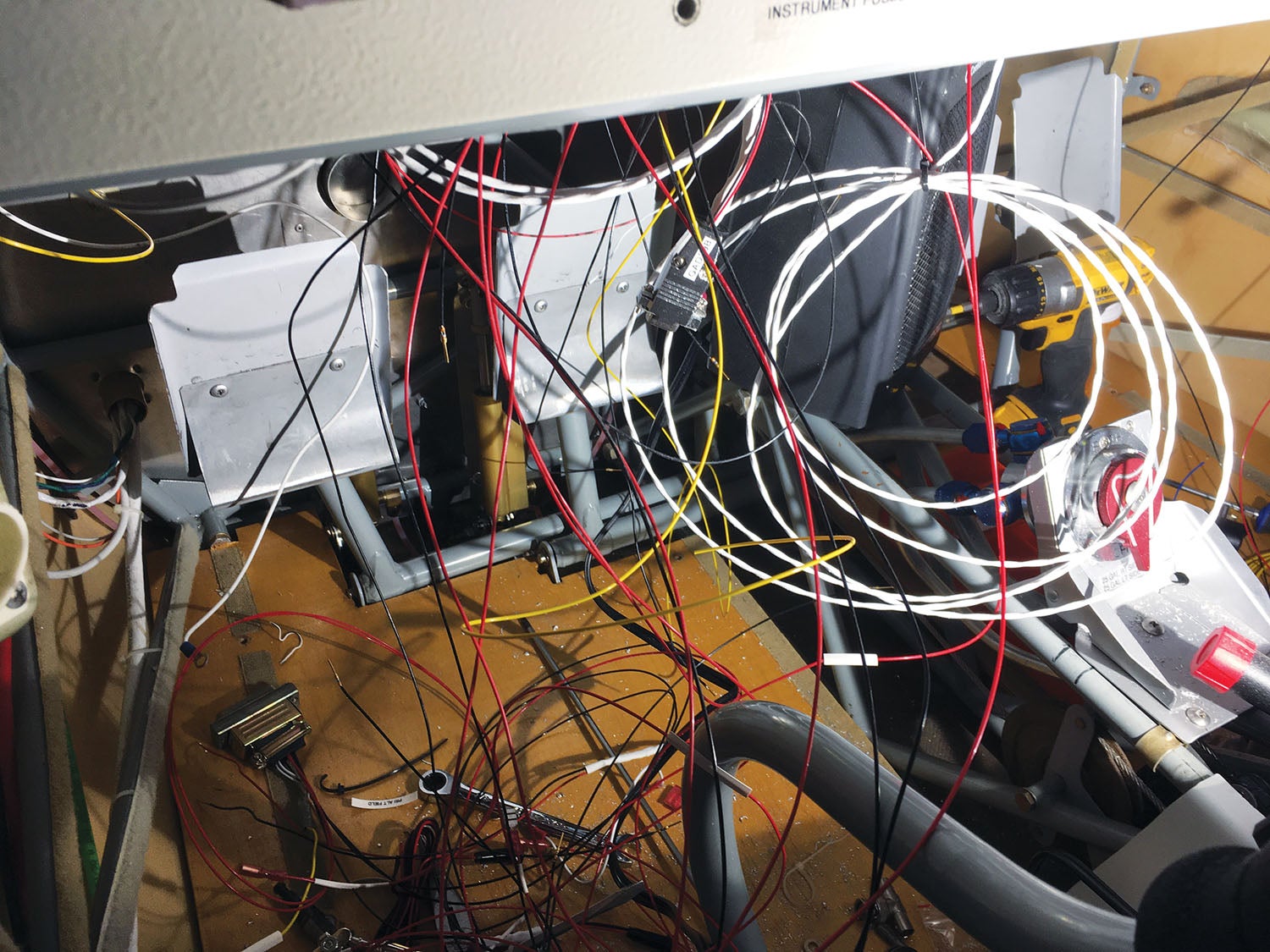
That “something” was to drop my prebuilt wiring harness into place to see if everything would still reach, as a few locations changed. It’s kind of like wrestling a bag of snakes, but it mostly settled into place.
December 30, 2019
I spent most of the weekend at the hangar. It was “comfortably” in the upper 40s. Wearing layers and the little space heater in the plane makes it reasonably comfortable. Saturday’s major accomplishment was installing a second current shunt.
The sensor kit came with one, and I installed it on the B-lead from the primary alternator. The shunt can be installed on the battery lead, in which case it shows charge and discharge rates, or on the alternator where it shows the load on the alternator and, therefore, the current all the equipment is using. I prefer the latter because I feel it gives me a better picture of what’s going on. The Garmin G3X can support two shunts. I’m sure many people put the second one on the battery lead, but since I have two alternators it makes a lot more sense to monitor the second one.
The rest of the day was cleaning up some of the existing wiring and sorting out the grounds on the two voltage regulators. I still have to run power and install the low-voltage warning lights. Sorting out where to mount my warning lights is turning into a chore. Because of the small panel size, there is not a lot of free space within the proper field of view. I potentially have five lights: warn and caution from the G3X, caution from the LASAR ignition system and low-voltage from both the primary and secondary alternators. I’m also debating whether any of these will get turned into inputs into the G3X instead of lights.
I was awake half the night Saturday trying to figure out how I was going to run the cable from the new com to the new antenna. Because I don’t have the tools to crimp a BNC connector, I ordered a prebuilt cable. What occurred to me was that the normal openings I run wires through are not big enough for a BNC connector. So when I got to the hangar on Sunday morning, solving that mystery was job one. I won’t keep you in suspense: I ran it down the front copilot corner of the firewall, below the fresh air intake, and by prying with a hammer I was able to make a large enough gap between the fiberglass fuselage shell and the lower diagonal tube to squeeze the BNC through.
January 1, 2020
I had gone through some of the OAT probe placement discussions on the Glasair/GlaStar owners forum and decided the solution I liked best was just behind the pilot’s door. Easy access on both sides yet out of the way of my head, engine heat and sunshine.
The other task, which I didn’t quite finish, is the headset/mic wiring. The plane came with a Sigtronics intercom mounted above, behind and between the seats. I liked the location for the jacks because it does keep the cords out of the way, but because I’m adding a second com I’m also adding an audio panel that has an intercom built in. Because I’m switching from mono to stereo, the wiring isn’t the same. I installed all new jacks in the overhead console connected to a DB-25 connector. That’s to allow easy removal if I need it. That part I had done during my basement mockup. Today I ran the wires from the audio panel, terminating them on the mating DB-25. I started terminating them on the audio panel, but it was the end of the day, and I put the wrong size pins on the first two, so I decided it was time to stop. This is just one small indication of how changing one component can have wide-ranging implications.
January 9, 2020
I skipped out of work this afternoon and made some progress. It was 40 and sunny. I left the hangar door open for the light. The wind kicked up but wasn’t blowing in so I didn’t pay much attention. Then it got dark, and a snow squall came out of nowhere. It was coming down. I did shut the door then because it was blowing in on me. About 10 minutes later, the sun came out again. Oddly enough, the only plane I heard take off this afternoon was a Cirrus that took off during the blizzard.
I installed the three idiot lights that I’m not virtualizing in the G3X. They are the three black dots above the EFIS cutout. Left is master warning, next is master caution and the one on the right says the standby alternator is in use. Primary alternator low voltage and LASAR status lights are going to get connected to the engine monitor box to be displayed on the screen. I have extended those wires to the box but haven’t started putting the connector together yet. At this point, though, I can declare both voltage regulators fully wired.
I also slid the radio racks into place and attached the connectors. It’s certainly easier working back there without them in place, but I need them there to make some wire routing decisions.
I still have to tap into the left and right fuel gauge wires. I’m keeping the Belite Radiant fuel gauge I installed a couple of years ago because I really like it, so I need to tee off wires to the Garmin. It’s supposed to be near 60 this weekend, so I’m planning on spending time both days working on this.
January 11, 2020
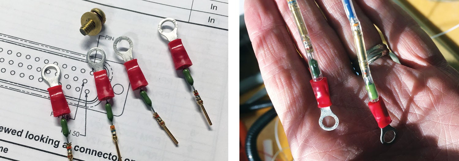
The weather forecast was pessimistic. It was sunny and 64° here today, and I spent about 6 hours working in the hangar. The order of the day was to finish getting the GEA 24 engine monitor wired up, and the first thing I did was add fuses to the shunt sensor wires. (The shunt is “live” whenever the airplane is running and should be protected against shorts in the wiring or the sensing systems. Lest bad things happen.)
I picked up some 1-amp pico fuses. I like these because they are small, light and cheap. The easiest way to add them in-line was simply to use a D-sub pin and socket. That also makes them replaceable without shortening the shunt wire, although odds are they’ll last the life of the plane. I started by making up the little fuse assembly.
Oddly, the largest connector on the GEA 24, which has 50 pins, also has the fewest wires connected to it. That’s because it’s dedicated to ancillary functions. All I needed were the two fuel tank sensors, input from the TOGA (take off/go around) switch, input from the LASAR and primary voltage regulator, a line to the bus to measure voltage and the outputs to the master warn and master caution lights.
I spent a lot of time sorting out the wires on the pilot’s side. It’s odd how you can be very careful laying out the wires while making up the connectors on the bench, and yet somehow when they’re behind the panel, you’ll find a wire from one connector crossing through the middle of an unrelated bundle. So far, I’ve been able to get things reasonable without having to pull a wire out of a connector, but it wouldn’t surprise me if it comes to that before I’m done.
January 12, 2020
I had a very productive day. I can see the light at the end of the tunnel. Hopefully, it’s not an oncoming train! My brother helped me get all the holes in the firewall patched up. Remember, also, that I intended the new fuse panel to fit behind the hole where the VM 1000 was. Looking at the logistics of future service, I decided that mounting it in front of the hole was the better idea. So, while I worked on tidying wires and feeding power and ground wires, I had brother Jeff go at it with a file to round off the corners and edges. I brought it home tonight for some finishing touches and a repaint, but I did remove the fuse block and got almost all the power wires connected to it.
Of course, I was noting what I connected to each fuse as I went, and when I was out of red wires, I realized one was missing. Somehow when I wired up the GTR 20 remote com, I neglected to install power or ground!
January 15, 2020
Four hours of work and reached a major milestone. The first thing was to correct the missing wires to the GTR 20. That was fairly straightforward. The hardest part was feeding the wires through the zip ties I tightened up during the last session. Lesson learned there. I did have to cut and replace two but got them through the rest easily enough. Finally, it was collating, bundling and trimming to length all the grounds. I installed the plate with the fuse panel. The ground block is mounted on the back of it.
As Bob Nuckolls suggested in The AeroElectric Connection, my ground block is a mated DB-25 connector pair. The female half has all the sockets soldered together and connected to a pair of 14-gauge wires (for redundancy). To install a ground wire, you just crimp on a male pin and push it into the back of the connector. Easy, reliable and takes very little space. It turns out to be a little tricky finding the holes when it’s behind the panel, and most of the nice big access holes have been closed up. I finally figured out that if I climbed in and knelt on the crossbar that runs in front of the seat, I could get my head over the panel to see what I was doing. The first three wires took me about 20 minutes. The remaining 17, about 10.
Then I closed my last remaining access hole by installing the GPS 500 and SL 40. Coincidentally, one of my friends—a Bearhawk builder—walked in the hangar just in time for the big moment of turning on the switch.
The lights all came on and all the smoke stayed inside the boxes. I ran through the configuration and added the GTR 20 (remember, I didn’t have it when I put this together on the bench) and almost everything looks good.
Two Problems for Another Day
One problem is the oil temperature. That’s the one sensor I didn’t swap out because the one that was in there looked, externally, identical to the new one, and the old one has a tiny hole for safety wire. But it’s not registering, so either it’s not compatible, or I have a wiring problem. More debugging later.
The second problem is the transponder. It’s a GTX 327, and when I had everything together on the bench, I proved that I could control it from the G3X. This was important because even though it’s not really a remote transponder, I didn’t have panel space for it. It worked. I put it back in the plane, but to use it as a standalone transponder, I had to reconfigure it to disable the remote control stuff. Well, I forgot to re-enable it before I got it all tucked up against the firewall. I made a stab at it today—I can reach the buttons and almost read the screen but not at the same time. I am going to have to crawl in on my back, I think. Or pull it out.
That’s enough for now. At this stage of the project, I’m finding that preparation and patience are nearly as important as money and skill. More about that and the many open items still to manage in the next installment.
![[Credit: JetStream Rider]](https://www.kitplanes.com/wp-content/uploads/2026/04/AdobeStock_345999332.jpg?w=218&h=150&crop=1 "2026 Avionics and Lights Buyer’s Guide")
![[Credit: Radiant Technology]](https://www.kitplanes.com/wp-content/uploads/2026/04/550095_5165745cc27748a598699799d796fd94mv2.jpg?w=218&h=150&crop=1 "Radiant Technology Unveils SafeGyro")
![[Credit: Dynon]](https://www.kitplanes.com/wp-content/uploads/2026/04/EMS-stand-alone_HDX.png?w=218&h=150&crop=1 "Dynon Unveils Scalable Engine Monitoring for Kitbuilders")


My Grandfather built this plane! Tons of memories from my childhood sitting right seat and even logged a few hours in it when I was finishing up my flight training. Love the upgrades you’ve done and its so nice knowing its in good hands!
He did a fantastic job. I haven’t found a single thing that I would consider “builder error.”
Rick, I sent this article to my Dad and he was SO elated that the GlaStar he built was still going strong, and in “new and improved” condition. He got his logs out and wanted to know how long ago he first flew the bird he called “Green Hornet” (he still swears that once he added the green bolt on the fuselage he got 5 more knots of performance! Ha ha
As my son mentioned, all of my kids took many rides with me, one focused on flight training, the others along for the best view ever. Paint and panel is what the Hornet needed, and you’ve surely got that wrapped up. Thank you for sharing Sir..Enjoy!
Here’s a note from Dad (Bob Boyd):
GLAD TO SEE THAT THE GLASTAR THAT I BUILT AND FIRST FLEW ON 27 SEPTEMBER 2001 IS STILL FLYING!
LCDR ROBERT L. BOYD, USN RET’D, NOW 91 YEARS OLD.
Comments are closed.