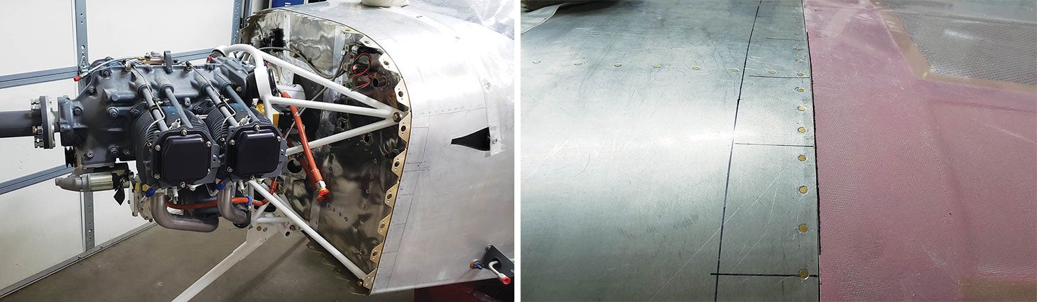
In Part 1, we built David Howe’s EZ-COWL jig and installed it on the crankshaft. The jig helps determine the correct location for the front of the cowl. It ensures we will have a uniform spinner-to-cowl gap and that the cowl will be aligned to the center of the crankshaft. With the jig in place, it’s time to put the two halves of the cowl together and begin fitting them to the forward fuselage.
Step 1
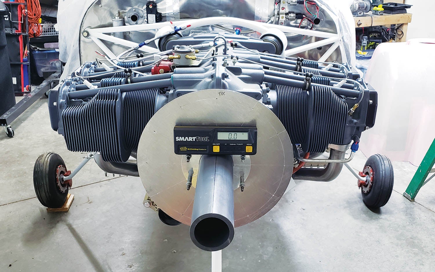
Level the airframe both ways. The cowl split line should be aligned to the airframe. Otherwise, those judges may notice the cowl split isn’t perfectly aligned to the longerons. Keeping the airframe level just makes it easier to use a level for final adjustments. Lateral level (roll) is easy. A shim under a tire is adequate. The longitudinal level (pitch) helps trim the sides so the split is perfectly in line with the longerons.
Step 2
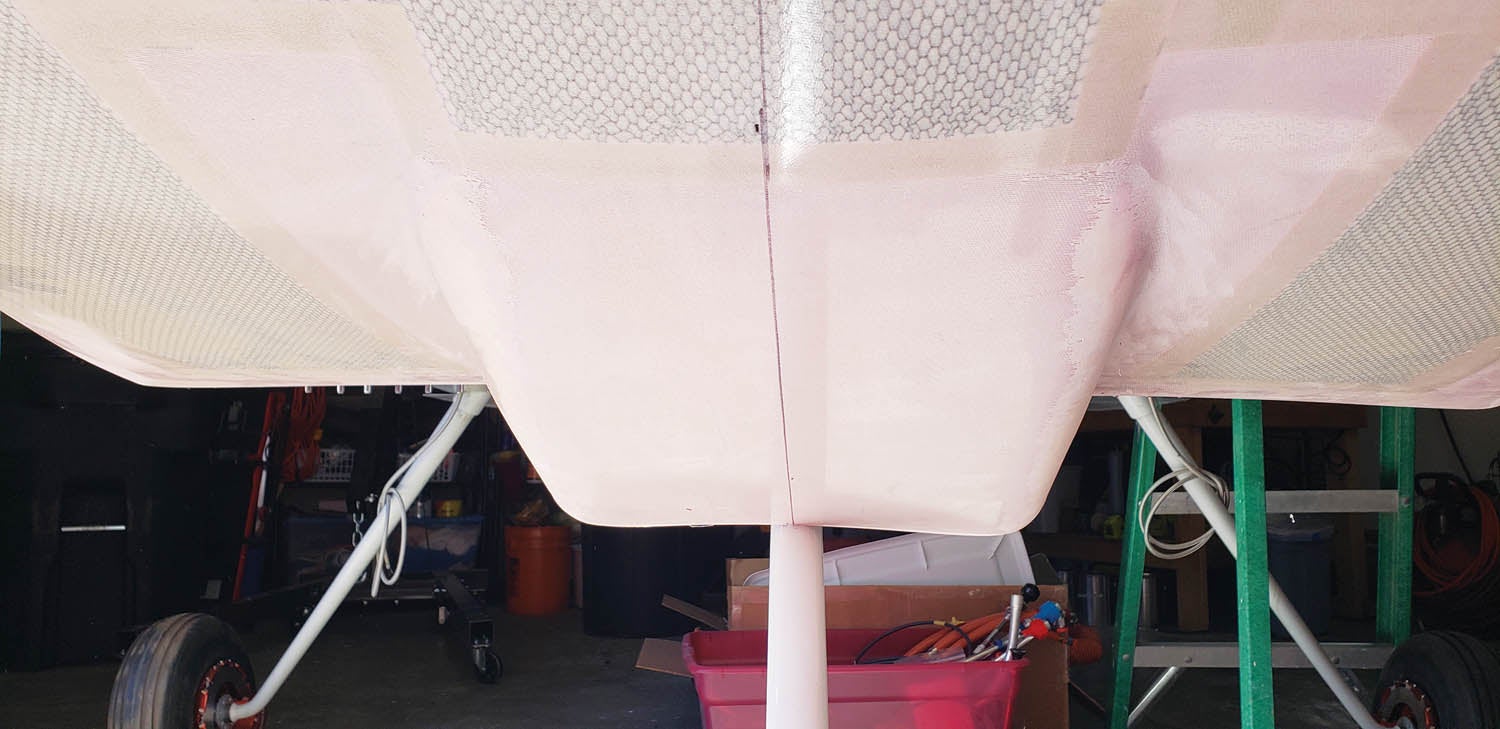
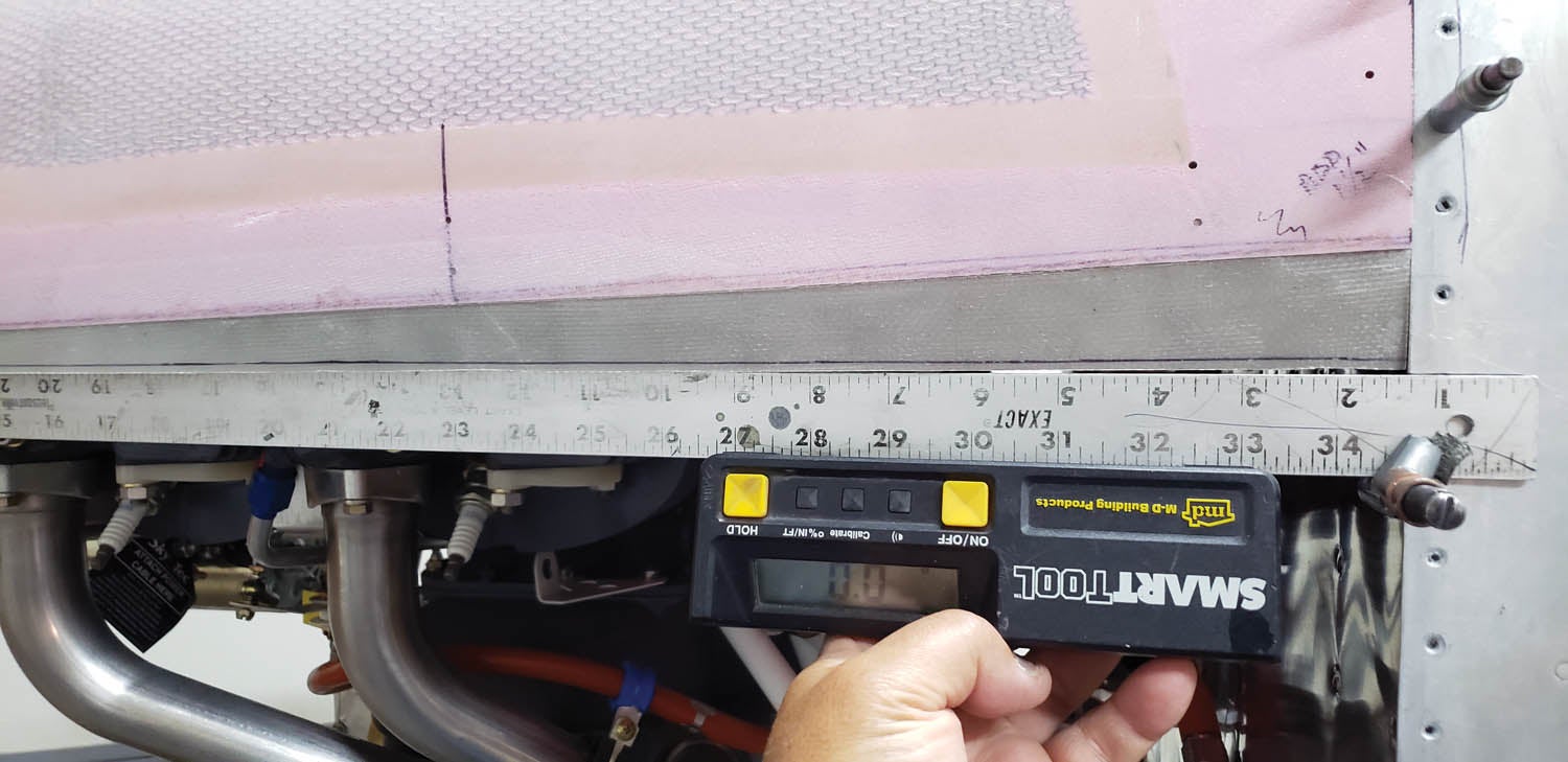
Find the center of the top and bottom fuselage skins and draw centerlines from the firewall aft about a foot. Next, make tick marks on the forward fuselage skins exactly 2 inches from the firewall flange edge. Connect the dots to make a line all the way around—top, sides and bottom. It’s a reference line and you’ll need it later.
Step 3
This is important! Do not trim the side seams or the firewall edge of the cowl yet!
Set the cowl down on the floor, nose bowl up, with the nose bowl parts together. Get a six-pack of beer. Stare at the cowl. Drink. Stare. Drink. Eventually, the brain will click or you’ll pass out. Kidding, of course. Every cowl is different, so I can’t help make it perfect, but I can offer some sequencing advice.
Step 4
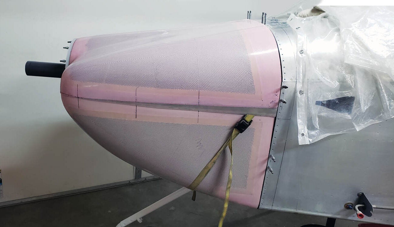
Grab a Sharpie. We need a centerline fore and aft, from nose bowl to firewall, on both the top and bottom cowls. Unfortunately, the cowls are basically round and finding center is tricky. I found my wife’s sewing tape very useful for measuring the curved surfaces. Measure from a side edge to the opposite side edge. Make a tick mark at the halfway point. Repeat several times. Connect the tick marks. The resulting line should intersect most of the tick marks and will be adequate for our needs. It’s kind of like herding cats.
Step 5
Place the cowl on the floor, nose bowl up. Assemble the top and bottom cowl halves so the cowl nose bowl fits together. The sides of the cowls will probably overlap. That’s OK. The upper and lower halves of the nose bowl should form a horizontal horizon line at the nose bowl. It may intersect the lateral center of the crankshaft, or it may be a little above or below. If above or below the crankshaft centerline, it won’t matter. It’s more important that the nose bowl matches the spinner. The horizon line won’t be noticeable. I’m not quite that OCD so I left mine alone.
Step 6
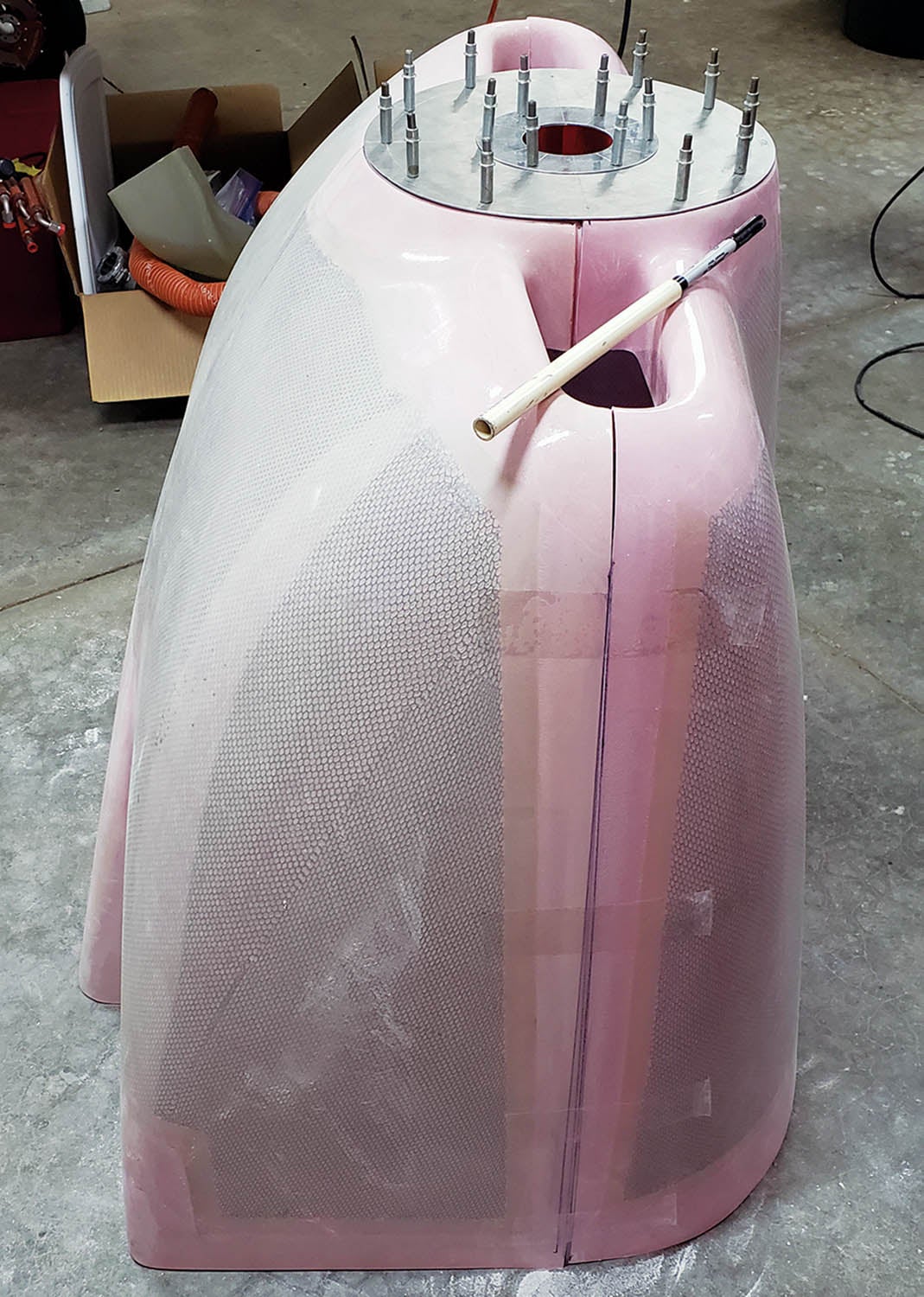
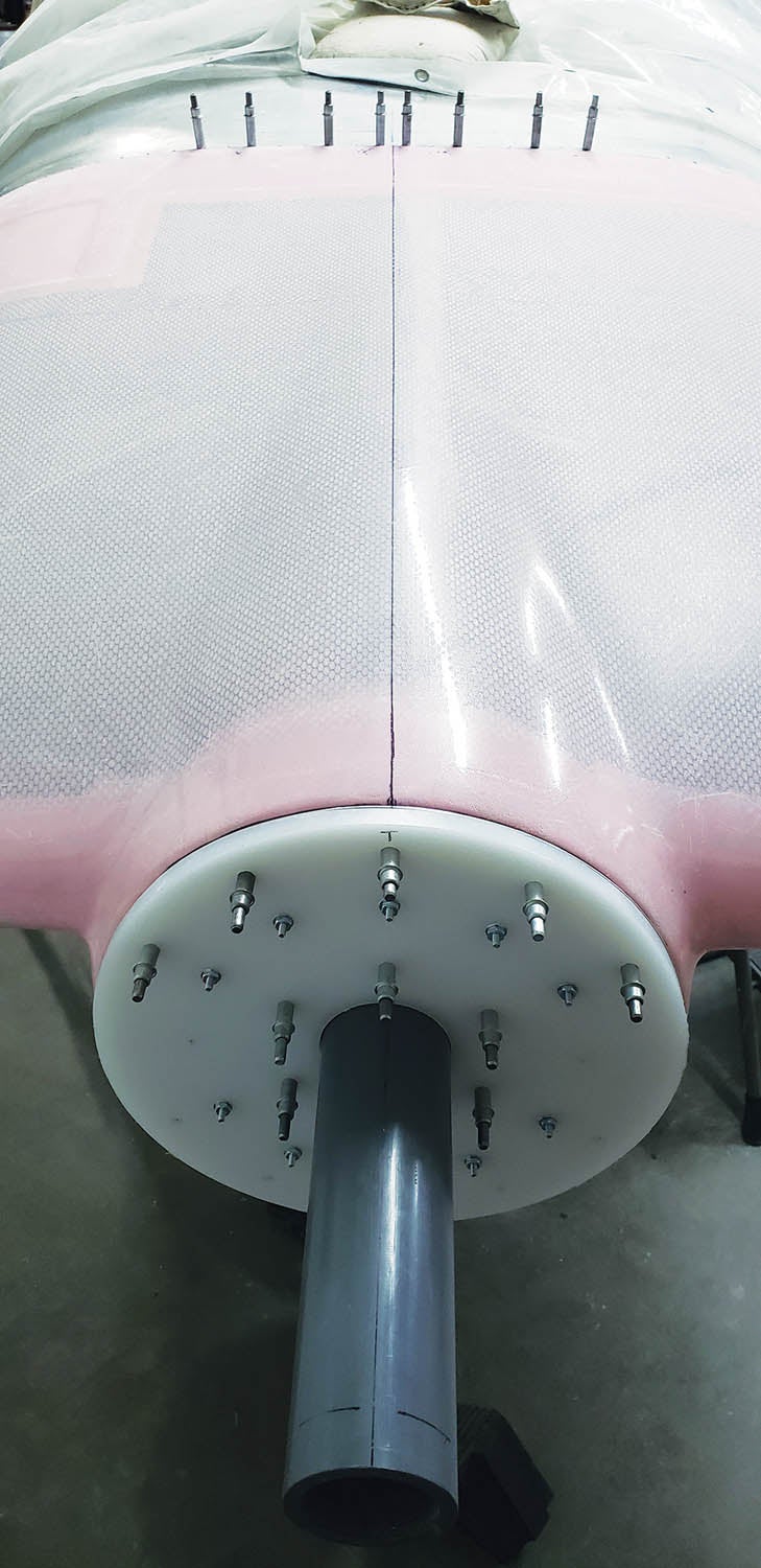
Tape the cowl halves together along the sides. Lay the nose bowl disc on the cowl nose bowl. Center the disc to the nose bowl top and bottom centerlines. If the horizon line matches up, consider yourself lucky and go buy a lotto. Make sure the TDC mark on the nose bowl disc is at the top with the pre-drawn centerline. That way it can be removed and replaced right where it was drilled. Align the horizon line as best you can, but don’t get crazy. Ideally, you want the disc centered and aligned to the top and bottom centerlines. Match drill the holes in the nose bowl disc to the cowl nose bowl and Cleco.
Step 7
Make eight strips approximately 1×3 inches from scrap aluminum. Drill four holes in each. These are useful for keeping the top and bottom cowl pieces together. Match drill a few to each side of the top cowl and add a couple of Clecoes. Leave the Clecoes attached to the top cowl for now. The bottom holes can be drilled later to Cleco the cowl halves together.
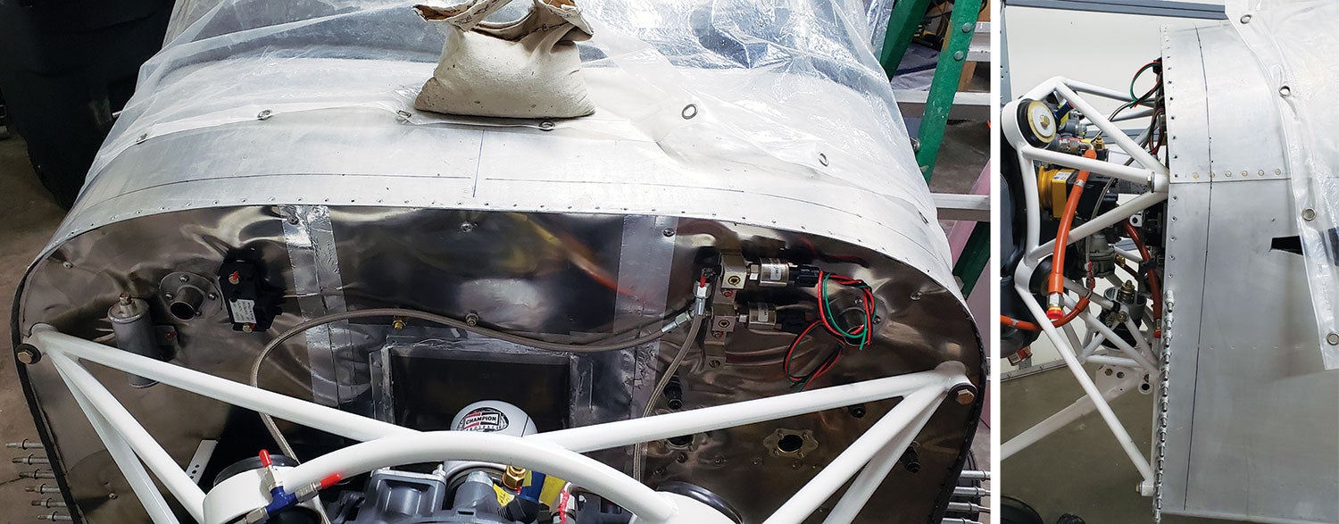
A few tabs attached to the firewall are handy so the cowl is flush with the top forward fuselage skin. I made some temporary flanges from scrap pieces of aluminum. Cleco them to the firewall along the top.
Step 8
We need a starting point to get the first cuts. Cleco the nose bowl disc to the top cowl nose bowl and slip the assembly over the EZ-COWL jig with the aft cowl edge over the firewall. Push the cowl back until the nose bowl disc contacts the bolt heads on the jig. It is now in the correct position, so tape the cowl to the skin.
Step 9
Measure from the 2-inch firewall reference line forward and make lots of tick marks. Connect the ticks. That’s our starting line to cut the cowl to match the firewall.
Remove the top cowl and transfer the nose bowl disc to the lower cowl. Repeat the process but get some help. The lower cowl will hit the gear strut. Center it using the marks on the nose bowl disc and jig and slide the cowl back until it makes contact with the strut. Center the aft edge as close as possible to the centerline of the fuse by using a straightedge. Mark the gear location. Then measure the remaining distance needed to allow the nose bowl disc to contact the bolt heads on the jig. The measurement is approximately how deep the relief needs to be cut to clear the gear.
Step 10
Remove the cowl. Draw the relief for the gear using the measurement, but cut less than measured and check. Repeat until the nose bowl disc touches the bolt heads on the jig and the cowl doesn’t hit the gear leg. Hold the cowl in place with a cargo strap then tape it to the skin. Repeat the measurements from the 2-inch reference line. Now we have a starting point to cut the firewall edge on both the top and bottom pieces of the cowl. Trim outside the line about 1/16 inch.
Step 11
We really need the firewall edge of the cowling to fit flush to the firewall, but don’t go too far. We will fine-tune it after the Skybolt flanges or hinges are installed. Skybolt provides a wonderful instruction book. It’s worth downloading and following. Much of what follows is from their instructions. I can’t take credit.
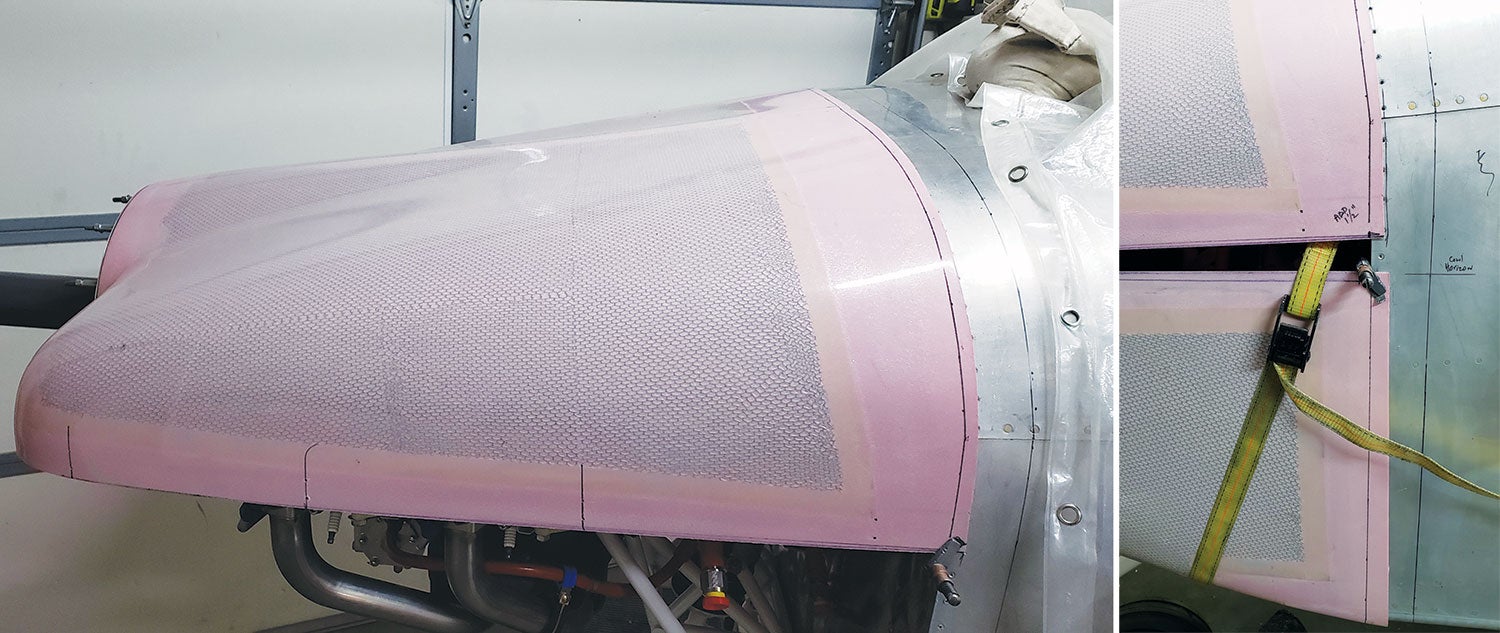
Trim the aft edge of both cowl halves a little at a time until each fits flush or extends a tiny bit past the firewall edge. The temporary flanges will help keep the cowl flush to the skin. The nose bowl disc should barely contact the bolt heads. Just get it close for now.
Step 12
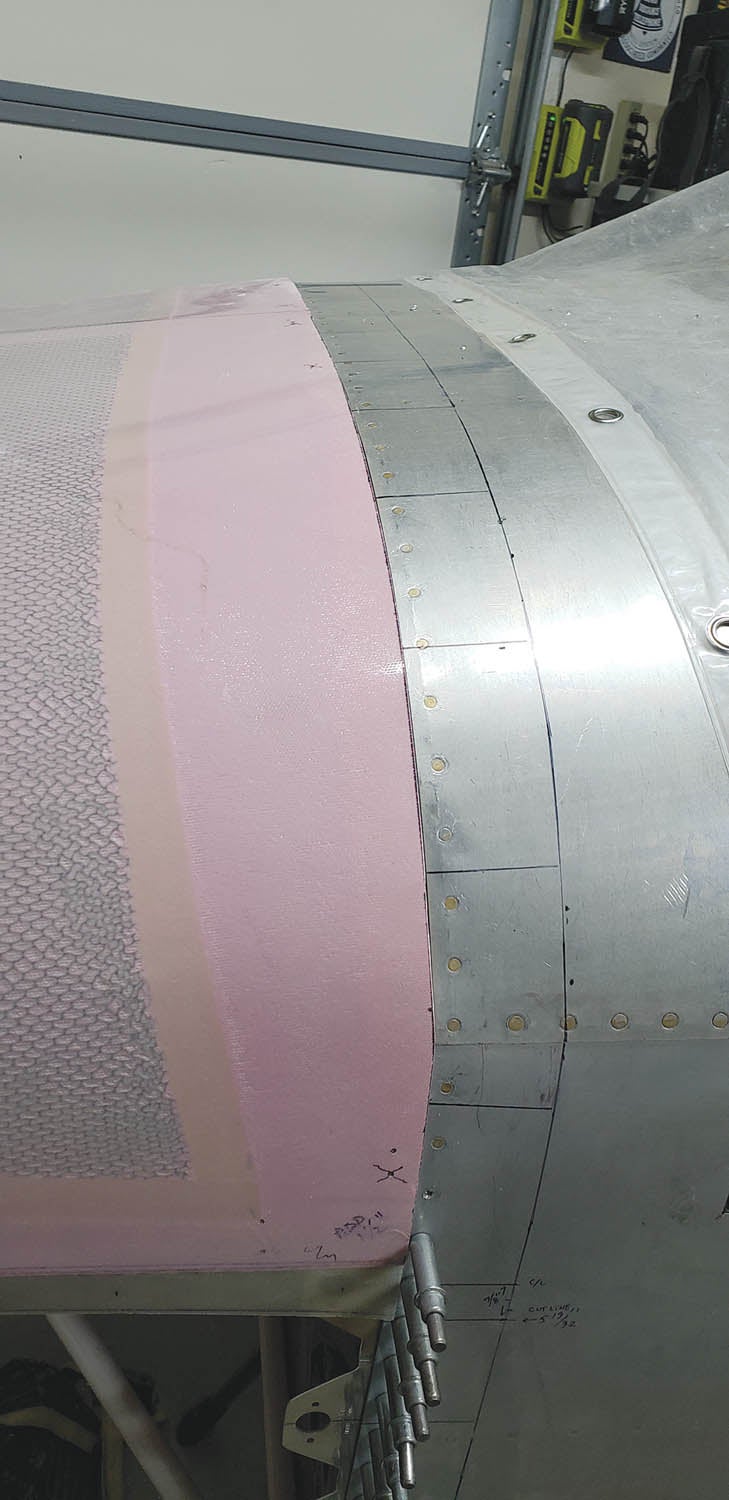
Next, we need a side-split reference line on the fuse. The top cowl should be flush or just a hair past the firewall and barely touching the bolts we set for the gap. If you trimmed too much and there are gaps, don’t sweat it. We can fill those during finishing and people will admire your precision.
Cleco the nose bowl disc to the top cowl and slip it into place as flush to the firewall as it will go. Use a level to set the forward nose bowl laterally level (roll). Double-check the fuse is still level. Verify the cowl is centered at the firewall. Drill one or two holes into the temporary firewall flanges to lock the cowl into this position. Cleco the top cowl. Cowl and fuse centerlines should be aligned. This is where it will live forever, so make it count.
Step 13
Double-check that the fuse is still level longitudinally (pitch). A helper and a long, flexible straightedge make this job easier. Position the forward end of the straightedge at the nose bowl forward horizon line edge. Either the left or right corner near the inlet works fine. Level the straightedge perfectly. Clamp it if possible. Mark that reference line on the fuselage side skin. Repeat on the opposite side. Remove the top cowl. That’s the reference cut line for both upper and lower cowls, and it should be longitudinally (pitch) aligned with the longerons.
If you are precise, both side reference marks should fall exactly in the same place on both sides. If not, I doubt anyone will notice but it’s worth double-checking. They should fall pretty close to the same location on each side. Mine were so close I duplicated the location on each side of the fuse.
Step 14
Now that we have both cowls sort of fitting at the firewall and a horizon line on both sides of the fuse, we can move on to the fasteners. We don’t want to cut the split line until we can lock the cowl into position so let’s install the flanges for Skybolt fasteners. If you plan to use hinges, you’ll probably want to review a bunch of builder logs for tips and tricks. Sorry, I’m not much help. But here’s the bottom line: Whatever type of fasteners you use, you need to lock the cowl positions before cutting that split along the sides.
Step 15
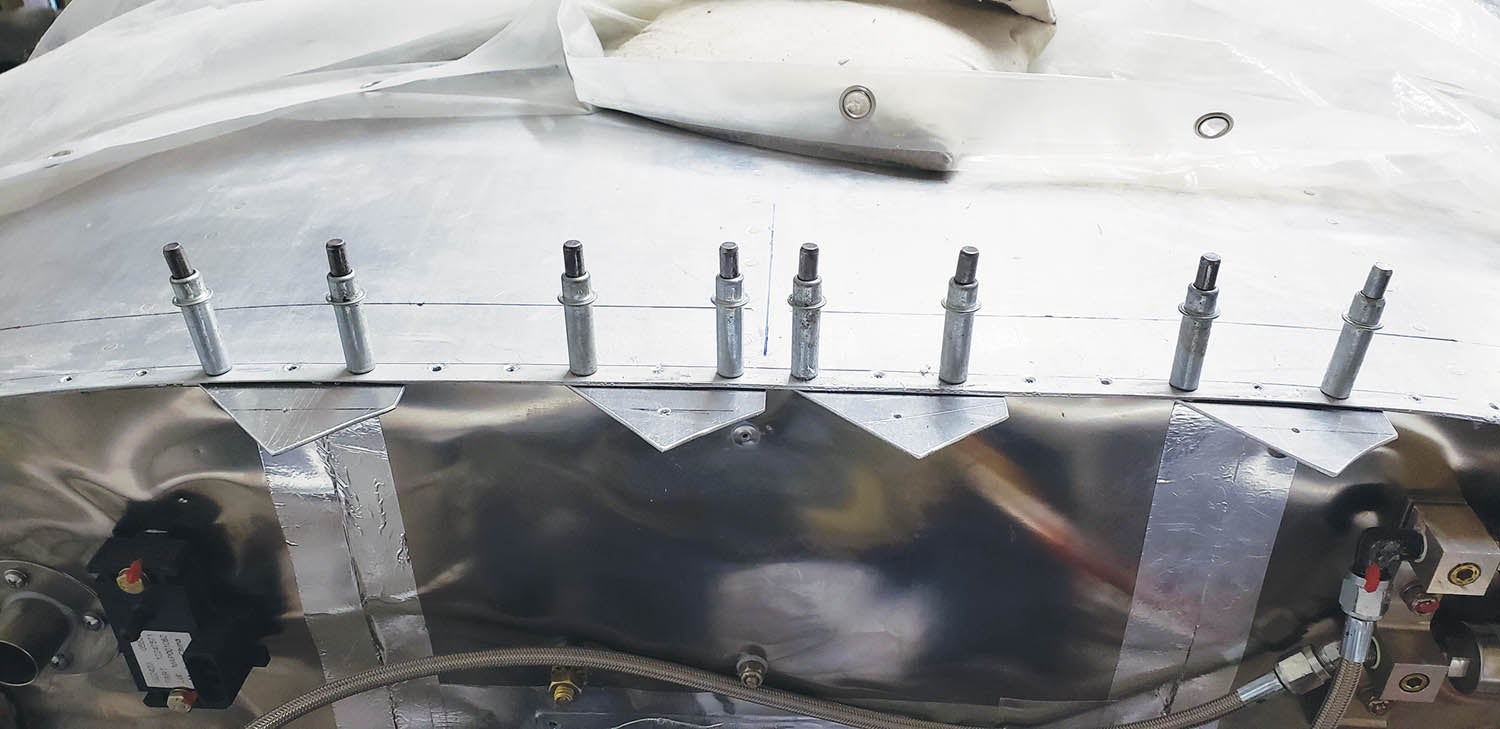
Let’s install the Skybolt flanges and fasteners. There should be a cowl split line on either side of the fuse side skin. There should also be a top skin centerline. Measure and verify that they are accurate. Once the Skybolt flanges are drilled, there’s no going back.
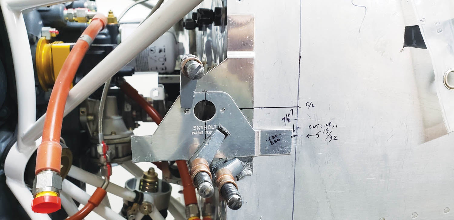
Skybolt suggests locating the firewall fastener nearest the split line so it is in line with the fasteners along the split. Makes sense. Looks nice. Skybolt provides Cleco bushings that make this job much easier. Mark the vertical centerline on all the Skybolt flanges. Grab two flanges. Slip a Cleco bushing into each and a long AN470 rivet to hold the two flange holes centered. Rotate the two flanges until they are perpendicular to each other and clamp them together.
Skybolt instructions call for the upper horizontal edge of the flanges to fall 0.230 to 0.250 inch above the split line. Mark the firewall flange or skin and position the stack accordingly, then clamp it to the firewall flange in that location.
Step 16
Make a mark indicating the Skybolt fastener centerline on the fuse skin. That’s the first Skybolt flange location and the starting point for measuring the location of the fasteners toward the top. Repeat on the opposite side. Skybolts are designed with 31/2-inch spacing. You can change it, but you will need to cut flanges. I fabricated a plenum so the pressure inside the cowl should be fine. Those of you using baffle seals might consider closer spacing to avoid bulging between fasteners.
Next, measure 31/2 inches from the first fastener centerline and mark. Repeat to the top. Each is the center of a flange. The top center fastener will land dead center. Double-check all the measurements. The center flange and the flanges either side of it will probably need tabs cut to fit. Start with the center flange. Make sure it’s flush to the firewall. There should be about 1/4 inch of the tabs exposed.
Centerlines should be aligned. Clamp. Match drill the firewall holes into the flange. Cleco. Working down toward the split, clamp, drill, Cleco, repeat. Some flanges need to be shaped to match the curve. Some may need the tab trimmed a little if the flanges overlap or a rivet hole edge distance is too small.
Step 17
Repeat on the opposite side. Starting at one end, remove a flange, countersink for the firewall dimples and countersink for the fastener flush rivets. Cleco the flanges back in place and label each one. They should all be ready for final prep (alodine or primer) and riveting.
Step 18
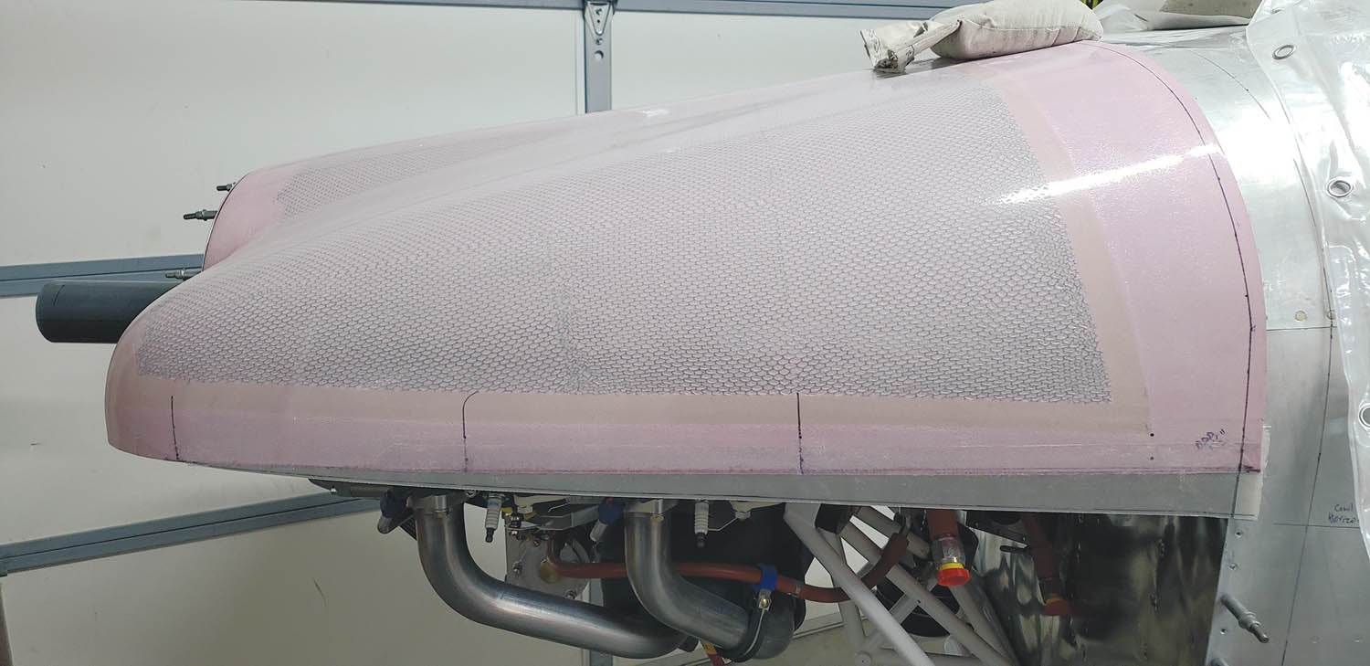
You may want a shim to adjust the fit of the cowl edge thickness. Consider beefing up the edges of the cowls with a strip of carbon fiber covered with a strip of fiberglass maybe 1 inch wide on all the inside edges. Fabricate a shim strip the required thickness to adjust for this slightly thicker edge. My shim strip was 0.032-inch thick. This allows the cowl to sit flush to the fuse skins. Label the flanges and shim strips. They are all unique and it makes a very difficult puzzle trying to get them back where they belong.
Step 19
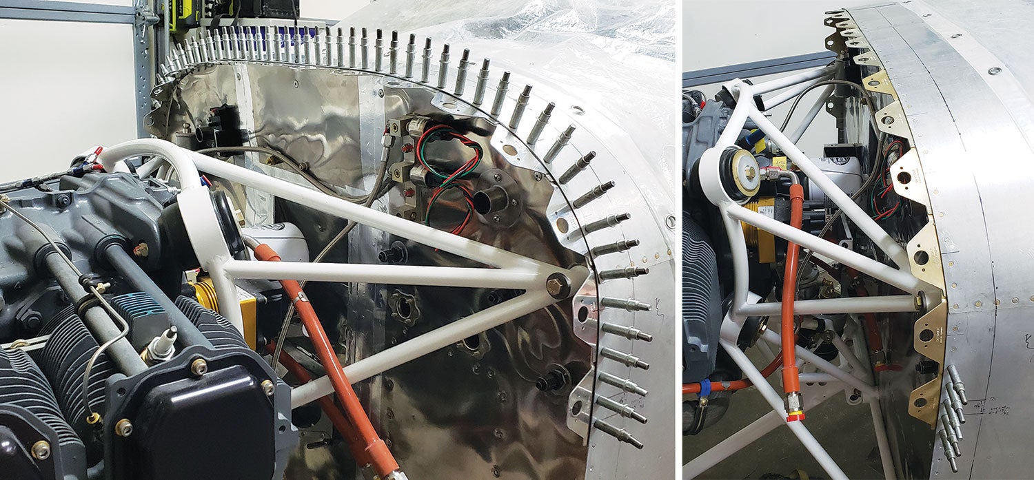
Move on to the bottom cowl firewall Skybolt flanges. Start with the lower engine mount and measure both up and inboard. Pay attention to any interference with the engine mount and receptacles. Ideally, they should be the same spacing, but the engine mount may force some adjustment to the locations. Same for the lower area. Do your best. I used 3-inch spacing at the bottom, resulting in four fasteners on each side. Van’s recommends screws and fasteners at the cowl exit. Check your plans.
Step 20
Remember the shim strip(s)? Rivet all the flanges and shim strips in place. Once the flanges on the firewall are done, we can move on to drilling the cowl for the firewall fasteners.
Step 21
Now is a good time to fine-tune that cowl edge at the firewall. Slip the top cowl in place using the jig. If it needs a tiny bit here or there, use a fine marker to draw a line right along the edge where material needs to be removed. Remove and block sand with 40 grit until the line is removed. Repeat until it butts right up to the firewall edge with the jig contacting the bolt heads. You can fine tune the fit for a paint gap later.
That’s all for now. In the next installment, we’ll begin to drill some holes for the Skybolt fasteners. Thanks for tuning in. I’ll see ya when I see ya.