 Time to start the Cowl? It’s one of the biggest milestones and ranks right up there with the canopy. Don’t fret. There are tips and tricks to make it a little less painful.
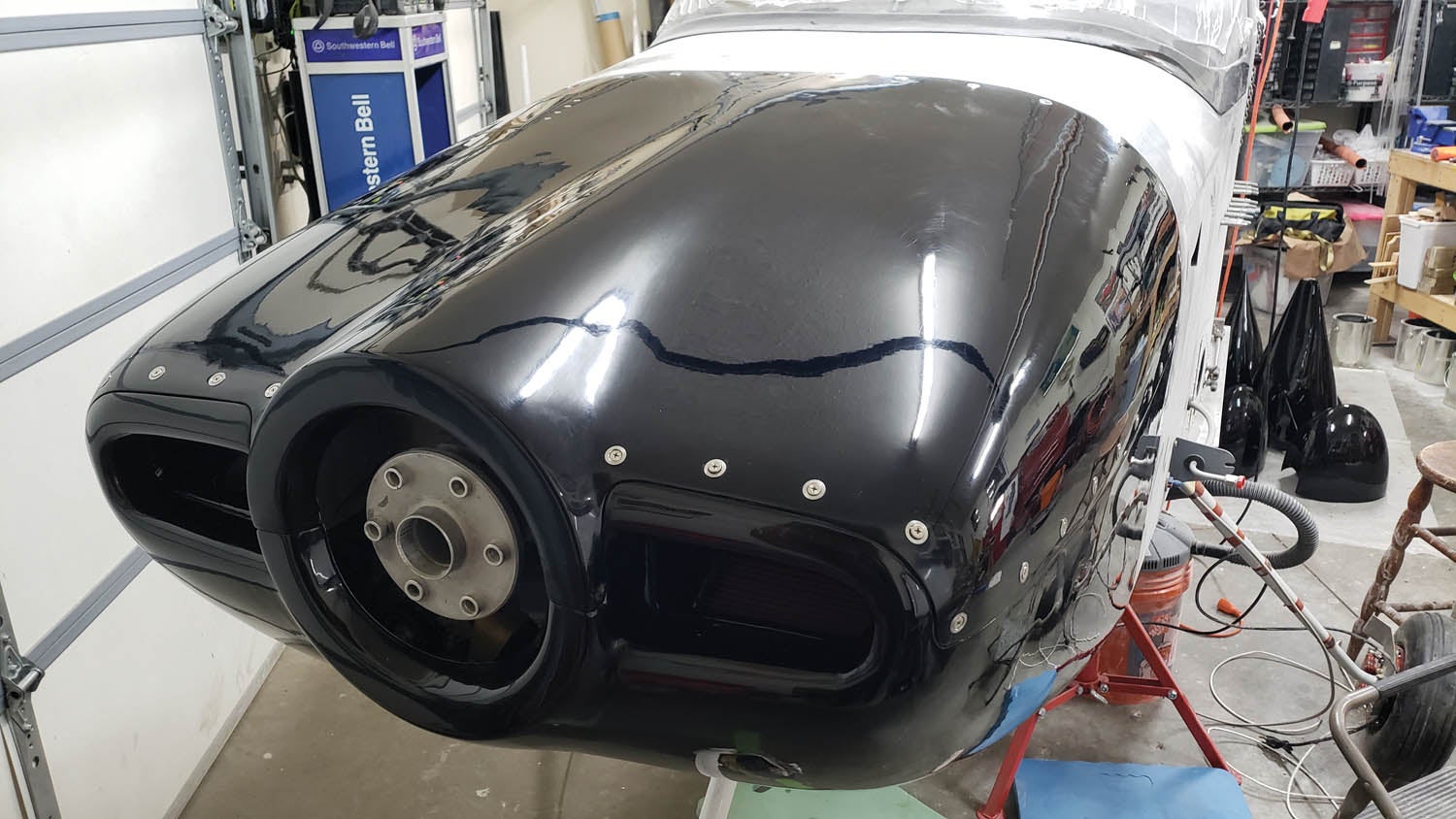
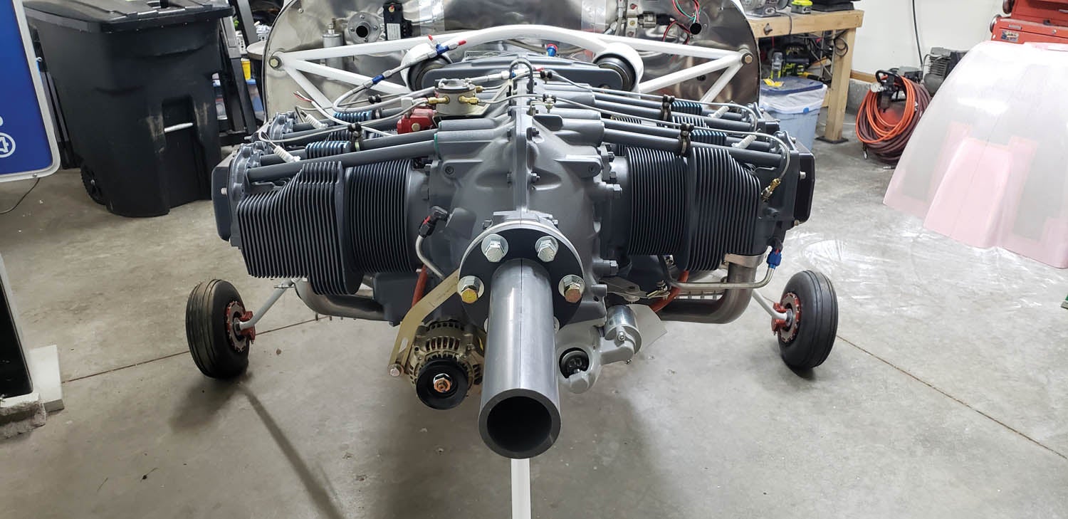
My mentor, Dave Paule, tipped me off to a neat jig designed by David Howe. David fabricates a bunch of cool RV gadgets, and his EZ-COWL jig is a very useful tool. It functions as an extension of the engine crankshaft, making it easy to set up the cowl perfectly aligned on the engine thrust line. It also holds the cowl in position to make trimming much easier. I highly recommend it!
For the price of shipping, David will send you an EZ-COWL jig, provided you pass it along to a fellow builder when you’re done using it (see sidebar below). You can also rent a jig from Flyboy Accessories. The third option is to build your own. David was kind enough to share his plans and gave me permission to use them. They allow builders to fabricate the jig using standard tools.
The jig is mostly made from PVC Schedule 80 pipe and 1/2-inch-thick PVC sheet. According to David, “The beauty of Schedule 80 pipe is that the inner diameter is 2.29 inches, approximately 0.040 inch larger than a Lycoming Type 2 crankshaft pilot, which is 2.25 inches. To get a perfect fit, you can shim the pilot with masking or Gorilla tape.” He also notes that “PVC is very easy to machine and plenty tough for this job.”
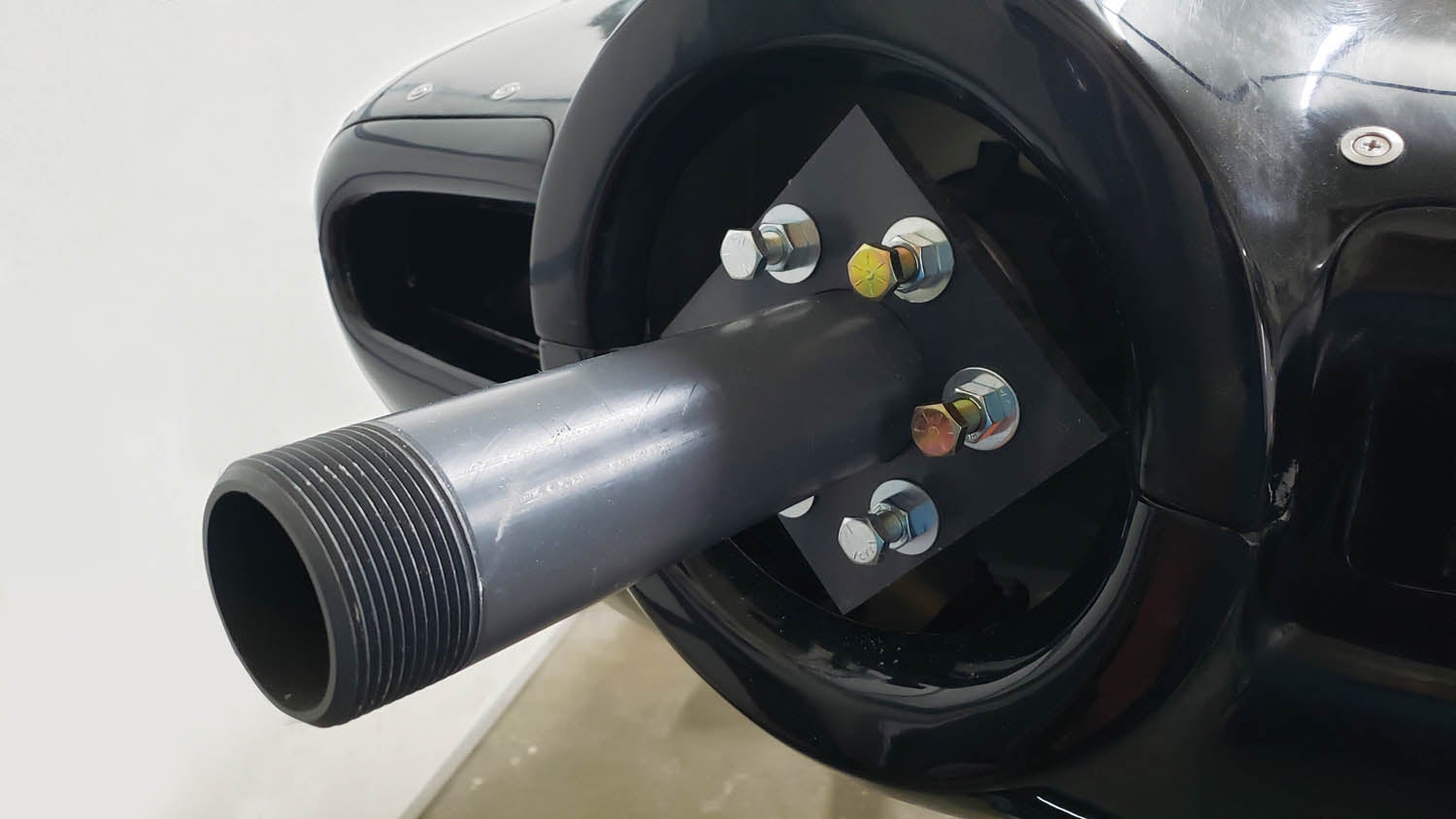
The smallest section of straight 2-1/2-inch Schedule 80 PVC I could find was a 12-inch nipple from Grainger. It is threaded on one end, but that won’t matter. The nipple is easy to use as it does not need to be cut and the end is square. The hole for the pipe doesn’t have to be precise but it helps.
A critical part of the jig is the flat flange. The pipe has to be bonded square to the flat section or there will be some runout and the cowl could end up off-center. I made the flange from 1/2-inch PVC sheet, but almost anything flat will suffice, including 3/4-inch plywood. Ultimately, the bonding is what matters.
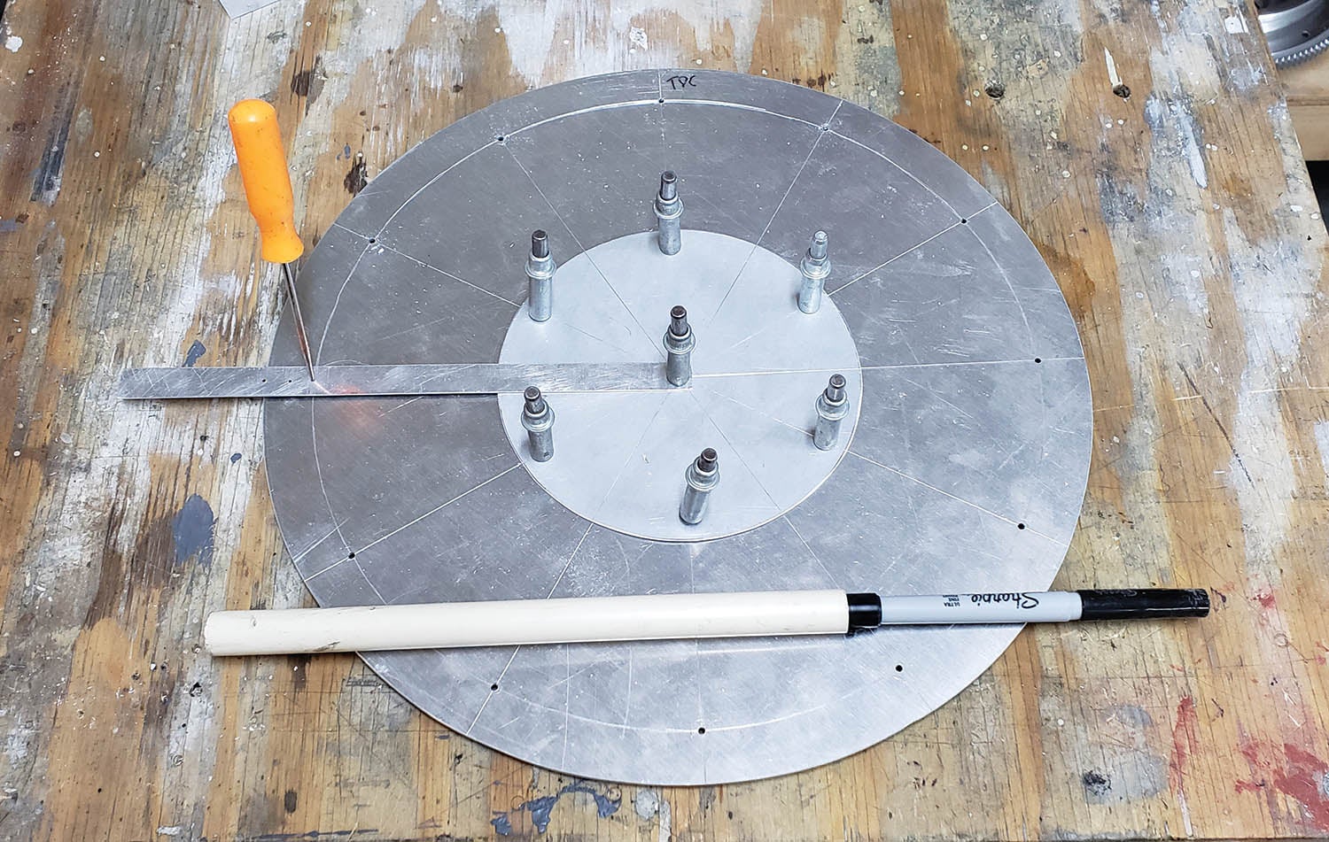
One part of the jig is made from aluminum: the nose bowl disc. It is the same diameter as the spinner and is used to center the cowl (either together or halves) on the crankshaft. Once the disc is temporarily installed on the cowl, it can slide over the pipe mounted to the crank flange, giving perfect alignment each time it is reinstalled.
Let’s get started with a parts list, followed by step-by-step instructions for building an EZ-COWL jig.
- Schedule 80 PVC nipple: 2-1/2-inch nominal pipe size, 12-inch overall length, threaded on one end.
- PVC sheet: 1/2-inch thick, 12 inches wide x 12 inches long, gray, opaque, 8350 psi tensile strength.
- West Systems G-Flex Epoxy
- Six 1/2-inch x 20 bolts (lengths to be determined in Step 29)
- Six 1/2-inch x 20 nuts
- Six 1/2-inch flat washers
- One 14×14-inch piece of 0.040- or 0.063-inch aluminum
- One HDPE cutting board (stolen from my wife’s kitchen)
Step 1
Make sure your engine is at top dead center (TDC). If it’s not, get it there. Sorry, it’s my OCD kicking in. I like things to go back together the way they came apart.
Step 2
Mark the flywheel and flange. Remove the flywheel. Mark the crank flange in relation to the case at TDC.
Step 3
Refer to the plans and a template called Cowl Jig Version 2 (page 1). You can download the PDF files here.
Step 4
Print the Cowl Jig Version 2 template and verify the dimensions match the print.
Step 5
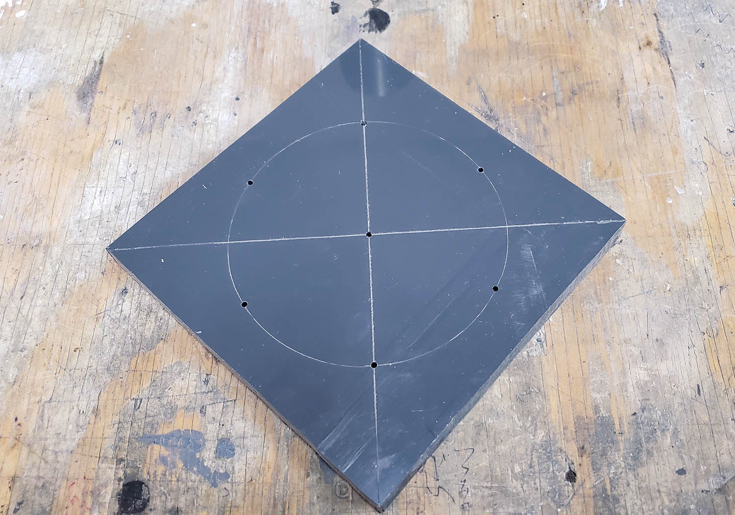
Cut a 6×6-inch piece from the big sheet of flat PVC. Mark a center point on the 6×6-inch piece. It’s square so just connect the corners. The intersection is the center.
Step 6
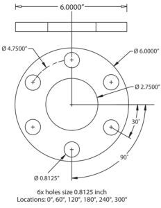
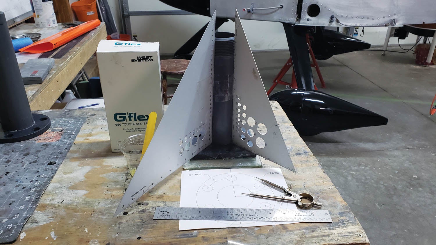
Use a compass to scribe a circle 23/8 inches from center. Use the template to set the compass. The scribed circle is where the crankshaft prop flange lug holes will be located. Check yours to be certain of the dimension and scribe accordingly.
Step 7
Scribe another circle aligned to the 6-inch edge. That will give you a nice round piece. The outer round shape is optional; the square shape works just fine.
Step 8
Two holes should already be located along one of the center lines. The other four can be located using the template. Lay the template on the flat piece of PVC and align the center of the drawing with the center of the part. Rotate the drawing until the line on the drawing and two predetermined holes are in alignment to the line on the part. Tape the drawing in place.
Step 9
Center punch the six hole locations through the template. Drill the center hole and six flange holes #40.
Step 10
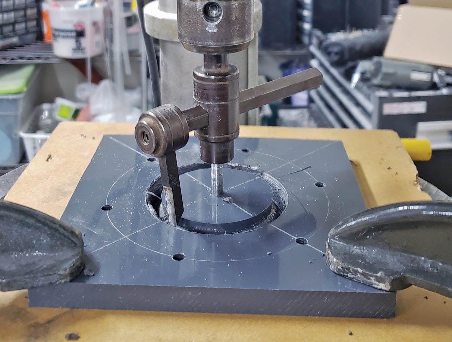
Enlarge the center hole to 1/4 inch. Measure your pipe. They vary a little. A fly cutter works pretty well, but a hole saw will also work. If neither is available, cut with a jigsaw by drilling a pilot hole first.
Use a 1/4-inch rod in the fly cutter or hole saw so it won’t wander. Bore the hole for the pipe. Make some practice cuts on scrap to verify the dimension for the pipe is correct. Work slow and allow the material to cool.
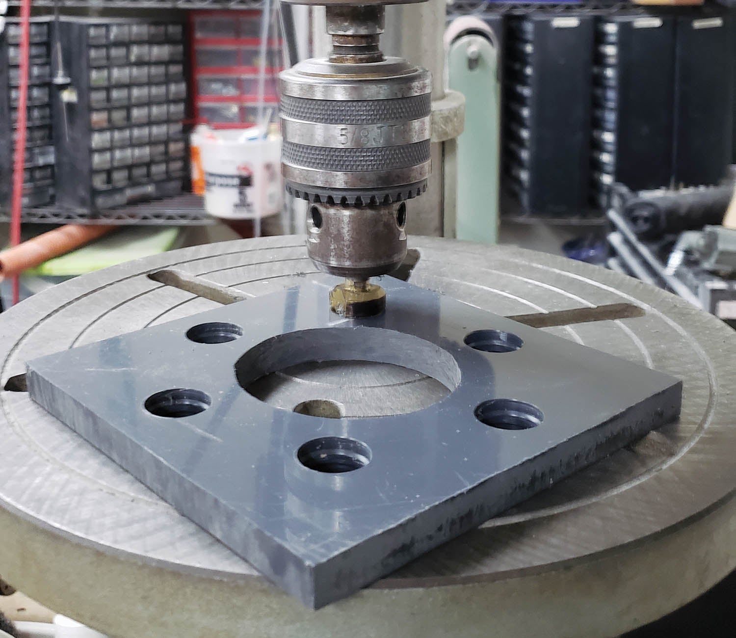
Step 11
Enlarge the six holes to match the diameter of the prop flange lugs. Size is not critical. A step drill works fine and it’s OK if the holes are slightly too big.

Step 12
Time to glue stuff together. Use a nice flat work surface. A piece of glass from an old photo frame will work. What really matters is that the pipe is square to the flange. We need a nice flat surface so the pipe doesn’t protrude past the flange.
G-Flex is very tenacious. Use a piece of 4-mil plastic, wax paper or apply some 3M Heavy Duty Shipping Tape to the bottom side of the jig flange and to the top of the glass or work surface. Wax the material. You don’t want the epoxy to stick. Yes, I found out the hard way—G-Flex will stick to waxed glass.
Step 13
Use a couple of builder squares offset 90° from each other to verify the pipe is square to the flange. We want it as accurate as possible. Let everything cure, and the jig is ready to go.
Step 14
You’ll need six 1/2-inch x 20 bolts, nuts and washers. The length of the bolts is based on the desired gap. We will do some math later. For now, let’s see how this all goes together.
Step 15
Place the jig on the crank flange and check it fits flush. You may have to chamfer the inner edge of the pipe to clear the prop flange weld. Transfer the TDC mark to the flange on the jig. It’s just a reference used to put the jig back on later. Set the jig aside for now.
Step 16
The nose bowl disc diameter is important! It needs to be the same diameter as the cowl nose bowl and spinner flange. If you’re building an RV-7/7A, it’s probably 13 inches.
The nose bowl disc functions as a plate to hold the nose bowl of the cowl halves together flush. It also allows the assembly to be positioned and locked to the center of the crankshaft.
Step 17
Next, cut the nose bowl disc. Either 0.040- or 0.063-inch aluminum is thick enough so it doesn’t flex too much.
Cut the aluminum 14×14 inches wide. Scribe center lines from corner to corner and side to side exactly one-half the width in both directions. Scribe lines are OK because the nose bowl disc won’t be structural, and we don’t want the markings rubbing off.
Step 18
Center punch the intersection precisely, then drill the center hole #41.
Step 19
To scribe a large circle, we need a big compass. If you don’t have one, make one. Use a strip of scrap aluminum with a #41 hole on one end and a tiny hole for the scribe at the desired radius. The distance between centers is 6-1/2 inches for a 13-inch circle.
Step 20
Cleco the homemade compass to the center hole and scribe the outer diameter for the 13-inch circle. Repeat with a 5-3/4-inch radius for an inner 11-1/2-inch circle. The inner circle will serve as a line for later use to locate the holes drilled into the cowl nose bowl.
Step 21
Now cut the center hole in the nose bowl disc. It needs to fit the cowl jig PVC pipe precisely.
Enlarge the center pilot hole to 1/4 inch and use the fly cutter again to bore the hole, matching the diameter of the cowl jig PVC pipe. It needs to be right, so take some time and make some practice cuts on scrap until you get the diameter perfect. You want the nose bowl disc to slide on with no slop.
Step 22
Cut the outer 13-inch circle outside the line and sand or file it to the line. You should have a 13-inch doughnut exactly the dimension of the spinner bulkhead, with a center hole to fit over the PVC pipe.
Step 23
The nose bowl disc is almost ready to use, but you need to add some pilot holes to match drill the forward nose bowl of the cowl. I drilled a set of #41 pilot holes using the intersections of the 11-1/2-inch inner circle and the scribed lines. Four or five holes along the top and bottom halves will suffice.
Step 24
I added a piece of HDPE to the nose bowl disc to make it stiffer. (This step is optional.) Cheap cutting boards are made of HDPE. This one is big enough that some will be left to give your spouse a nice cutting board.
Step 25
Use the same techniques previously used to scribe lines and drill holes. The HDPE is just a stiffener so it doesn’t have to be a close tolerance fit to the jig.
Step 26
Drill some holes for screws and assemble the nose bowl disc to the HDPE. Make sure the hardware won’t hit the flange spacer bolts. The holes for the Clecoes to the cowl nose bowl will have to be enlarged to clear the Clecoes. (Disregard the inner set of Clecoes in the photo; the version I used had a two-piece nose bowl disc.)
Step 27
Next up is mounting the jig. Check your prop drawing carefully. Look for the gap dimension between the spinner and cowl. The spinner-cowl gap will vary with the prop manufacturer and personal preference. Call the manufacturer and ask. Too narrow and the spinner may contact the cowl when the engine shakes.
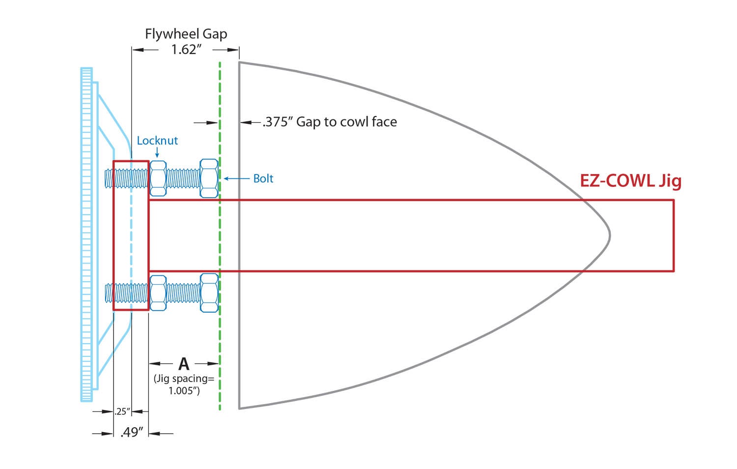
Here’s the formula I used to calculate the dimension to set the jig bolts. The starting dimension (provided by the prop manufacturer) is from the back of the spinner to the face of the flywheel. The formula calculates the distance from the jig face to the bolt head. When the cowl is positioned over the jig, the nose bowl disc will touch the bolt heads, and the cowl nose bowl will be in the correct position to ensure a uniform spinner-to-cowl gap.
A (jig spacing) =
Prop spinner to flywheel gap (1.62 inch)
+ Flywheel thickness (0.250 inch)
– Jig thickness (0.490 inch)
– Spinner to cowl gap (0.375 inch)
(Note: There are other ways to locate this position, but this worked for me. David uses a different method in the instructions that come with his jig.)
Step 28
The flywheel is removed for convenience, so remember the thickness. (Mine is 0.250 inch thick). Do the math and figure out the distance from the forward side of the jig face to the aft side of the nose bowl disc. My distance, planning for a 3/8-inch spinner-to-cowl gap, worked out to 1.005 inch.
Whirl Wind Propellers recommended the 3/8-inch space to accommodate engine vibration. The space can be easily adjusted with filler, but it’s much more difficult to increase the gap, so consider this carefully.
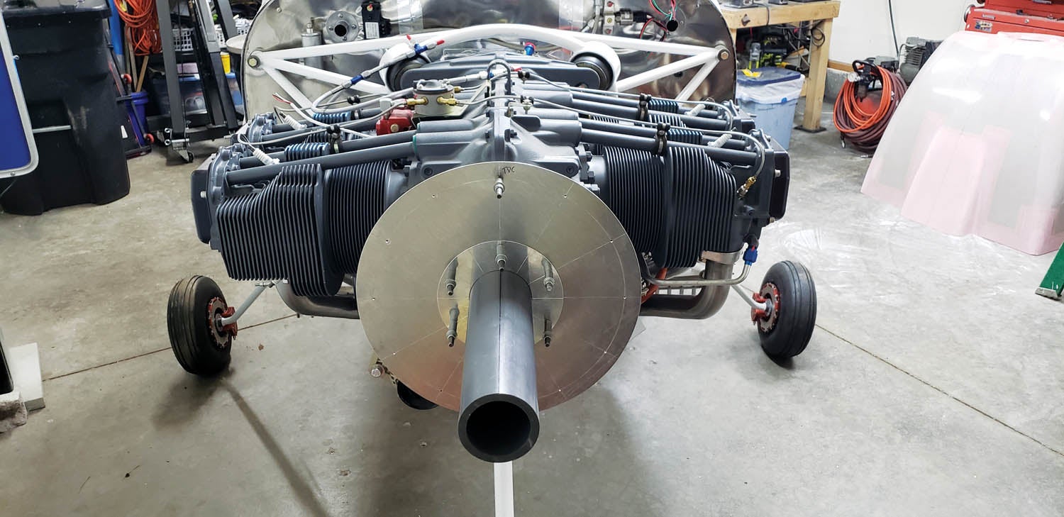
Step 29
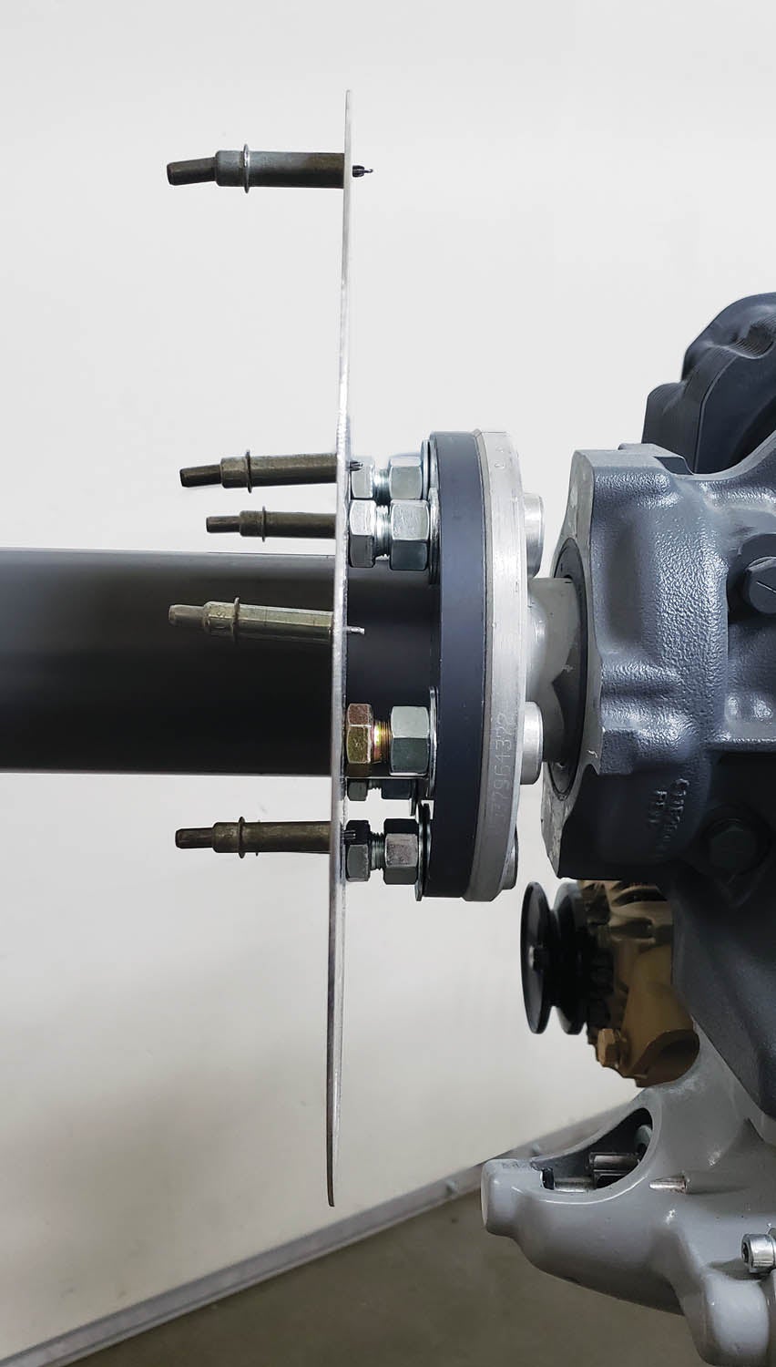
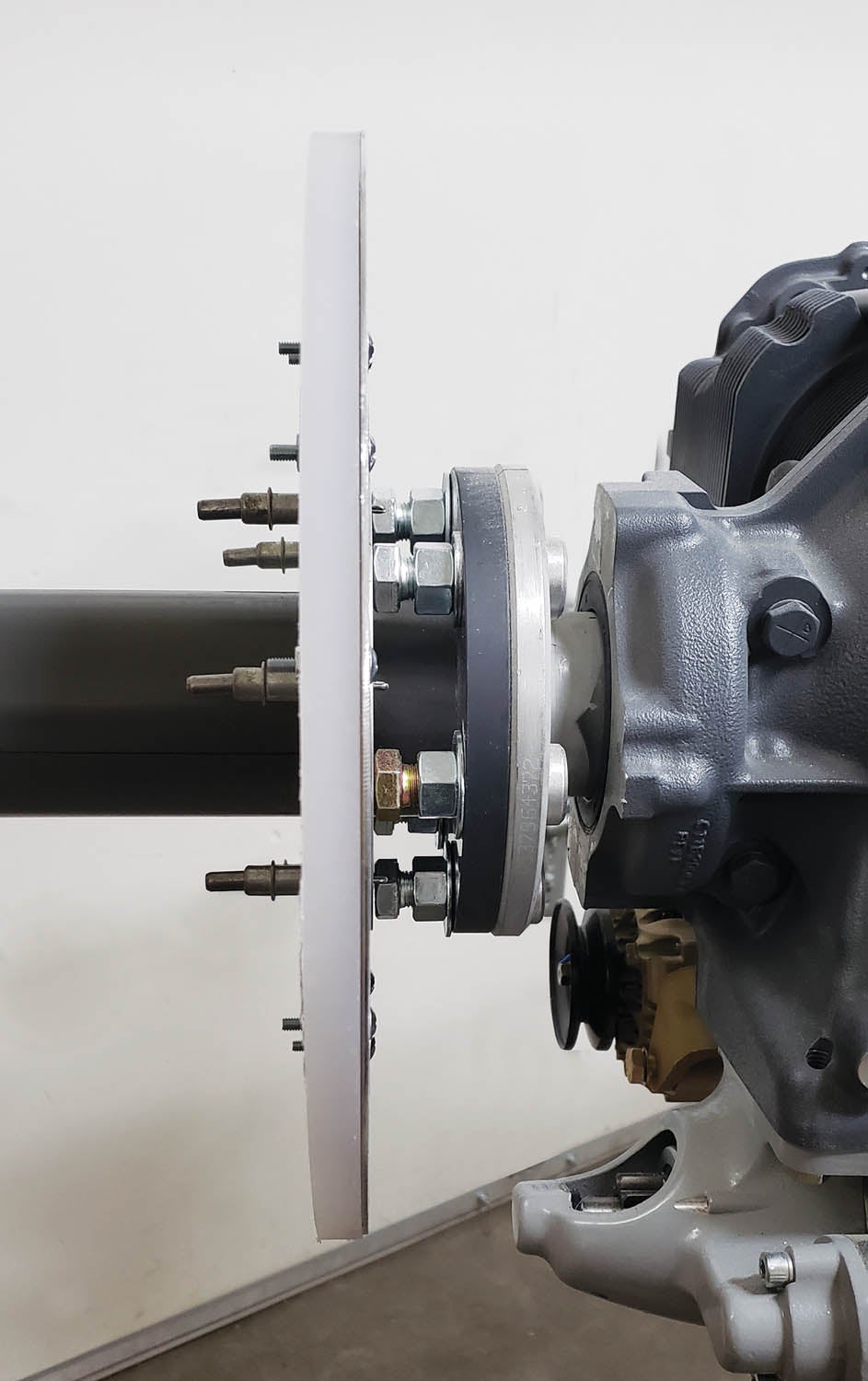
Remember the bolts we needed to bolt the jig to the crankshaft? Here’s where the length of the bolts becomes important. Spin a nut and washer on each of the six bolts. Install the cowl jig with the bolts. Set the bolt heads so the surfaces of the bolt heads are exactly the correct distance from the jig face—1 inch was close enough for mine.
Step 30
Tighten the nuts to lock them in place. Double-check to be sure they’re tight. It takes some tweaking, but when you’re done the nose bowl disc will contact the bolt heads, setting the exact space for the cowl nose bowl.
Step 31
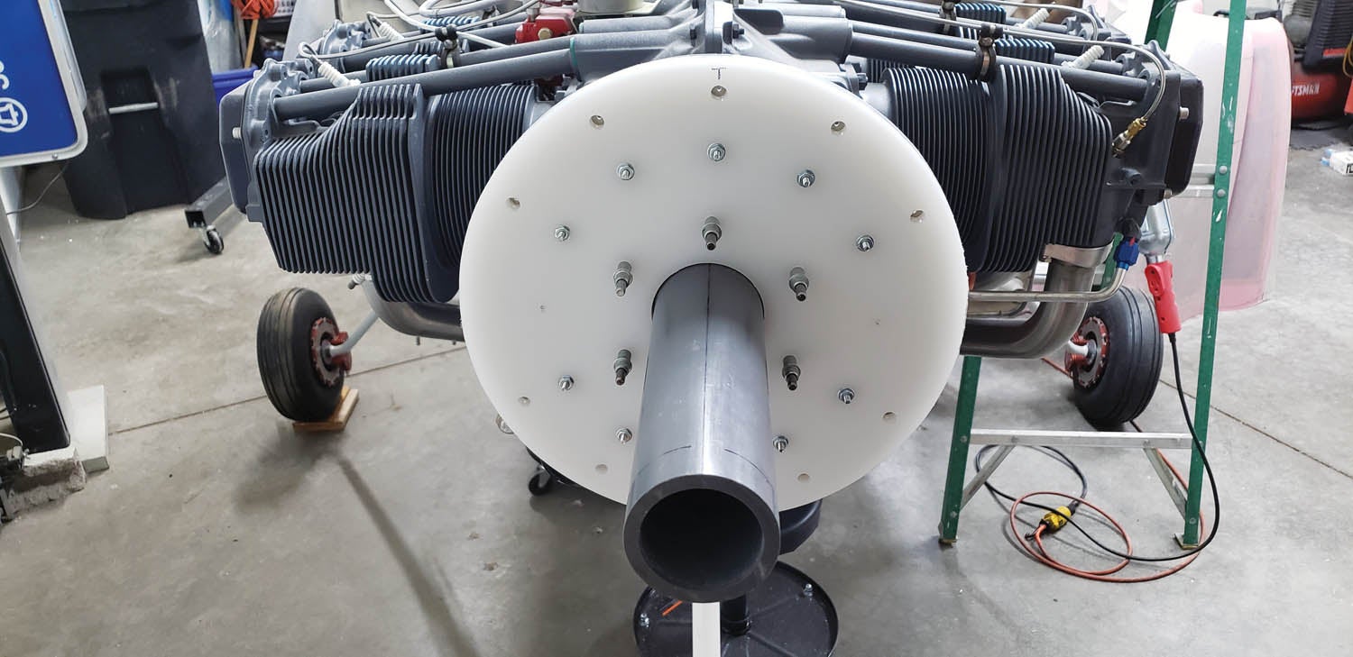
Slip the cowl nose bowl on the cowl jig. Align it so the Clecoes fall between bolts. The plate should be in contact with the bolt heads.
Step 32
Mark the top TDC, so it can go back to the same place. It’s now time to put the cowl together, which we’ll do in Part 2 of this article.
Thanks for tuning in. I’ll see ya when I see ya.


![[Credit: JetStream Rider]](https://www.kitplanes.com/wp-content/uploads/2026/04/AdobeStock_345999332.jpg?w=324&h=160&crop=1 "2026 Avionics and Lights Buyer’s Guide")


Great article and timing! I’m at this stage of my build.
One thing I noticed on the template I downloaded: Printing at 100% on my laser printer gave me some differing measurements:
The 6″ gauge across the top measured 6 1/8″
But the circle diameters were right on: 2 3/4″, 4 3/4″ and 9″
Are others seeing the same thing? I’m thinking ther gauge across the top needs to be tweeked in the drawing.
Thanks!
Russ
Oops, I meant the 6″ gauge is actually 5 7/8″ and the larger circle diameter measures 6″, not 9″
The outer ring (6″) doesn’t matter. You can even leave it square. Notice one of the photos.
Try and get the circle corresponding to the prop hub bolts close to actual dimension. Hold the template over your crankshaft hub and see if it’s close. Ideally, the six holes should be close, but they can be over size if necessary. They just need to clear the hub bushings.
As long as you have a center point the inner hole for the pipe can be bored to the OD of the pipe. The ID of the pipe is what centers the jig so even the center hole can be a little oversize.
Best of luck.
Thanks for the additinaly information. Yep, the hub dimension on the printout are correct. It’s just the 6″ calibration box at the top that’s off. Might confuse people.
Thanks again!
Russ
We did it the other way.
I had purchased a series of prop spacers on eBay years ago and machined one down to the length we needed to make the prop spinner spacing work.
Hey Larry! When’s Part 2 coming out? I’m looking forward to it.
Jeff
My camera ready art has a date of April 2023. Should be soon! There’s also a Part 3. Hope you enjoy. Thanks for tuning in. See ya when I see ya.
LL
Would be great to know the brand and specs of the “fly cutter” you used. I am building a RV 10.
Ava.
Sorry. It’s a dinosaur from a previous owner and build but it looks just like this one.
https://www.acehardware.com/departments/tools/power-tool-accessories/hole-saws/26339?store=08780&gclid=CjwKCAjwxr2iBhBJEiwAdXECw92AiH2yEDCa2CmJhuKJjE01u4ScgvyruWetdPQ-uth3Lty3ZsLh5xoC8N0QAvD_BwE&gclsrc=aw.ds
Comments are closed.