A press fit, also known as an interference fit, is the preferred ways to assemble hubs to shafts when concentricity, balance, and security are critical, or when other means, such as bolting or welding, are less than practical.
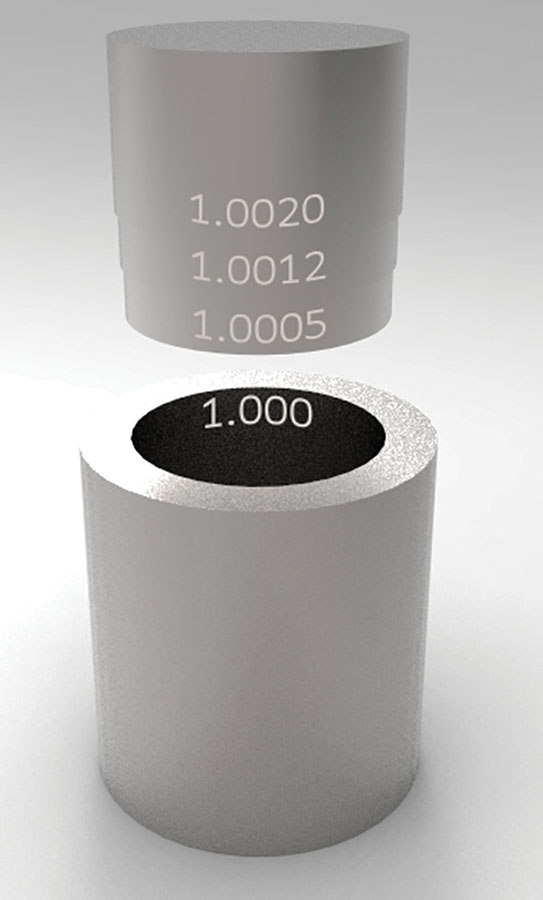
Depending on the class of fit, from a “light drive fit” to a “heavy” or “force fit,” the interference (the difference in diameter of the shaft, or the larger diameter, being pressed into a hole or bore, the smaller diameter) is typically between 0.0005 inch of interference per inch diameter, to about 0.0020 inch of interference per inch diameter.
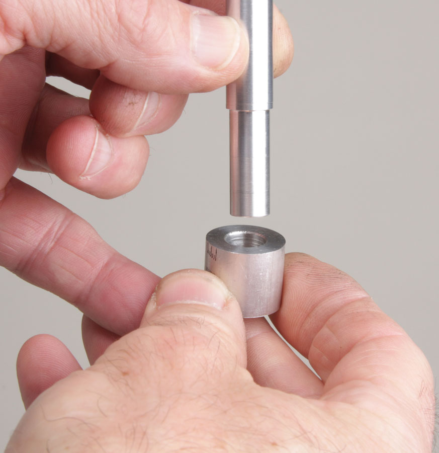
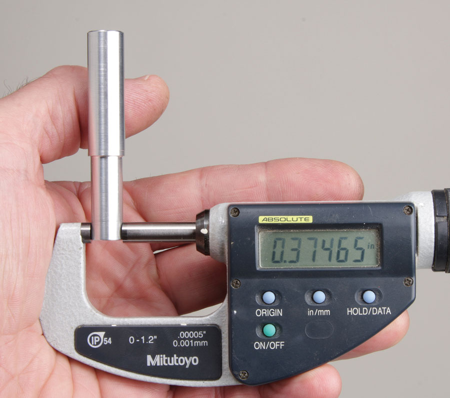
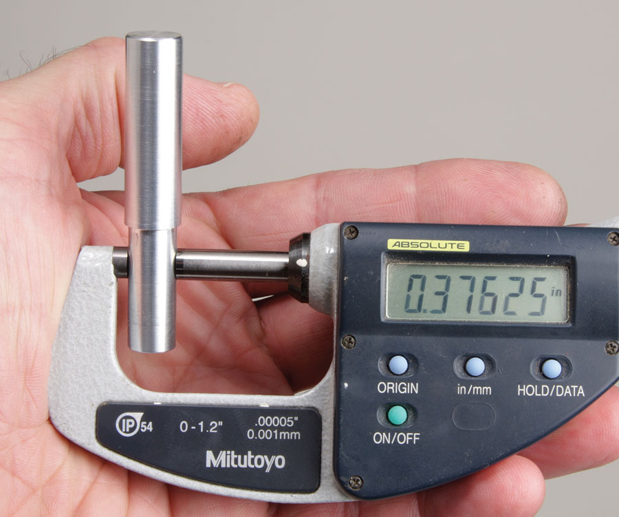
The task: Press this shaft onto this hub, which is a section of 3/4-inch-diameter aluminum with a 3/8-inch hole drilled in the center. Since a 3/8-inch drill doesn’t exactly drill a 0.375-inch-diameter hole, a way is needed to accurately gauge the true diameter.
When delving into machining operations like press fits, or any work that requires accuracy better than 0.001 inch, everyday calipers and micrometers are often not accurate enough. A way to overcome this, at least with interference fits, is to machine a go/no-go gauge right into the workpiece.
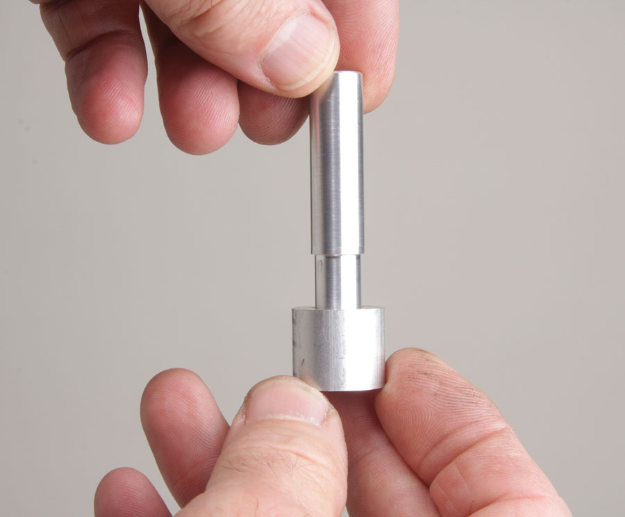
The trick is to lathe turn the shaft 1-1/2 to 2 times longer than necessary, then machine a short step (the first of what will be a series of steps) until it just slips over the hub bore. Then turn the next step 0.001-inch diameter larger and check the fit. If the hub still slips over the step, turn yet another step, and so on, until you reach the point where the hub no longer fits. You should measure the steps in the shaft with a good micrometer to confirm that each step is, more or less, larger by 0.001-inch diameter. By machining the steps accurately, the step where the hub no longer fits should result in an interference of between 0.0003 to 0.0008 inch. With a little practice, you can adjust the dimensions as needed to yield interference fits within reasonable tolerance for everything from the lightest to heaviest force-drive fits.
The shaft was turned to have a series of ever-increasing diameters, or steps. The first step should be a close sliding fit. Note: if using a three-jaw chuck, all fitting must be done with the part in the lathe to maintain concentricity.
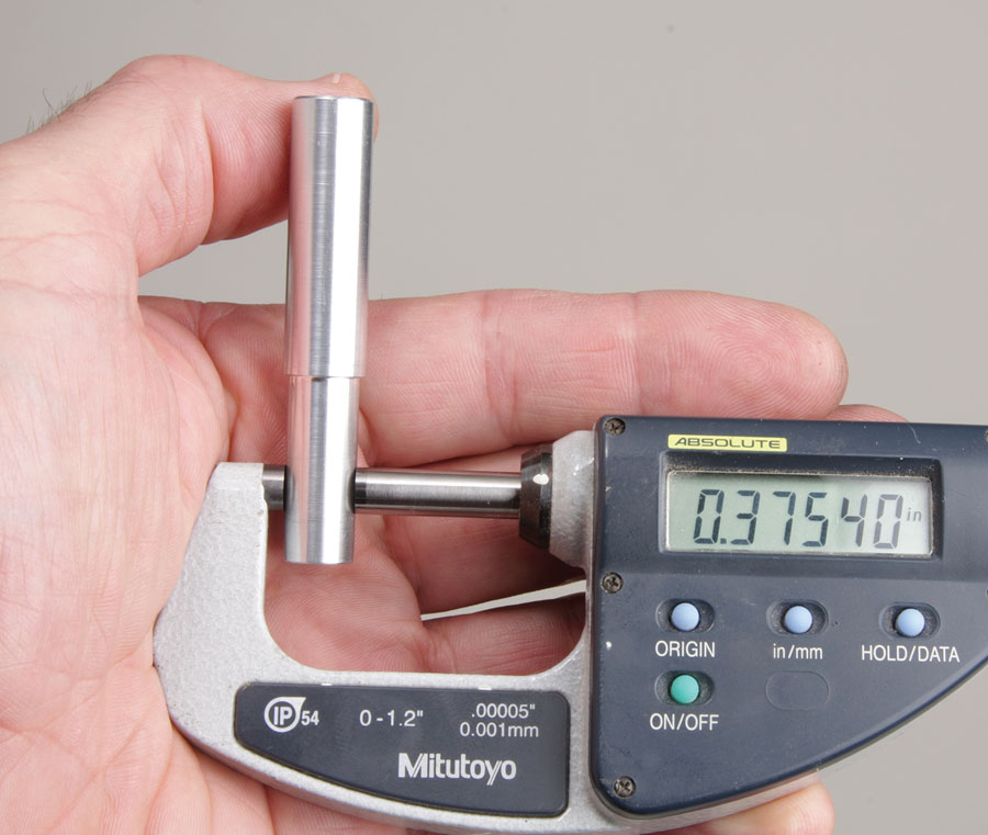
The second step measured 0.00075 inch larger than the first. A test with the hub revealed that one end would slip over the shoulder of the shaft, but the other end would not, an indication the drilled hole in the hub was slightly tapered.
Since the hub partially fit the middle step, a third step works for the press fit. It measured +0.0008 inch from the previous step.
While the method described is for fitting a shaft to an existing hole or hub, it can work the other way around, too, by step boring a hub to custom fit an existing shaft.
The basic ways to join an interference fit are by force, such as with an arbor or hydraulic press, a vise, or a hammer; or by using thermal expansion (heat) or contraction (cold). Parts that are joined by thermal process are referred to as having a “shrink-fit.” This is often the way propeller hubs are joined to crankshafts.
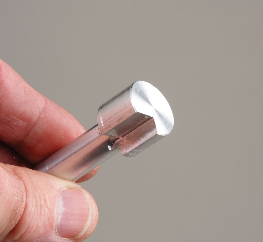
A final check confirms an interference and that the parts are ready to press together. The extended stem has a dual purpose: to gauge the hole for the correct interference fit and to align the parts for final pressing.
Heating is usually required on the tightest force fits. Steel has a coefficient of expansion of around 0.000006 inch, per inch, per degree Fahrenheit (F) and aluminum 0.000012 inch, per inch, per degree F. This tells us that when heated to 300 F, most hubs will expand sufficiently to allow even the tightest force fit to slip together easily. If you’re worried about overheating a sensitive part, lower the temperature a bit and put the mating shaft in a freezer. What’s important is the temperature differential. Heating the hub to 225F and chilling the shaft to 0 F (in a typical freezer) gives you the same fit as heating the hub to 300 F with the shaft at room temperature (77 F).
The American National Standards Institute (ANSI) has established definitions for four basic types of interference fits. They are light drive, medium drive, heavy drive, and force drive fits. The following is quoted from the ANSI guidelines:
- Light drive fits are those requiring light assembly pressures and produce more or less permanent assemblies. They are suitable for thin sections or long fits, or in cast-iron external members.
- Medium drive fits are suitable for ordinary steel parts or shrink fits on light sections. They are about the tightest fits that can be used with high-grade cast-iron external members.
- Heavy drive fits are suitable for heavier steel parts or for shrink fits in medium sections.
- Force drive fits are suitable for parts that can be highly stressed or for shrink fits where the heavy pressing forces required are impractical.
As the descriptions point out, the type of fit depends on the application. For connections that need to be permanent, use a medium, heavy, or force drive fit. A good example would be bearing races pressed into wheel hubs. These fits are “permanent” in the sense that they won’t come apart from normal use or abuse. Bearing races, of course, are designed to be pressed out and replaced, so exactly how permanent depends on many factors. A gear pressed onto a driveshaft can almost always be removed with a gear puller or by reversing the assembly forces. A rod or shaft pressed into a blind hole can usually be removed with a slide hammer or by applying heat to relax the grip. Parts that have been pressed together with a blind mechanical interlock can usually be released with heat. Nothing is really permanent if you’re determined enough, though the ultimate solution might prove destructive to one or both parts of the assembly.
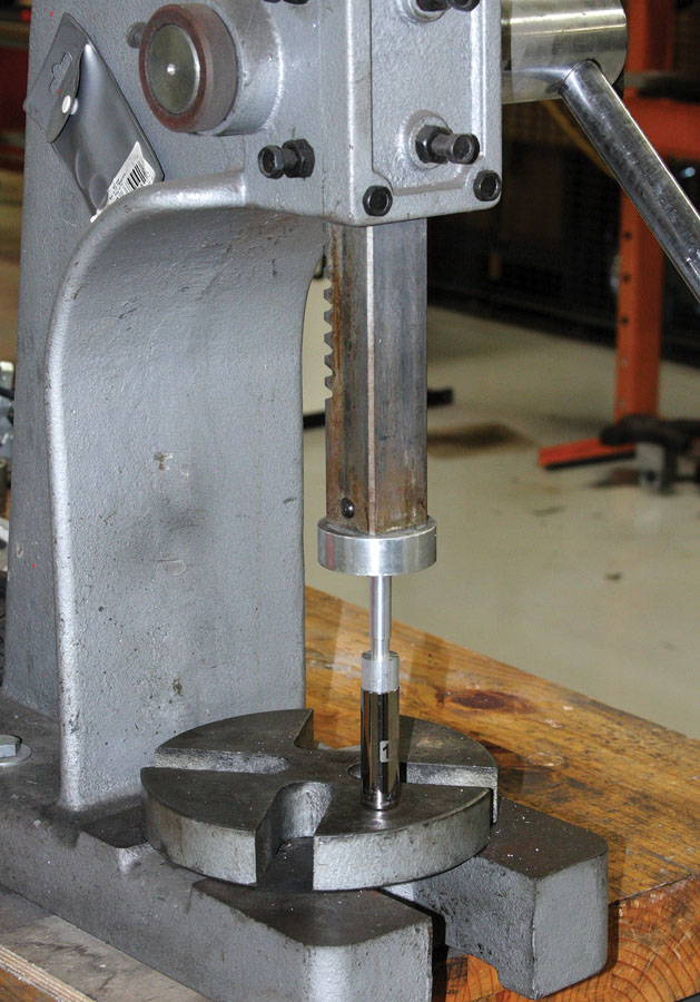
An arbor press is preferred for maintaining alignment when driving home interference-fit parts. But a well-placed blow with a soft-faced hammer will also do the trick. An appropriately sized socket is used to support the hub and provide clearance for the protruding stem.
There are a number of helpful websites with calculators for sizing parts, estimators for driving force, and holding power (the holding force is pretty much equal to force required for assembly).
Case assemblies often have alignment pins press fit into one or both halves to help alignment during assembly, but never both halves. Bolts or screws do the holding in these situations.
Section view of the pressed shaft and hub assembly after machining off the protruding stem. Note there is no noticeable delineation between the two parts.
Don’t mix materials if the assembly will be subject to temperature changes. The difference in the coefficient of expansion of an aluminum shaft in a steel hub could cause the press fit to come loose.

![]()
Bob Hadley is the R&D manager for a California-based consumer products company. He holds a Sport Pilot certificate and a Light-Sport Repairman certificate with inspection authorization for his Jabiru J250-SP.

