The way the aerodynamic lift on the wing of an airplane varies along its span has profound effects on both the plane’s aerodynamics and its structure. The spanwise distribution of lift force on the wing (the span load) affects the induced drag of the airplane and the loads on the structure of the wing.
Induced Drag
If we plot the lift as a function of the spanwise station on the wing, we get a curve that looks like Figure 1. The shape of this curve determines the span efficiency of the wing, and therefore the induced drag of the airplane. Induced drag, otherwise known as “drag due to lift” is drag that is created when a finite-span wing deflects the oncoming airstream downward to create lift. For a given amount of total lift, induced drag is minimized if the air is deflected the same amount everywhere along the span. This causes air to pass over the wing at a uniform, constant downwash angle.
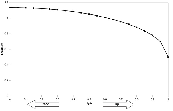
Figure 1: Typical Spanwise Lift Distribution.
Although a wing with this ideal uniform downwash deflects the same amount of air at every span station, lift still varies along the span. The reason is that some of the pressure difference between the upper and lower wing surface bleeds off around the tip. The result is decreasing lift as we move outboard on the wing, and it gives rise to the tip vortices that are shed downstream from the wingtips. These two phenomena, the uniform downwash combined with the finite tip losses, cause the spanwise lift distribution of an “ideal” wing to be elliptical.
As we have established, a wing of a given span, having an elliptical span loading, has the lowest possible induced drag for a planar wing of a given span carrying a given load. If the downwash is not uniform, the lift distribution will deviate from the ideal elliptical shape, increasing induced drag. Aerodynamicists use a “span efficiency factor (e)” to quantify this effect. The span efficiency of a wing is the induced drag of an ideal, elliptically loaded wing divided by the induced drag of the real wing at the same flight condition and wingspan. An elliptically loaded wing therefore has a span efficiency of 1.0.
A wing with a non-elliptical planform such as a constant-chord or straight-tapered wing can have a span efficiency approaching 1.0, if it is properly twisted to get an elliptical span load at the design point. The planform, if untwisted, would have a non-elliptic loading. The twist compensates and moves the span load toward the ideal elliptical shape. The twist can only drive the span loading to a true ellipse at one angle of attack, because the ideal twist is different for every flight condition. If the twist is properly chosen for the climb or cruise condition of the airplane, the wing can still be quite efficient. For most planforms typical of light airplanes, the washout needed to get good stall characteristics actually makes the span loading more elliptical, reducing induced drag.
Some builders make the foolish error of building their wings without the prescribed washout in an effort to make their airplanes faster. Ironically, in doing so, they not only hurt the stall characteristics of their airplanes, they usually get no drag decrease at all, and may actually increase the drag of their airplanes at cruise.
Typical span efficiencies for complete airplanes range from about 0.75 to 0.85. This is significantly lower than the span efficiency that can be achieved with a properly twisted wing with a tapered planform. The fuselage and the wing-to-fuselage junction affect the span load and hurt span efficiency, and this is particularly true on low-wing airplanes, which are prone to premature flow separation at the wingroot if the junction with the fuselage is poorly sealed or has no fillet.
Wing Structural Loads
The design limit load factors of airplanes vary depending on their mission, but no light airplane is designed to less than a 3.5 G limit load factor. This means that each wing must be able to carry a load equal to at least 1.75 times the weight of the airplane. The lift pulls up on the entire length of the wing. On a cantilevered wing, all of this lift is reacted at the root by the weight of the airplane acting down on the fuselage. Because the centroid of the lift is well outboard on the wing, the lift produces a large bending moment that tries to fold the wing upward at the root. It is the function of the wingspars and other structures to resist this bending moment, so that the wing carries the weight and stays attached to the airplane, even when the airplane is pulling G up to the design load.
The magnitude of the wingroot bending moment is determined by three factors: the weight of the airplane, the number of G it is designed to withstand, and the distance between the wingroot attach point and the centroid of the lift on the wing. The larger any of these quantities become, the larger the wingroot bending moment becomes. The position of the centroid of lift is set by the planform and twist of the wing. The most important variable is the span, but once the span has been set, the wingroot bending moment is determined by the shape of the span loading curve. This is one area where tapering the wing can have a dramatic effect because of how taper affects the span load.
If every section of the wing were deflecting air through the same angle (constant downwash), the span loading would be elliptical, as we have already explained. If every section of the wing were flying at the same lift coefficient, then the span load would look like the planform of the wing. On a truly elliptical wing, both of these conditions are met. On a non-elliptical wing, the span load ends up somewhere between the elliptical (constant-downwash) loading and the planform-shaped (constant lift coefficient) loading.
A reasonable engineering approximation (called the Schrenk Approximation, after its inventor) to the span loading of an untwisted wing is that it is exactly halfway between the elliptic loading and the constant-lift coefficient loading. Schrenk’s Approximation, when adjusted properly for twist, provides a good enough estimate of the span loading of unswept wings for preliminary structural design, and it is simple enough to program quickly in a spreadsheet. The details can be found in NACA Technical Memorandum 948 (1940).
Figure 2 compares the span load (calculated using Schrenk’s Approximation) of a constant-chord wing and a tapered wing carrying the same load. The important thing to note is that the tapered wing is carrying more load near the root and less load near the tip. This means that the centroid of the lift on the tapered wing is inboard of that of the constant-chord wing. The lift is acting on the root through a shorter lever arm, so the wingroot bending moment is lower.
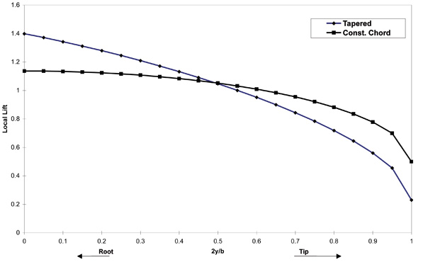
Figure 2: Effect of Taper on Lift Distribution.
For a given total lift, the constant-chord wing will exert more bending moment on the wingroot than the tapered wing because the lift load is centered further outboard. The spar must be stronger, and therefore heavier in order to resist this increased bending moment.
The weight disadvantage of a constant-chord wing is increased by the fact that the root chord of a constant-chord wing will be less than the root chord of a tapered wing of the same area and aspect ratio. The root chord of the constant-chord wing is smaller, so the spar will be thinner because the thickness of the wing is a constant percentage of the chord. To carry the same bending moment, a thinner spar must have thicker caps and will therefore be heavier.
For airplanes of moderate gross weight and aspect ratio, the weight penalty of a constant-chord wing is small enough that this planform is a reasonable choice where ease and cost of manufacture are major considerations.
Optimizing
For a fixed wingspan, a wing with an elliptical span load has the lowest induced drag. If we look at wings of constant weight, however, the picture changes. Adjusting the span loading so that the centroid of lift is slightly farther inboard than that of an elliptical distribution will reduce the wing bending moment, making the wing lighter. If we then increase wingspan to match the original wingroot bending moment, we end up with a wing that has a slightly lower span efficiency but a slightly larger wingspan.
Induced drag drops proportionally to span squared and increases linearly with span efficiency, so it is possible to sacrifice a little span efficiency to increase span and come out ahead. At constant weight, the optimal wing will have a span load that is somewhat root-loaded compared to an elliptical distribution, and a slightly larger span.

![]()
Barnaby Wainfan is a principal aerodynamics engineer for Northrop Grumman’s Advanced Design organization. A private pilot with single engine and glider ratings, Barnaby has been involved in the design of unconventional airplanes including canards, joined wings, flying wings and some too strange to fall into any known category.


