Almost all modern avionics systems for ether certified or Experimental aircraft use mil-spec D-sub connectors with gold plated contacts. With rare exceptions, most systems use just three types of contacts. High-density pins are typically used on IFR navigators and audio panels. Standard density sockets and pins are used on most other devices. If you are staring at a smaller number of pins in the connector—typically nine, 15, 25 or 37—those are standard density.
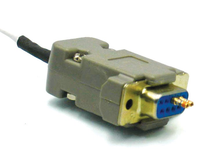
Spare pins inserted into a DB-9 socket are the start of troubleshooting potential wiring issues and far more elegant than a length of safety wire.
When it comes time to troubleshoot your system and wring out some wires, you will need to find a good way to make contact between the multimeter test leads and connector contacts. One method is to insert some spare pins of the opposite gender into the connector pins you want to probe, and touch the test leads to these “pin extensions.” This works well, but you still have to carefully hold the multimeter probes onto those pins, which can be difficult in many aircraft locations. Here are some better solutions that keep you from wishing you had three hands or smaller fingers.
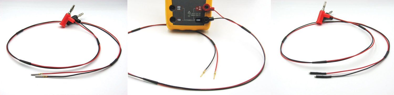
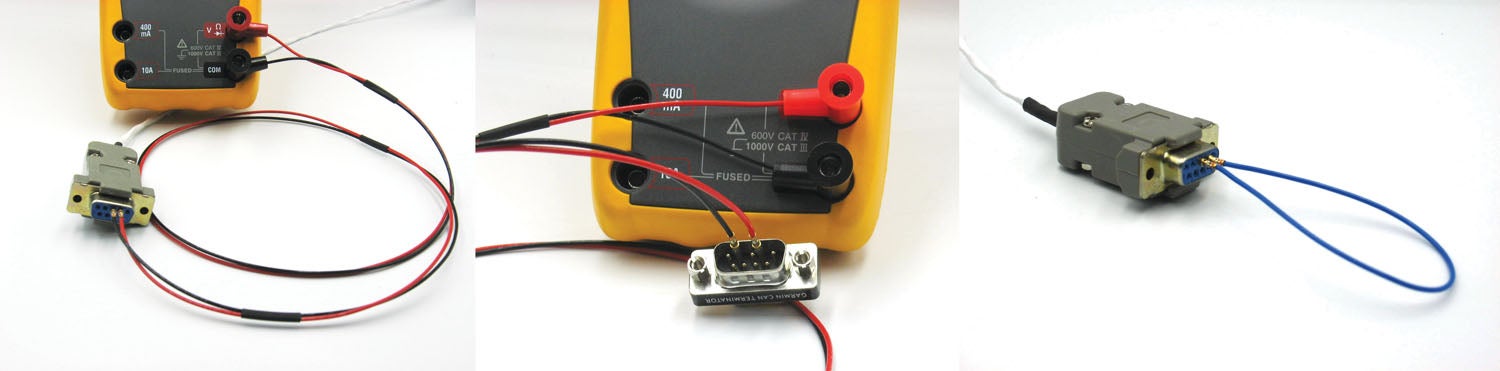
A better approach is to use some of your extra high-quality pins, wire and readily available banana plugs to make test leads for probing male connector pins (left). This is a test lead set for probing female connector pins (center). It is also a good idea to put heat shrink over the test lead pins so they can’t short together when testing two adjacent connector pins (right). This also strain relieves the pins and makes the test leads last longer.Here’s an example of probing female pins in a connector (left). Note also that most avionics connectors in your aircraft have at least one pin connected to a ground wire, so if you want to check for shorting of any signal wire to ground, just plug the black lead into a ground pin, and probe any of the signal pins with the red wire with the meter in the ohm or continuity check (beep) position. If you want to check for voltage on any connector pin, again just plug your black wire into a ground pin, then use the red wire with the meter in the voltage position to probe the pins that should have power applied. Here’s an example of probing male pins in a connector (center). You can also use these pins to make jumper cables (of either gender) when you are using the test leads at one connector to verify the continuity of a pair of wires at another connector in the aircraft (right).
As Martha and Wendell Solesbee near completion on their Lancair Evo, they encounter the minor setbacks that make the “90% done, 90% to go” expression ring true.
Rapid strides are being made in the development of ultralight electric motorgliders. Dean Sigler talks to a few of the manufacturers at the forefront of this field.