It was a perfect fall day in Ohio. The sun was out, the air was crisp with a light breeze, and I was helping my dad do some work on his Van’s RV-8 project that he had recently moved out to the hangar. My dad, who looks like Geppetto from Walt Disney’s Pinocchio, with his silvery white hair, black shop apron, and reading glasses worn low on his nose, was inside the hangar leaning over the side of the fuselage and struggling to put a fastener into one of the cockpit floorboards. Despite having the hangar door open, the problem was that the sides of the fuselage were blocking a lot of light from getting inside the cockpit area, and my dad couldn’t clearly see when the parts lined up. As many of you reading this probably already know, old age and low lighting makes seeing details difficult. The need for reading glasses is an unfortunate part of getting older, but young or old, we shouldn’t have to put up with poor hangar lighting.
Who among us thinks there is too much light in their hangar? How many times have you tried to use a flashlight, droplight, or shop light to illuminate that part you are working on, only to find that you can’t find a good spot to put it, it won’t aim at the right spot, your body blocks the light, or a whole slew of other issues?
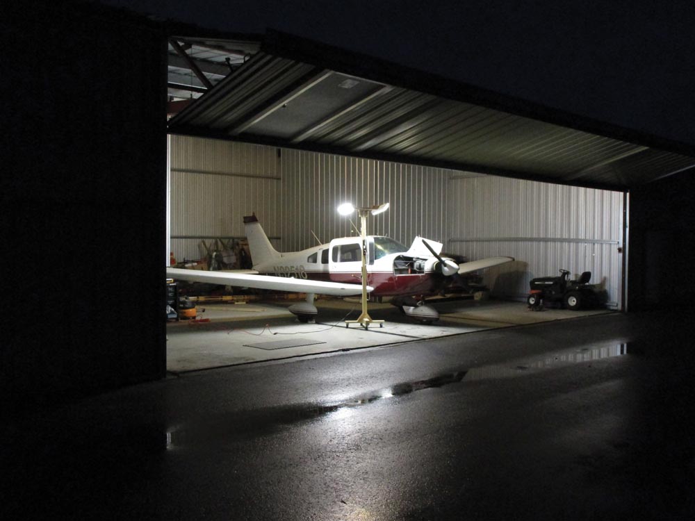
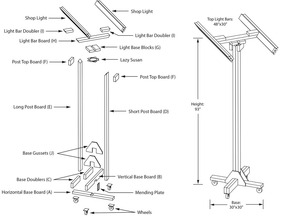
Lack of decent lighting in hangars is what drove me to make this light tower. Like any good design, I thought out a list of criteria I wanted to incorporate. They included: low cost, easy to build, simple construction, no special tools, small footprint, stable, plenty of light, the ability to adjust the light, and a place to hang cords and hoses. The good news is, I was able to meet my requirements. And even if you are not a woodworking expert, there is nothing about this project that requires special fabrication skills. The power tools I used were a miter saw, a table saw, a jigsaw, a cordless drill, and an impact driver. However, a couple of hand saws and a drill are all that’s required. If you have basic woodworking skills and tools, you can make your own mobile shop light tower.
Materials
I have included below a bill of materials of the items I used to construct this mobile shop light. I found them at Lowe’s and Harbor Freight because that was convenient for me, but you should be able to find comparable products at any hardware store.
Step 1: Begin by cutting the 2×4 boards to size. The chart describes the lengths and number required. I’ve also included how to cut each 2×4 to get the most out of each board with the least amount of scrap. For the -inch plywood base gussets (J), just begin by cutting to the size listed, and later I will describe how to cut them to shape. Grain direction of the plywood is not really important, but I chose horizontal because I like the way it looks. Remember, a 2×4 is really 3×1 inches, so the only column you need to pay attention to is the length. Also note that most saw blades will remove 1/8 inch of material due to the width of the blade, so make sure you cut on the correct side of the line. Striving to be as precise as possible will serve you well with any project, but on this project, if you are off slightly, it really won’t matter.
Cutting the Base
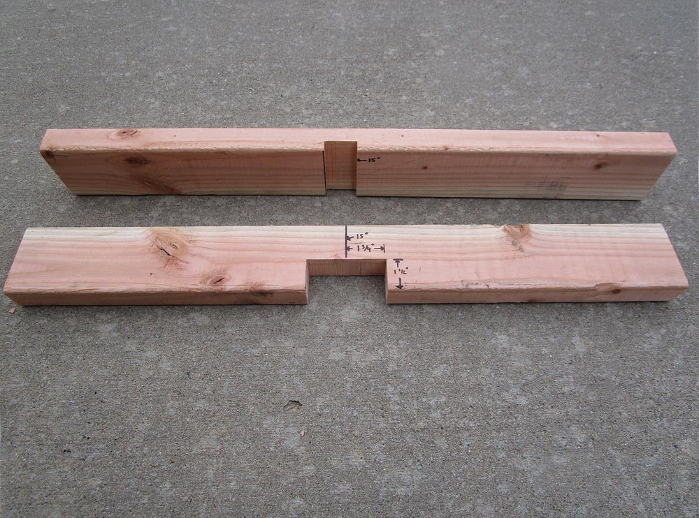
The two most complicated pieces make up the base of the light tower. When finished, one part lays flat horizontally, and the other part will intersect in the middle vertically so they make a “+” sign, with a groove that is used to lock in the long board of the light post. In order for this to work, you’ll need to remove some wood.
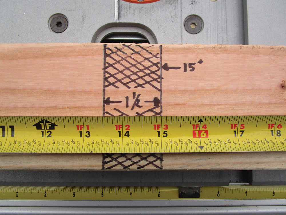
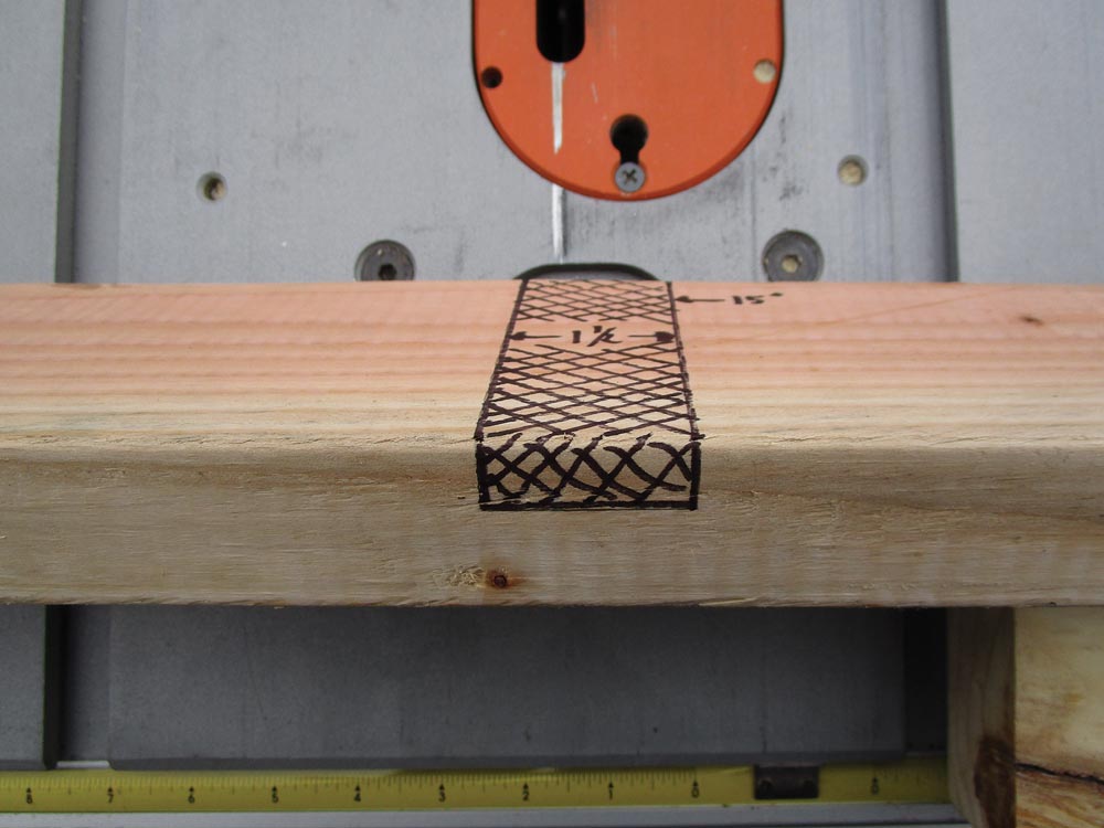
Step 2: Starting with the horizontal base board (A), measure 15 inches from one end to find the center, and draw a line across the face of the part. From that centerline, measure over 1 inch and draw another line across the face of the part. The area between these two lines is going to be removed using the table saw with the blade raised inch above the table. Extend the lines onto one edge of the part, and place the part line side down on the table saw. With the table saw off, hold the part tight against the table saw miter gauge, and line the saw blade up to the centerline marks you made on the edge so that the blade will cut between the lines. While still holding the part against the miter gauge, slide it away from the blade, start the table saw, and make the cut. Then bring the part back to the start point, slide it over about 1/8 inch, and repeat until the saw blade is touching the line for the 1-inch mark, and stop. If done correctly, you should have a groove 1 inch wide and inch deep across the face of the part.
Step 3: On the vertical base board (B), there is a notch cut out of one edge of the part so that it will fit over (A). Once again, measure 15 inches to the center, and draw a line across the face of the board. Next, measure 1 inch to both sides of the centerline, and draw lines across the board. Using the two lines you just drew from one edge, measure down 1 inch from each, and draw a line to connect these two marks with a line. You’re drawing a 1×3-inch rectangle, with one side on the edge of the board. Using the same technique as before, place the board on edge, and use the table saw to remove this rectangle. You may want to do this in multiple passes by first setting the bade to inch, then 1 inch, and then 1 inch. You can also use the drill-and-jigsaw technique described later on for cutting the gussets.
Cutting the Post and Light Bar
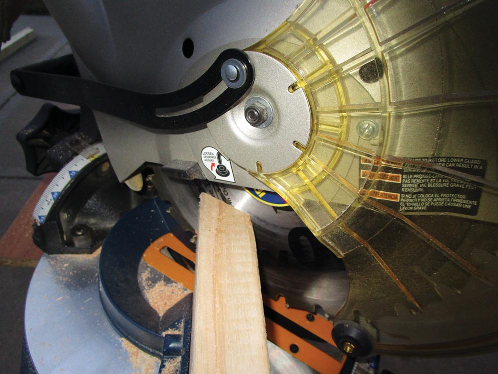
Step 4: Take both the long post board (D) and short post board (E) and place one end on edge on the miter saw, set the blade angle to 45 degrees, and cut.
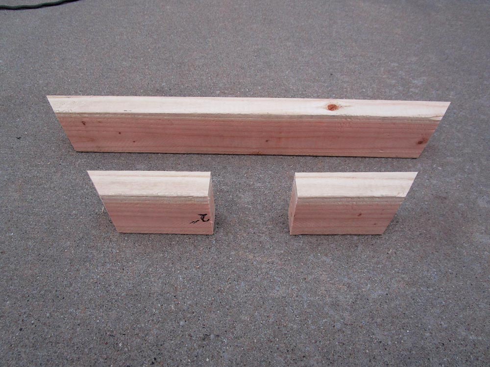
Step 5: Take both the light bar board (H) and light bar doubler (I) and place one end on edge on the miter saw, set the blade angle to 32.5 degrees (mine has a notch there), and cut. Pay attention here! Cut the other ends to 32.5 degrees, ensuring that the angles are aiming to a center point that would make a triangle, or when looking at the board on edge, one side is 24 inches long or 12 inches long, and the other side is shorter. On the light bar doubler (I), along the 12-inch length, find the center and cut in half so that you will have two 6-inch blocks that will each have an angle on one end.
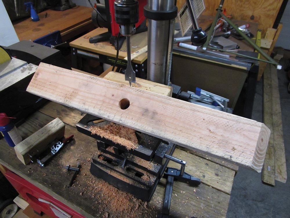
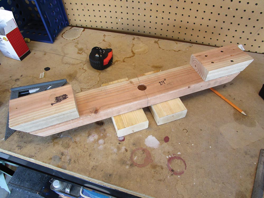
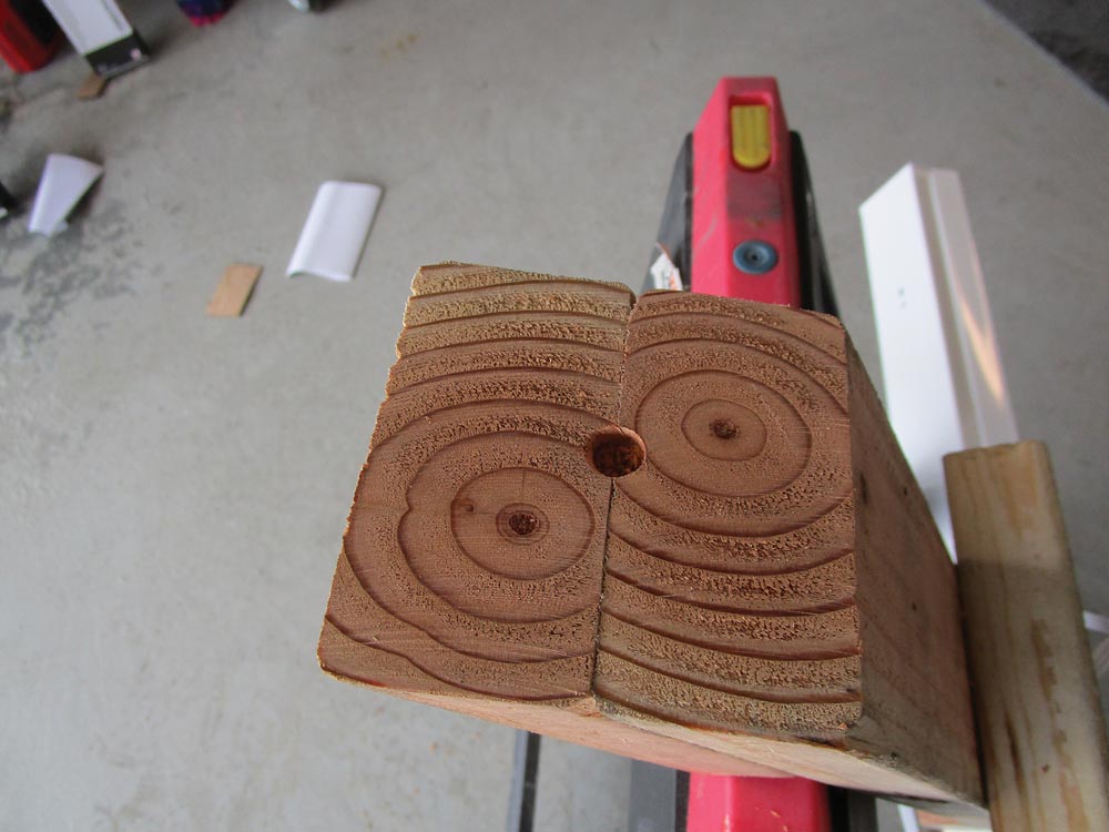
Step 6: On light bar board (H), with the 24-inch side face up, find the center both up and down, left and right, and drill a 1-inch hole with a spade bit.
Step 6: Drilling a 1-inch hole in Part H. Although Part H is tilted in this photo, the hole is drilled perpendicular to the face of Part H.
Cutting the Gussets
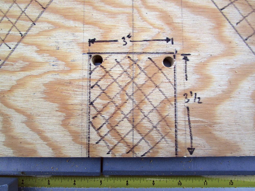
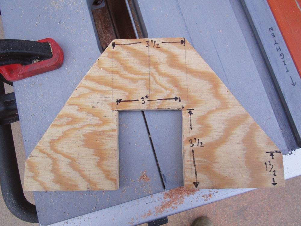
Step 7: The base gussets (J) are 12 inches wide by 8 inches high. Starting at the 12-inch wide base, mark a centerline 8 inches high. Along the bottom, from the centerline, measure over 1 inch on each side, and draw a line vertically the height of the gusset.
Step 7: Marking the gussets on plywood. Note that the 11/2-inch centerline offset lines should extend to the top of the gusset, making the top dimension 3 inches, not 31/2 inches.
From the base corners, measure up 1 inch on each side and draw a short line. Next, draw a diagonal line from the short line up to the nearest 1-inch line from the centerline at the top. Repeat for the other side.
From the bottom of both 1-inch centerline offset lines, measure up 3 inches and draw a line to connect these marks. Remove this area using a jigsaw and by drilling a 3/8-inch hole at each inside corner of this rectangle. These holes will allow you to reposition the jigsaw to make the corner cuts. Use the jigsaw to cut off the triangles off each side as well. Final adjustments can be made with a file.
Assemble the Base
Step 8: Now that all the parts are cut, we can begin to assemble the mobile shop light tower, starting with the base.
Hold base board (B) so that the notch is toward the ground, and with base board (A) groove side up, place a scrap of 2×4 vertically in the groove. The scrap 2×4 will be replaced later by the long post board (D).
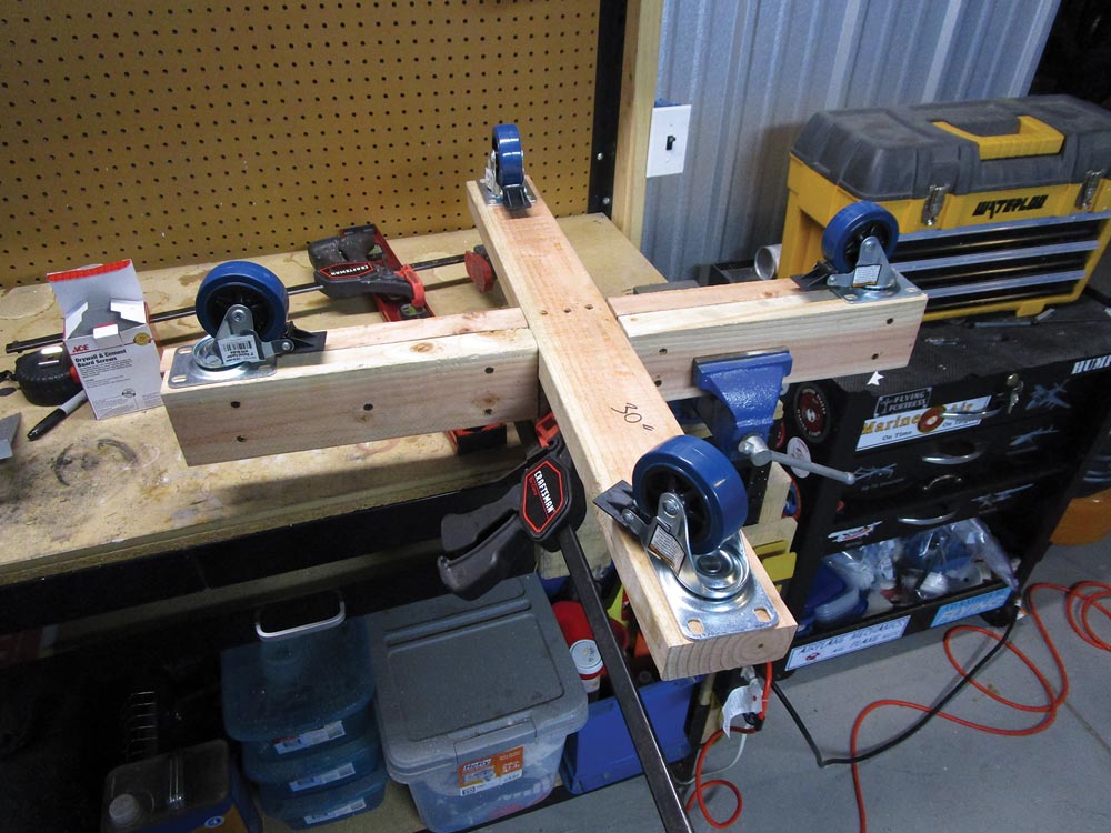
Slide the notch of (B) onto (A) so that the notch rests on the non-grooved (opposite side of the centerline) half of (A) and against the scrap piece of 2×4. A C-clamp works well here. Holding this assembly together, flip it over, place (B) in a vise, and run three evenly spaced 3-inch #9 drywall screws from the bottom side of (A) into (B).
Step 8: Assembling Parts A and B to form the base. Note the scrap 2×4 clamped in place where Part D will eventually be located.
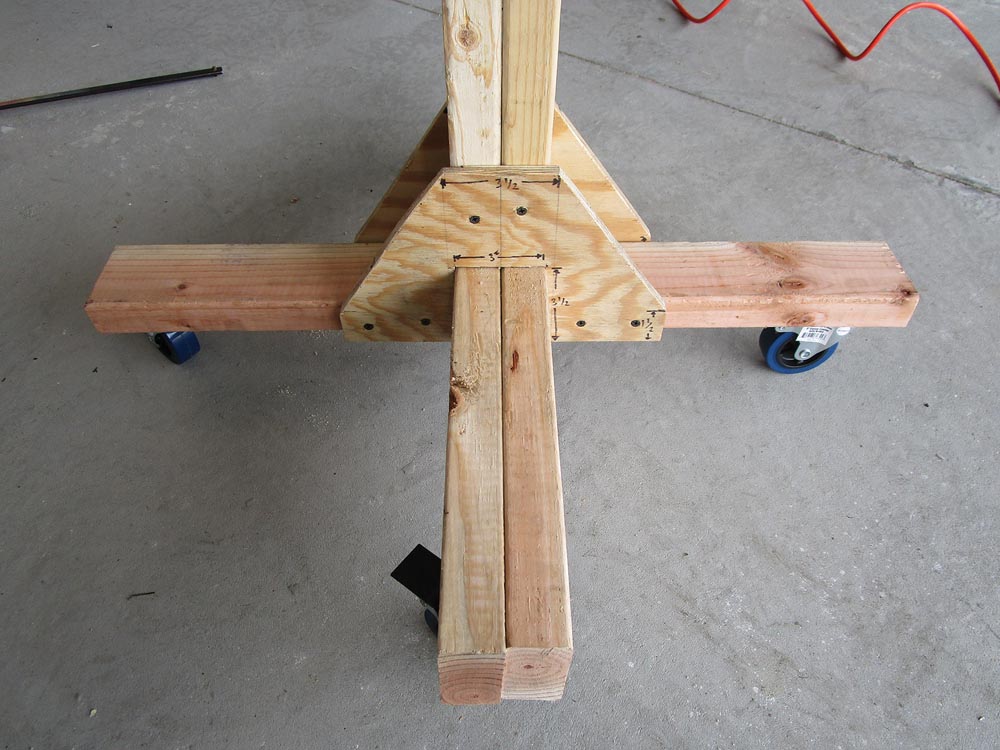
Step 9: With the scrap 2×4 still in the groove, butt the base doublers (C) against it, and secure to (B) with 3-inch #9 drywall screws on each side so you end up with a 3×31/2-inch leg.
Step 10: Place one 3-inch caster wheel onto each leg, and use four 1-inch #8 lath screws in the inside corners of the wheel frame slots to secure them in place. Remove the scrap 2×4, flip the assembly over, and check to see if all four wheels rest on the ground. Don’t worry yet if there is a slight wobble, or if all four wheels are not touching the ground. We will fix this later.
Adding the Post
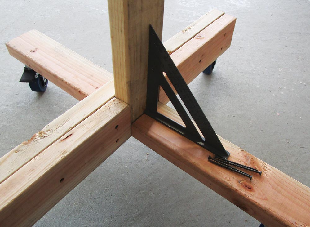
Step 11: With the base assembly oriented so that the wheels are on the ground, place the flat end of the long post board (D) into the groove so that the 45-degree cut at the top is facing toward (B). Check that it is square, and drive four 3-inch #9 drywalls screws from (D) into (B).
Step 12: Place the flat edge of short post board (E) on top of the edge of (B), ensuring that the 45-degree cut at the top faces toward (D) and forms a “V.” Then align (E) to (D), and drive two 3-inch #9 drywall screws at five evenly spaced intervals along the post.
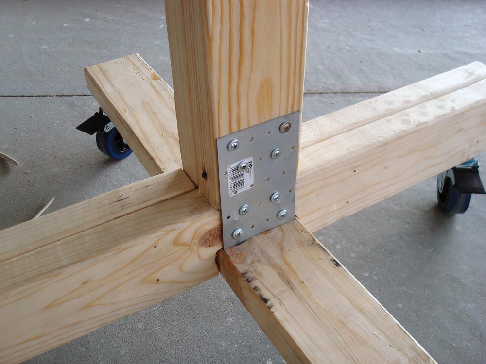
Step 13: At the base where (E) meets (B), secure the 31/8×5-inch mending plate with eight 1-inch #8 lath screws. Warning! Use a clamp to hold the mending plate because the screws are likely to grab and turn the plate into a sharp, rotating blade.
Adding the Gussets
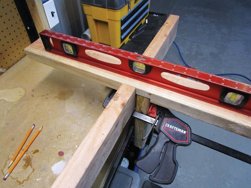
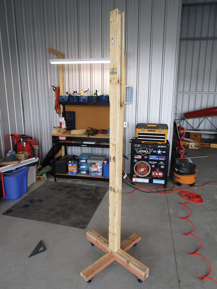
Step 14: After this next step, there should not be any wobble left in the base and post. Place the plywood base gussets (J) over (B) and against the edges of (A) and the post. Secure the gussets to only one side of (A) with two 3-inch #9 drywall screws. Now ensure that all four wheels are in contact with the ground. You may have to push or pull the post to put enough weight on the wheels to get all four to touch. With all four wheels on the ground, secure the gussets to the other side of (A) with two screws each. Finally, take two 3-inch #9 drywall screws on each side, and secure the gussets to the post. There should no longer be any wobble.
Preparing the Top
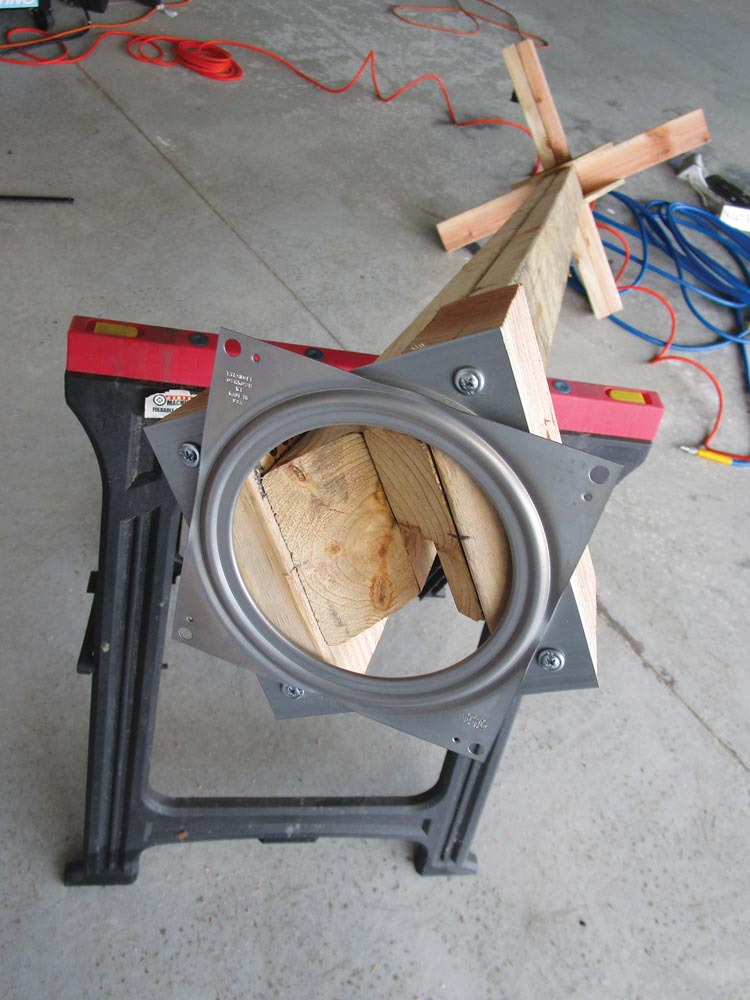
I found for the next few steps that leaning the post over a sawhorse was easier than standing on a ladder.
Step 15: From the top side of (A) on both sides, measure up the side of the post, and draw a line across the 2×4 at 80 inches. Then at the very top, measure 1 inch and put a mark on the inside of the 45-degree angle. Measure 3 inches on the post top block (F), and make a mark that is visible on the edge. Align the center marks of (F) with the center marks of the post while also aligning (F) to the line you made at 80 inches, and secure with four 3-inch #9 drywall screws on each side.
Step 16: Observe the lazy Susan; one side should have holes near the edge, and the other side’s holes will be more inboard. Place the side with the inboard screws against (F), and the edges should line right up. Then secure with four 1-inch #8 lath screws.
Building the Light Bar
Step 17: Before we can hang the lights, we need to build something to hang them from. Start with the light bar board (H), and place it with the 24-inch side down against the bench. Use a square to draw lines tangent to the hole in the center on both sides of the hole. On the light base block (G), measure 3 inches to find the centerline, mark the edge, and align it to the lines you just made on (H) so that the center mark touches the side of the hole, and secure each side of (G) to (H) with three 3-inch #9 drywall screws each.
Step 18: Flip the assembly over, and place one light bar doubler (I) at each end of (H) so that the edges and angles are both aligned. Pre-drill four holes in (I) to prevent splitting, and use four 3-inch #9 drywall screws to secure in place. Be careful that the screws do not protrude through the angled side.
Step 19: Flip the assembly so you are looking squarely at the face of the angle, and locate the center of the angled face by drawing a line from opposite corners so they form an “X.” Using a 3/8-inch drill bit, drill a hole about 1/8-inch deep at the center of the “X” to provide a recess for a screw that is part of the light.
Easy Electrical Work
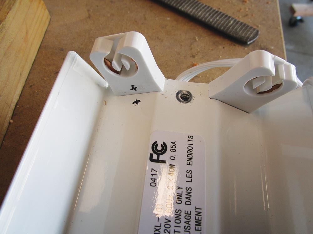
Step 20: Switching gears to the lighting, don’t be intimidated by the electrical work; it’s really pretty simple. With the shop light unplugged, place it on the workbench so that where the fluorescent bulbs will go is facing up. In order to make it easier to put it back together, choose where one bulb will be, and make a small mark at each end with a black marker near the bottom of the bulb sockets and on the metal panel as well. Remove the three screws that hold the metal panel to the base, remove the panel, and pop the bulb sockets off.
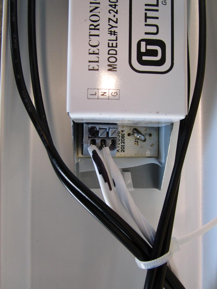
Step 21: Follow the wires that are part of the power cord to where they connect to the ballast and, using a black marker, make a mark on one wire and also on the ballast were the wire goes. With a screwdriver, press down on the small button on the ballast that holds the wires in place, and gently pull the wires out.
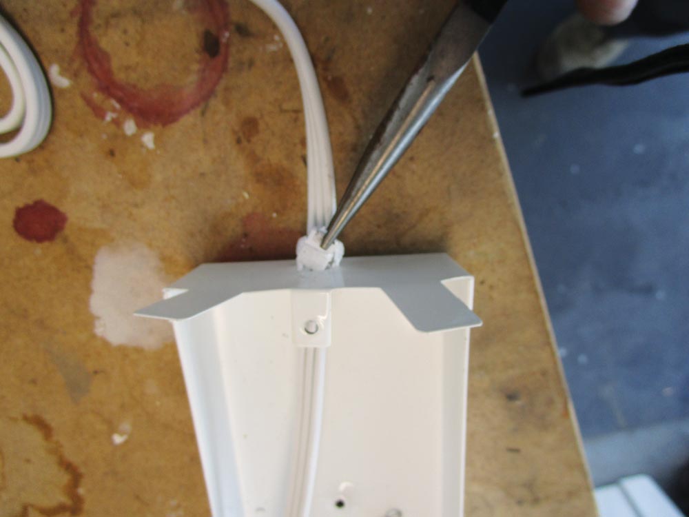
Step 22: Unscrew the ground wire, then using a pair of needle-nose pliers, remove the plastic plug that holds the cord in place in the base and remove the cord. It’s a bit of a pain to remove the plug, but it can be done. Be careful not to bend the metal tab on the base.
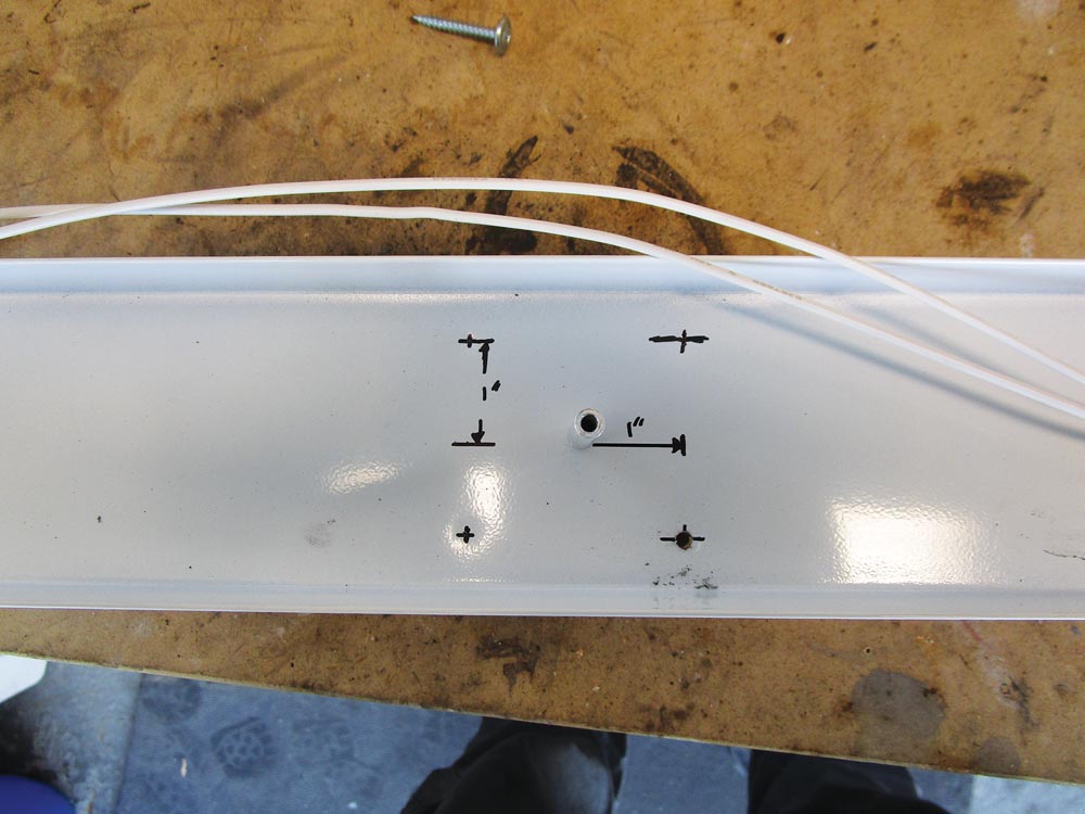
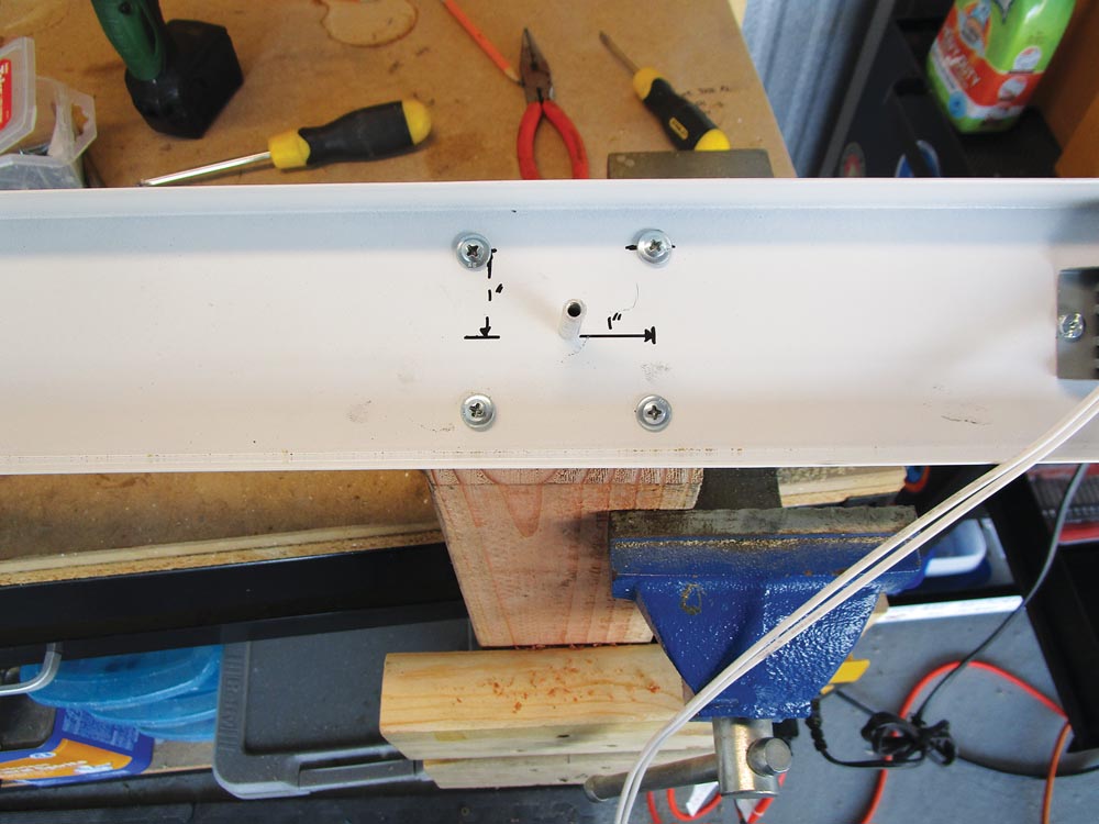
Step 23: On the base of the light fixture, where the middle screw was located, there should be an aluminum bushing, which is the center of the light. This is where we need to locate some holes to drill. From the center screw hole, measure up 1 inch and over 1 inch and make a mark. Repeat this process three more times until you, in essence, have drawn a 2×2-inch square that is centered on the hole. With a block of wood to back up the base of the light, use a drill with a 5/32-inch drill bit to drill holes at the four corners of the square and then deburr the holes.
Step 24: Place the light bar assembly vertically in a vise so that one of the angled faces is up and facing you. Place the base of the light on the angle so that the center screw on the shop light base is inside the 3/8-inch hole you previously drilled. Center the shop light base to the light bar assembly, and secure it with four 1-inch #8 lath screws.
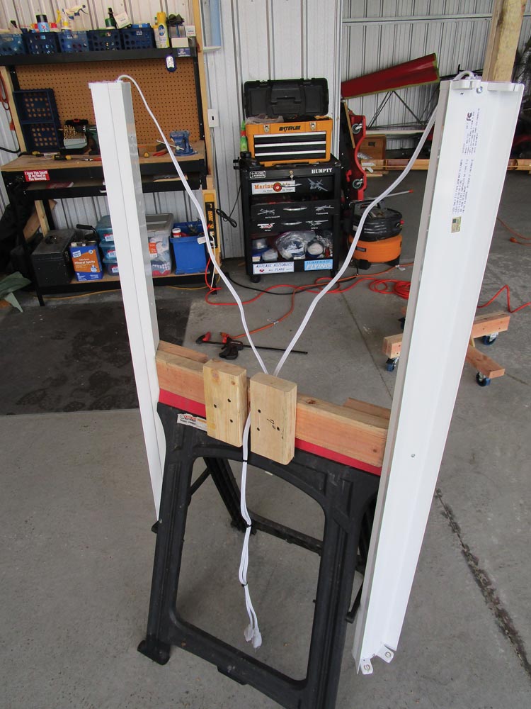
Step 25: Take the power cord and insert it through the 1-inch hole in the light bar board (H) so that it goes in between the light base block (G) boards and out the top, and then into the shop light base the same way it came out. Make sure the wires can reach the ballast, and put the plastic plug back in place.
Step 26: Reattach the ground wire with a screw, and using the marks you made before, align the wires with their respective holes in the ballast, press on the button, and insert the wires. Give the wires a light tug to make sure they are attached, then take the panel and slip the light sockets back into place.
Step 27: Making sure the sockets you made the marks on are in the correct location, place the panel on the shop light base. Be sure the wires are tucked inside, then fasten the panel with the three screws. Repeat this process for the other light.
Adding the Top
Step 28: This next part will be easiest with the help of a ladder. Take the completed light bar assembly, route the plugs for the light through the lazy Susan and out one side of the V, and place the assembly on top of the lazy Susan.
Center the assembly on the lazy Susan, rotate it until the holes appear, and secure it with four 1-inch #8 lath screws.
Step 29: Add four fluorescent light bulbs, and that completes the main assembly of the mobile shop light tower.
Finishing Touches
Much like a kit aircraft, I have given you step-by-step instructions to build the mobile shop light tower, but the final finishing touches are left to the builder. I will tell you what I did, but you should do what fits your needs.
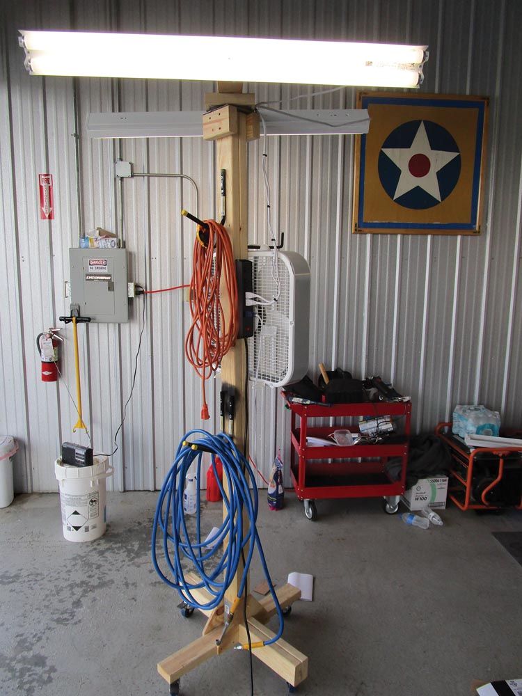
Step 30: I chose to mount a six-plug power supply to the post on the same side I routed the plugs for the lights. I plugged the lights into the top two sockets of the power supply, left a little slack in the light wires, and secured it in place with two 1-inch #8 lath screws. I use the breaker switch to turn the lights on or off. This also provides a nice portable source of electric outlets anywhere in the hangar so that you don’t have to run long extension cords all over the hangar.
Step 31: Speaking of extension cords, I have a couple in the hangar, as well as an air hose for the compressor. Adding hooks to the post makes a great place to store these. I also wanted to hang a box fan at chest height so when working in the hangar during the summer, I can keep more than just my ankles cool.
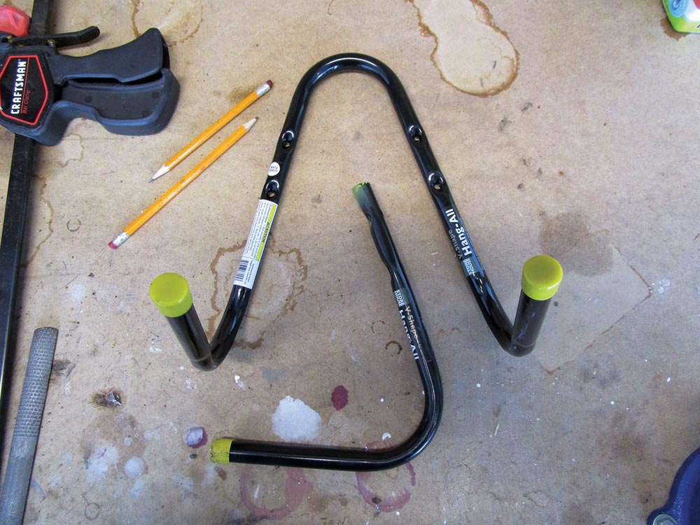
I found that the Harbor Freight V-shaped metal hangers are dirt cheap but won’t fit as is. The solution is to measure up an inch from the screw hole nearest the bend, and cut it with a hacksaw or cutoff wheel. Do this for both sides of the bend, discard the bend, and file any burrs off the ends of the two hooks. I sprayed the ends of mine with some black spray paint I had laying around so that they wouldn’t rust. I placed the hooks where I wanted them and used 1-inch #8 lath screws to secure them.
Making It Better
Since I know some of you will want to make this better, here are a few ideas. If you have an uneven floor like dirt or gravel, I would make the legs (A and B) longer and use bigger wheels.
My first thought was to hang halogen work lights from the light bar, but this was quickly abandoned; once I considered the amount of heat they produce, I pictured them melting a canopy. I chose fluorescent lights because they are cheap, electricity is included in my rent, and I don’t use them every day, so they will last a long time.
Another option is upgrading to LED lights. They are not much more expensive, and prices continue to come down. I have heard they are brighter, use less energy, are available in different styles, and last forever. One problem I have read about is that LEDs are directional, meaning the light doesn’t emit 360 degrees; it’s more like 300 degrees because of how the LED strip is placed. This may or may not be an issue. If you live in an area with a cold climate, LEDs do not need to warm up like fluorescent bulbs.
Another idea is to design a removable center section so you can adjust the height to fit in a garage or make it easier to transport. The number of modifications are really only limited to your imagination.
This is a simple weekend project that anyone can build. Once you build one, you will wonder how you ever did without it, and everyone at the airport who sees it will want one too.
Bill of Materials
| Part Description | Product | Qty. | Each | Cost |
|---|---|---|---|---|
| 8′ Pine 2×4 | 8′ Pine (Select) 2×4 | 4 | $3.27 | $13.08 |
| Pine Plywood 2’x2’x.5″ | Pine Plywood 2’x2’x.5″ | 1 | $5.50 | $5.50 |
| Shop Light | UtiliTech 4′ Shop Light | 2 | $12.98 | $25.96 |
| Fluorescent Light Bulbs (2-pack) | GE 40X Work Spaces 2-pack | 2 | $11.86 | $23.72 |
| 6-Plug Power Strip | Utilitech 6-Outlet Metal Power Strip | 1 | $12.97 | $12.97 |
| Mending Plate | Miltek 3.125″x5″ | 1 | $0.88 | $0.88 |
| 6″ Lazy Susan | Lazy Susan 6″ | 1 | $6.97 | $6.97 |
| Box of Lath Screws | Buildex Teks #8×1″ Lath Screw (box) | 1 | $6.47 | $6.47 |
| Box of Drywall Screws | Grip Rite #9×3″ | 1 | $6.47 | $6.47 |
| 3″ Rubber Caster Wheels | HF #61855 | 4 | $3.99 | $15.96 |
| V Shaped Metal Hanger | HF #68995 | 1+ | $1.99 | $1.99 |
| Total | $106.89 | |||
Material Cut List
| Part | Description | Length | Width | Height | Material | Qty. |
|---|---|---|---|---|---|---|
| A | Horizontal Base Board | 30 | 3.5 | 1.5 | Pine 2X4 | 1 |
| B | Vertical Base Board | 30 | 3.5 | 1.5 | Pine 2X4 | 1 |
| C | Base Doublers | 13.25 | 3.5 | 1.5 | Pine 2X4 | 2 |
| D | Long Post Board | 84 | 3.5 | 1.5 | Pine 2X4 | 1 |
| E | Short Post Board | 81.5 | 3.5 | 1.5 | Pine 2X4 | 1 |
| F | Post Top Block | 6 | 3.5 | 1.5 | Pine 2X4 | 2 |
| G | Light Base Block | 7 | 3.5 | 1.5 | Pine 2X4 | 2 |
| H | Light Bar Board | 24 | 3.5 | 1.5 | Pine 2X4 | 1 |
| I | Light Bar Doubler | 12 | 3.5 | 1.5 | Pine 2X4 | 1 |
| J | Base Gussets | 12 | 8 | 0.5 | Pine Plywood 2’x2’x.5″ | 2 |
2X4 Cutting Scheme
- Long Post Board (D) & Light Bar Doubler (I)
- Short Post Board (E) & Light Base Block (G) (2x)
- Horizontal Base Board (A);Vertical Base Board (B); Light Bar Board (H)
- Base Doublers (C )(2x) & Post Top Block (F)(2x)

