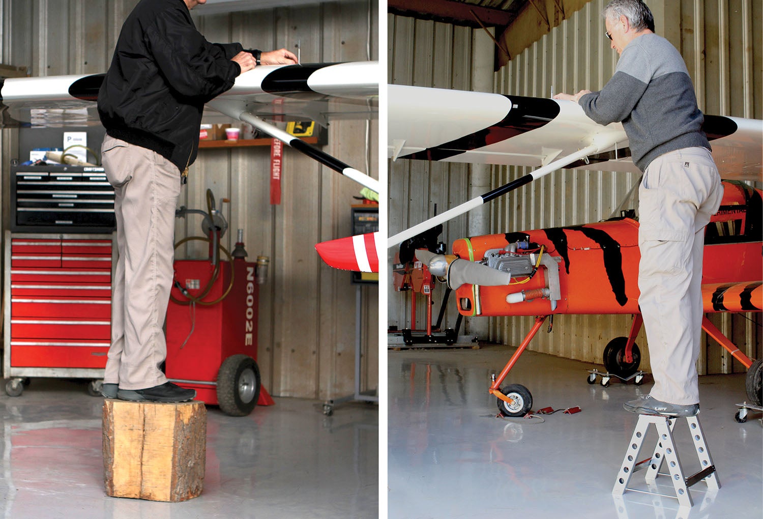
I affectionately refer to my Jabiru light-sport as being a “low high-wing” airplane. This is because, despite it being a high-wing configuration, you have to stoop pretty low to walk under the wings. On the plus side, I don’t need a full-size ladder to get above the wing to visually check the fuel level. I do need a boost, and for the longest time it’s been via a section of a liquidambar tree trunk. Although it happens to work fine in the hangar, it is too heavy (24 pounds) to take with me. While it hasn’t happened yet, I would be in a bind if I needed to check the tanks or refuel at a remote airport with no ladder.
The commercial stepladders and stepstools I looked at were either taller than I needed or looked too cheap. It didn’t take long before I started to envision what a homebuilt stepladder might look like: very simple, about a foot tall and a mere 2 pounds.
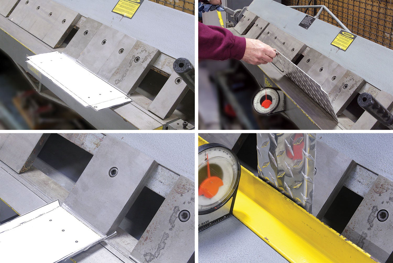
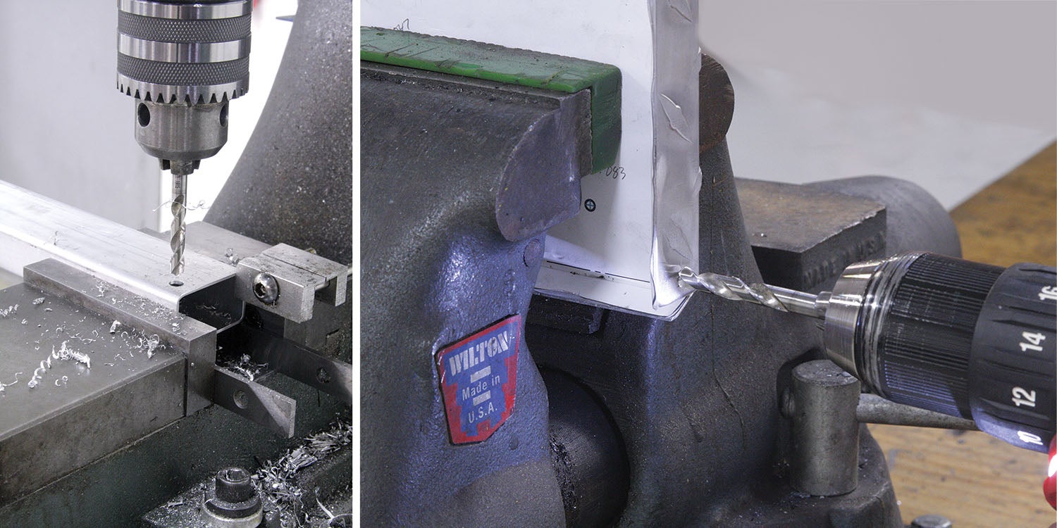
The tools and construction techniques for the project included lathe work for the bolts and pins, mill work with the indexer for the aluminum pivot bolts and nuts, basic tap and die threading, sawing, some drilling, sheet-metal bending with a pan and box brake and TIG welding.
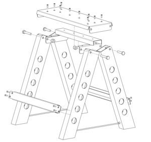
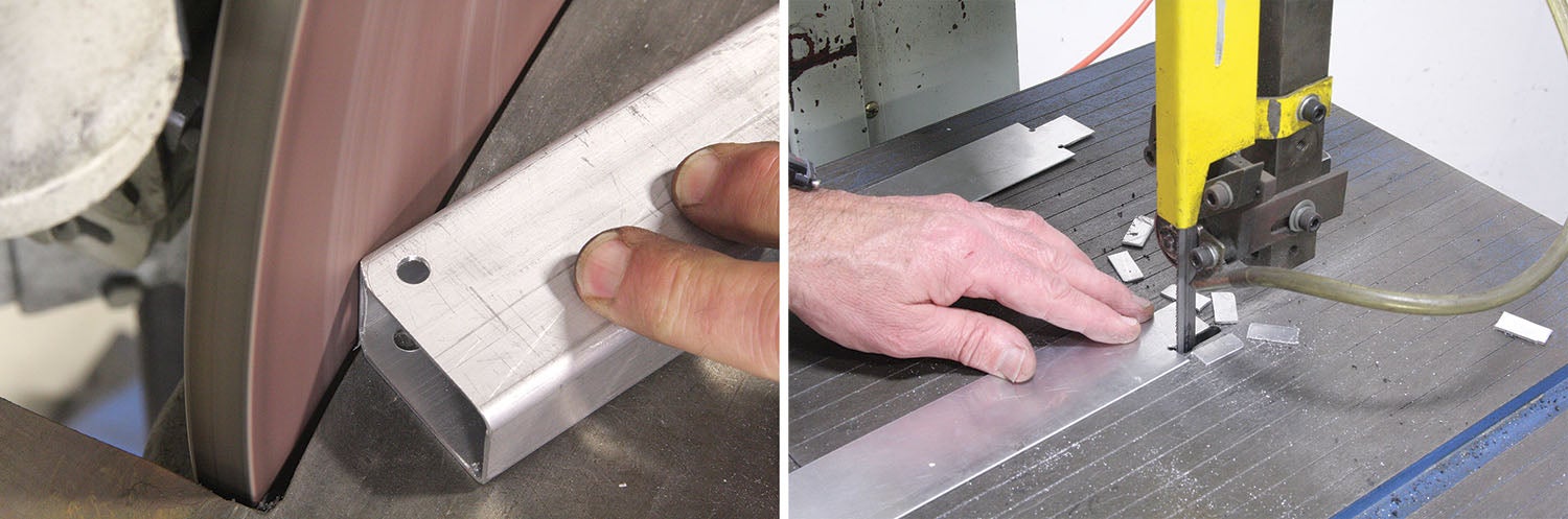
Like many of my “not going to the moon” projects, I designed my stepladder based on material I had sitting around the shop. I happened to have some 1×1.8×0.062-inch rectangular 6061 aluminum tubing that was originally extruded for a mountain bike frame. I used this material for the legs. Since no one is likely to come across this particular tubing, I changed the drawing to make the legs using standard 1x2x0.062-inch 6061 aluminum rectangular tubing.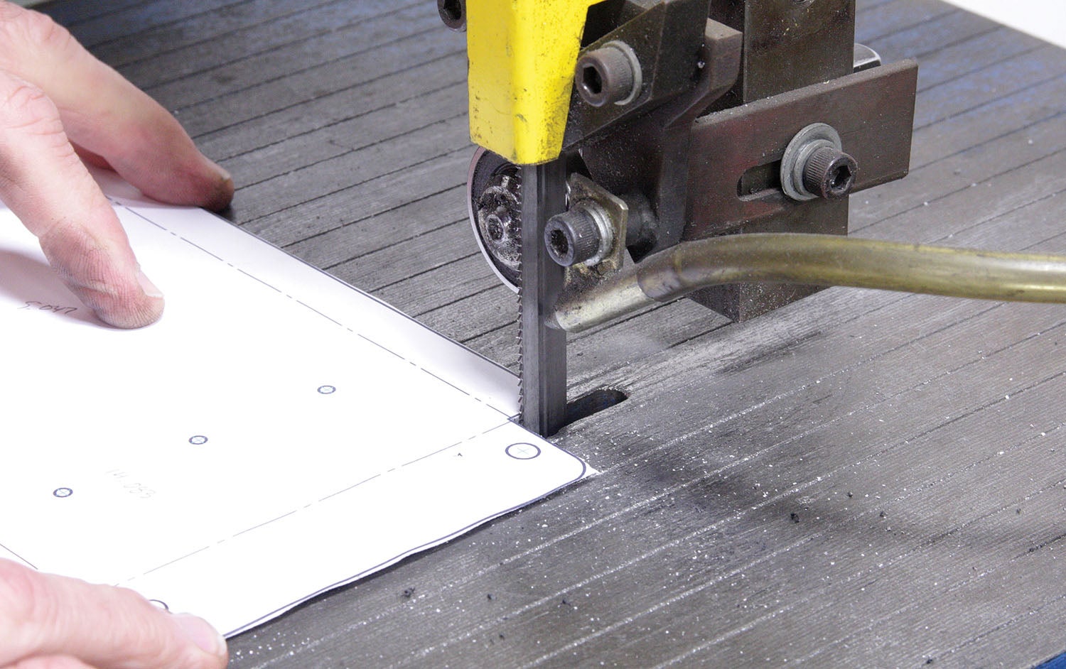
The top was made from 12x24x0.073-inch aluminum diamond tread sheet from Home Depot. Like the leg material, this was a leftover from another project and not purchased specifically for this stepladder.
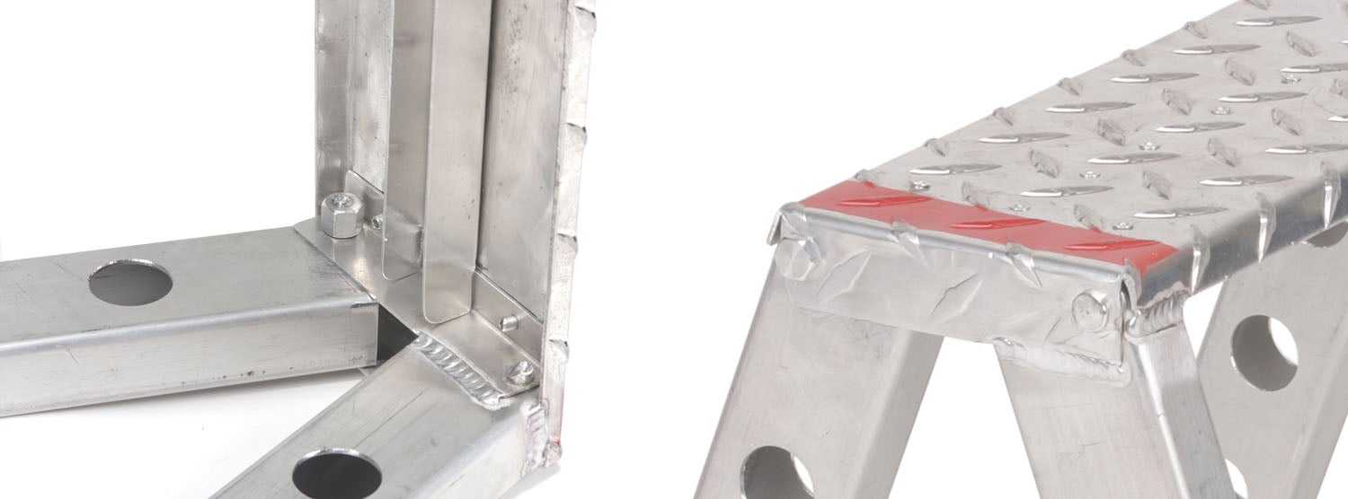
The stretcher braces and reinforcing channel for the top were made from 0.040-inch 6061 aluminum sheet. The pivot bolts, nuts and alignment pins were made from 6061 aluminum bar stock.
The rivets for the leg angle brackets (six rivets) and channel brace (four rivets) are 1/8-inch aluminum flush pop rivets with a 0.25-inch grip length. The rivets for the long stretchers that connect the legs in pairs are standard 1/8-inch steel pop rivets (eight rivets) with a 0.25-inch grip length. They are the only steel parts on the ladder.
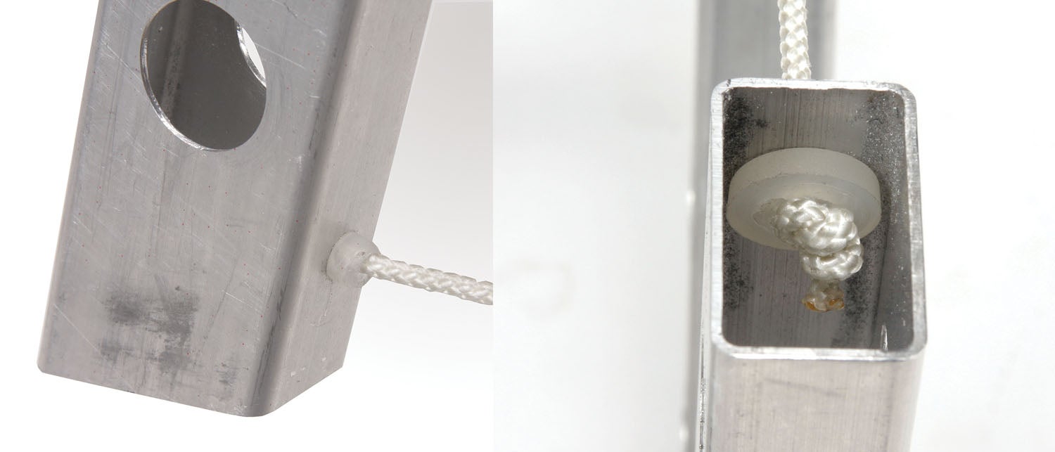
To save weight, instead of traditional scissoring braces for the pivot mechanism, 1/8-inch nylon ropes were tied off at the correct length and sleeved with a nylon bushing in the aluminum legs.
You will note from the photos that one set of legs are TIG welded to the top. I considered using screws and/or rivets to fix the non-pivoting legs to the top, but welding seemed to be the best option. Of course, you need to be able to weld or know a good welder…my ladder is welded because I happen to know Billy Griggs, an ace welder with tons of experience welding lightweight aluminum structures (Billy builds custom bike frames and was the source of the leg material).
I originally did not include the channel brace to reinforce the top. It was added after initial use caused the top to sag under my 180 pounds. Adding the brace increased the strength to where a 220-pound person can stand on it with no noticeable deflection.
Download the detailed design drawings for the machined parts as well as flat patterns (with bend lines) for all the sheet metal parts. That’s it for now. Time to get back in the hangar and use my new stepladder to check my fuel level!


