 Now that we had the pieces and parts for the tail section and wings done as well as the tail cone assembled and mated to the fuselage, it was time to move forward—literally. The next area for us to concentrate our efforts on is the boot cowl, which is the metal skin between the firewall and the backside of the instrument panel. The fitting of the boot cowl is a bit tricky because the firewall placement has to be established, which affects the boot cowl placement. You also have the instrument panel frame to attach to the aft side of the boot cowl skins. These are three big, vital areas, none of which are currently attached to the growing airframe.
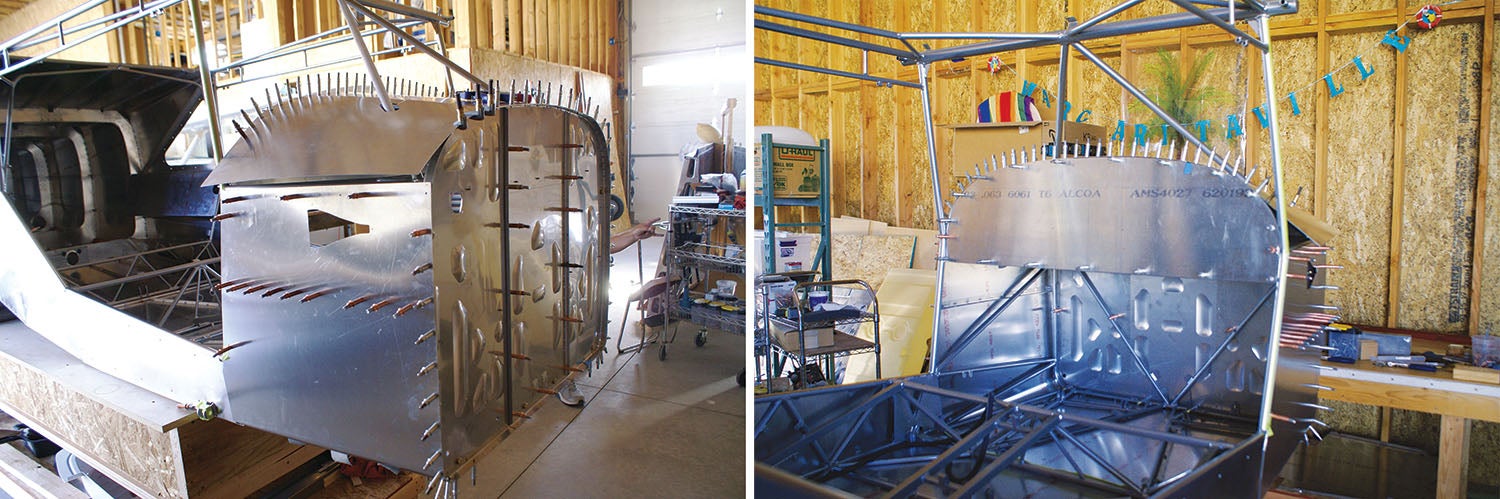
At first, when I saw the skins for the boot cowl, I was amazed that there were so few pre-drilled holes in the pieces. But after doing the fitting, I understand why. When a steel cage is welded, it moves around slightly due to the heat from welding, which causes it to not be dimensionally stable. I would venture a guess that no two steel fuselage cages would ever be “exactly” the same. The skin pieces are precision made, so putting them onto a welded steel cage just wouldn’t work with too many predrilled holes, thus there is a lot of transfer drilling to do with the boot cowl skins.
More Helping Hands
To begin this process, we had the help of Dean, another neighbor who is also a builder, working with Mike to locate the firewall by centering it on the forward part of the fuselage cage. What followed should be familiar if you’ve been reading this series—clamping it in place, drilling and Clecoing the firewall. This gave us a stationary point to build back from. With the frame for the instrument panel Clecoed in place, we could fit the various pieces of the boot cowl. Getting the multiple spacer strips and cowling attach straps that fit around the edge of the firewall cut to size so they fit just right was a bit of a pain, sort of a wrestling match, but we got them fitted and Mike seemed to do a great job. In the end, things seemed to come together very nicely.
There were also several iterations necessary with the fitting due to getting the instrument panel frame straight and flat so all fit up nicely. Mike had to cut a notch in one of the skins to get the fit right with the steel cage, but that is just part of the process. When it comes to cutting a skin, I get very nervous watching and just have to trust that all will come out OK and it did! All in all, with the tweaking that had to be done and having it all Clecoed together, it seems to be nicely fitted.
The key to this part of the build is that you don’t rivet the boot cowl yet—you’re only fitting it—because there is a lot of work to be done inside and you’ll need to have access. So it came apart again! We carefully labeled the location of each of the boot cowl pieces and various spacers around the firewall as we removed them because each piece is specifically drilled and cut to size for an exact location, then these fine pieces were set aside to be riveted in place another day.
Like a House
This is the point of the build that I tend to liken to building a house. You have the foundation and framing go up, followed by walls and a roof. This part goes pretty fast and you can see that you are actually going to have a house some day, but then come the nasty details that slow things down—electricity, plumbing, insulating, drywall, cabinets and all the other amenities. All have to be completed before you can live in it. You know what I’m talking about.
My dear neighbor, Paul, has repeated to me several times, “Now you know what the homebuilders mean when they say 90% done and 90% to go.” Those words are haunting me to this day! Now that we have the frame of the airplane, it feels like we have come so far. But at this point of the build it is on to so many details of what has to happen to make this little bird into a flying machine. Lots of work!
Travel With a Purpose
We bought a prop from Western Aircraft Propeller Service and that gave us a great excuse to take a trip to Oregon to pick it up. Then we decided to extend our trip to include a flight to Ketchikan, Alaska, to visit our daughter, then pick up the prop on the way home. A break from building is needed once in a while to maintain sanity. We had a wonderful week to regenerate the building juices.
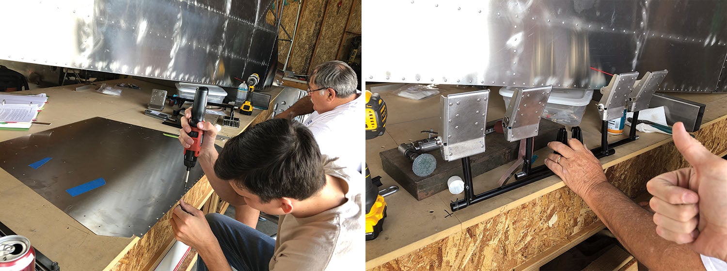
Back to the build. After putting the front floor panel in, we had to build the rudder pedals, which really seemed strange to me. I would have thought that they were one piece that you just attach where needed. Nope! They needed to be assembled. We had some assistance from our son, Jed, who was very fortunate in that I let him do the riveting! The pedals connect up to the rudder tubes, which had to be custom fit to length to allow freedom of movement and installed to the pre-located nut plates under the floor panel.
We had another day of reorganizing in which we reached a milestone in our build. The big box full of the larger airplane parts was empty. What a huge accomplishment! We tore it down and had a bit more floor space in the hangar.
Building Toward Control
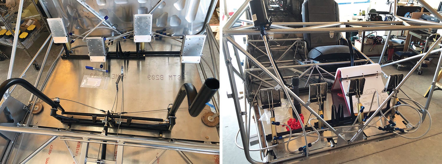
There are many miscellaneous systems that come into play that need to be accounted for at this point of the build. We focused on getting the control sticks in place with the pulleys and cabling for the rudder and ailerons, inserting the elevator pushrod, installing the hydraulic brake cylinders to the rudder pedals and getting them attached to the frame, building the seats and getting them adjusted with the stops in the correct location. I have been assigned to Quality Control (QC) and assisting with miscellaneous tasks, making sure all is attached correctly according to the manuals. As an example, Mike installed the brake lines, then gave me the manual page showing how they should be installed and asked me to double-check his work. Then he walked away. I have also been diligently logging the work being done.
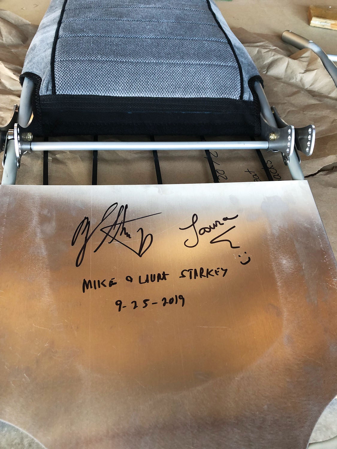
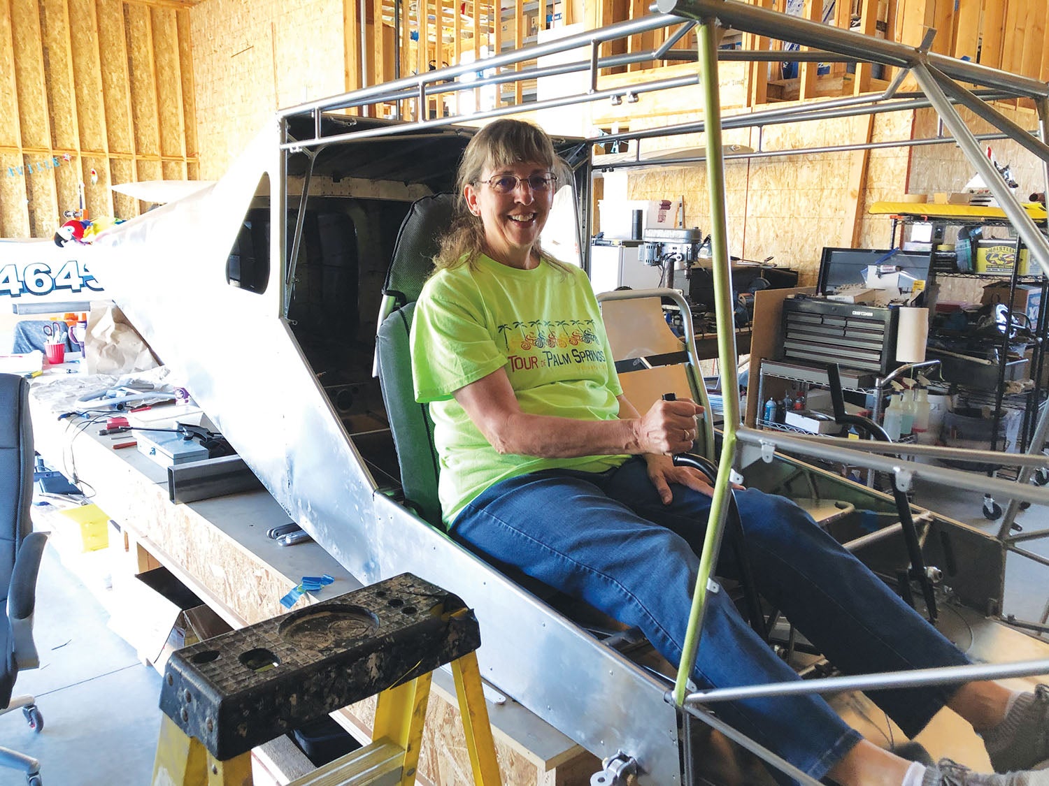
The stick grips (Tosten Model CS-8) would have to wait for another day due to the fact that we have picked out grips that not only have radio buttons but trim and autopilot controls as well, which will need to be wired with the rest of the panel. Plus, we need to have the height of the stick adjusted to our comfort level. It all has to magically come together so we still fit in the interior with good stick movement. To test our choices, we had to get in and make airplane noises! (Mike insisted on having the left seat, of course.) We also had a bit of fun signing our names to the bottom of one of the seats. Kind of a neat token that commemorates the build for us!
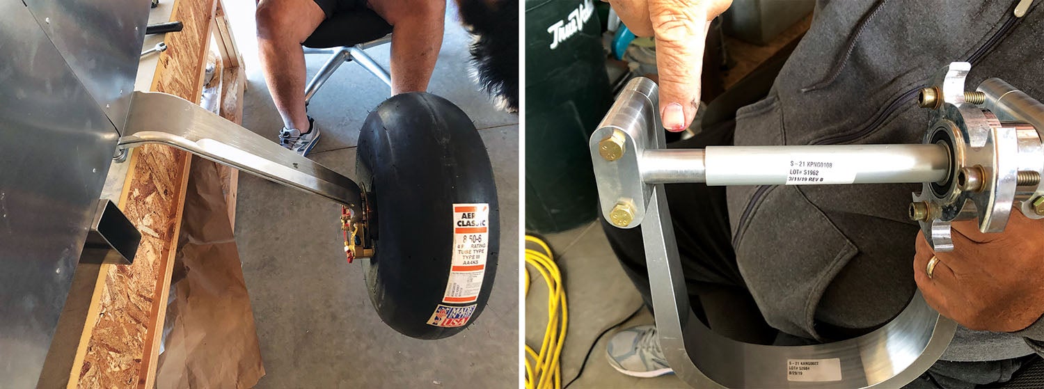
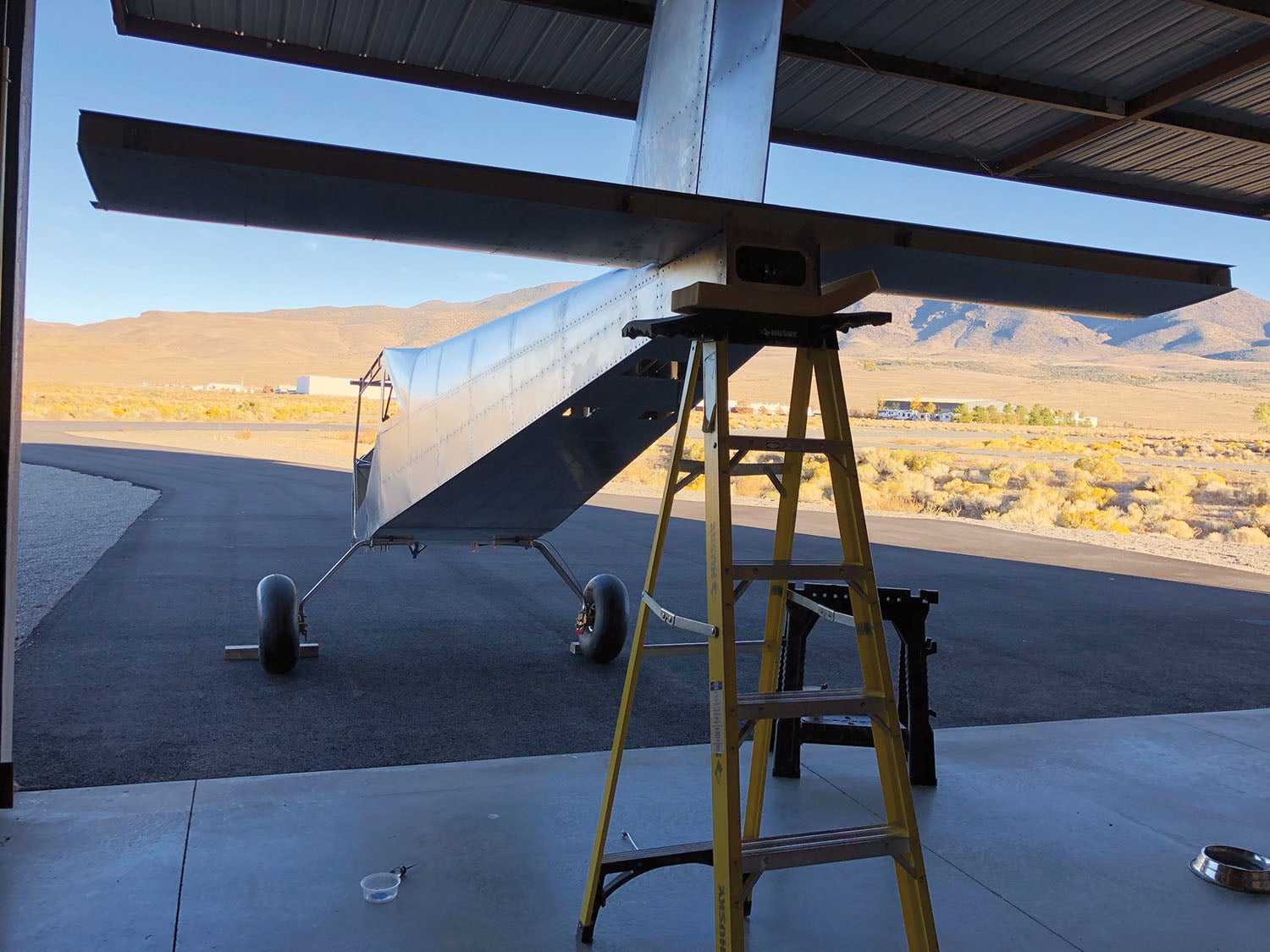
With those tasks complete, it was finally time for us to get this baby on the ground and off the table. We decided to go with the oversized “tundra” tires, probably more for the cool factor than anything, but this will give us the option to do some backcountry flying to Idaho or landing on dry lakebeds, if desired. With main gear legs attached, it was time to get the dual-caliper brakes installed—we decided to go with these for safety and strong braking ability.
There are so many pieces that I was never aware of before. The S-21 kit comes with standard braking (a single-caliper system) whereas the dual-caliper system literally doubles the braking capacity, something needed due to the larger diameter tires; they have a much longer “arm” working against the brake disk. The caliper mounting plates for the dual system did not have any holes drilled into them for mounting on the end of the main gear, so holes had to be drilled into these mounting plates. Mike (logically, I thought) used the standard caliper mounting plate that was provided with the kit as a template to drill the holes for the dual-caliper mounting plate.
Once drilled, he attached the brake calipers and held it up to the gear to find out that the clocking for the dual calipers is different than the standard, thus the holes were drilled in the wrong place! Ugh! Easy mistake to make, so beware if you get dual brakes—drill holes in the proper place! He was able to get the clocking correct on the other one and get one set of brakes mounted correctly. There will be mistakes along the way; you just have to roll with the punches, order the replacement piece and move on to other work, which there is always plenty of.
Trike It Is
We long ago agreed to making our plane with tricycle gear rather than as a taildragger mostly (OK, totally) due to my preference. I know that the taildragger looks cool, but I have very limited experience with a taildragger. I really don’t like how squirrelly it is on landing so, frankly, I want the control on landing as a priority rather than the cool factor.
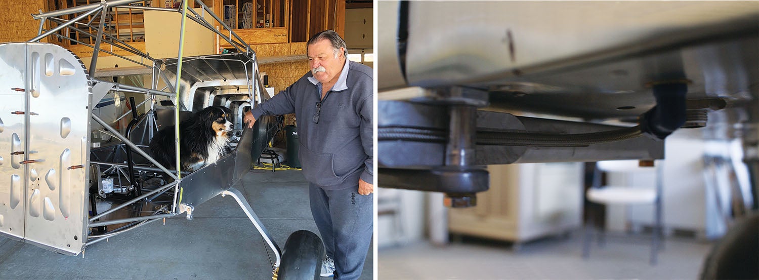
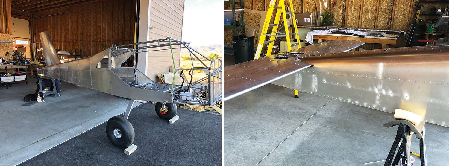
The nose fork for the tundra tires is a special-order item to accommodate the width of the tire. The fork is big and beefy and looks pretty awesome with the oversized tire. The nose gear assembly for the trike went smoothly. About four days later, we received the new mounting plate for the dual-caliper brakes in the mail and completed the main gear brakes with tires. With the help of a couple of friends, we lifted the S-21 off the table and put her on the gear. What an awesome moment! Now we can wheel her around and the tables are a thing of the past for the plane.
Mike is always great at checking out other people’s planes and picking up ideas that can be used to accommodate our needs more effectively. Our friend, John Pratt, who has a RANS S-20 Raven in Minden, Nevada, provided the inspiration for handy modifications to our build. First, we incorporated into our build two plywood pieces to act as mounting surfaces—one for the battery, com radio and ELT mounted behind the passenger seat, and the other under the pilot’s seat for the fuel pump and some electrical buses. Another benefit of having a friend with the S-20 is getting to fly with him! It was great to take a break from building to go fly—and it helps remind you why you are building!
Hello, G’vnor
One of the needed modifications involved the firewall to accommodate the prop governor, which is on the aft side of the engine. A governor? Yes, we decided to go with a constant-speed prop. Of course, the governor sticks out in such a way that a hole needed to be cut in the firewall to create the space needed. Since this space is in an area that is a few inches deep and not in the way of any other structure, it is apparently a somewhat common practice to build a “doghouse” into the firewall to accommodate the space needed for the governor. At the moment, I was extremely uncomfortable with this concept! You have a firewall. It is called that for a reason. It protects the people behind it if there is ever an engine fire. Why would you want to cut holes in that or modify it in any way? At the time, I felt like this was a perfectly good question to be asking.
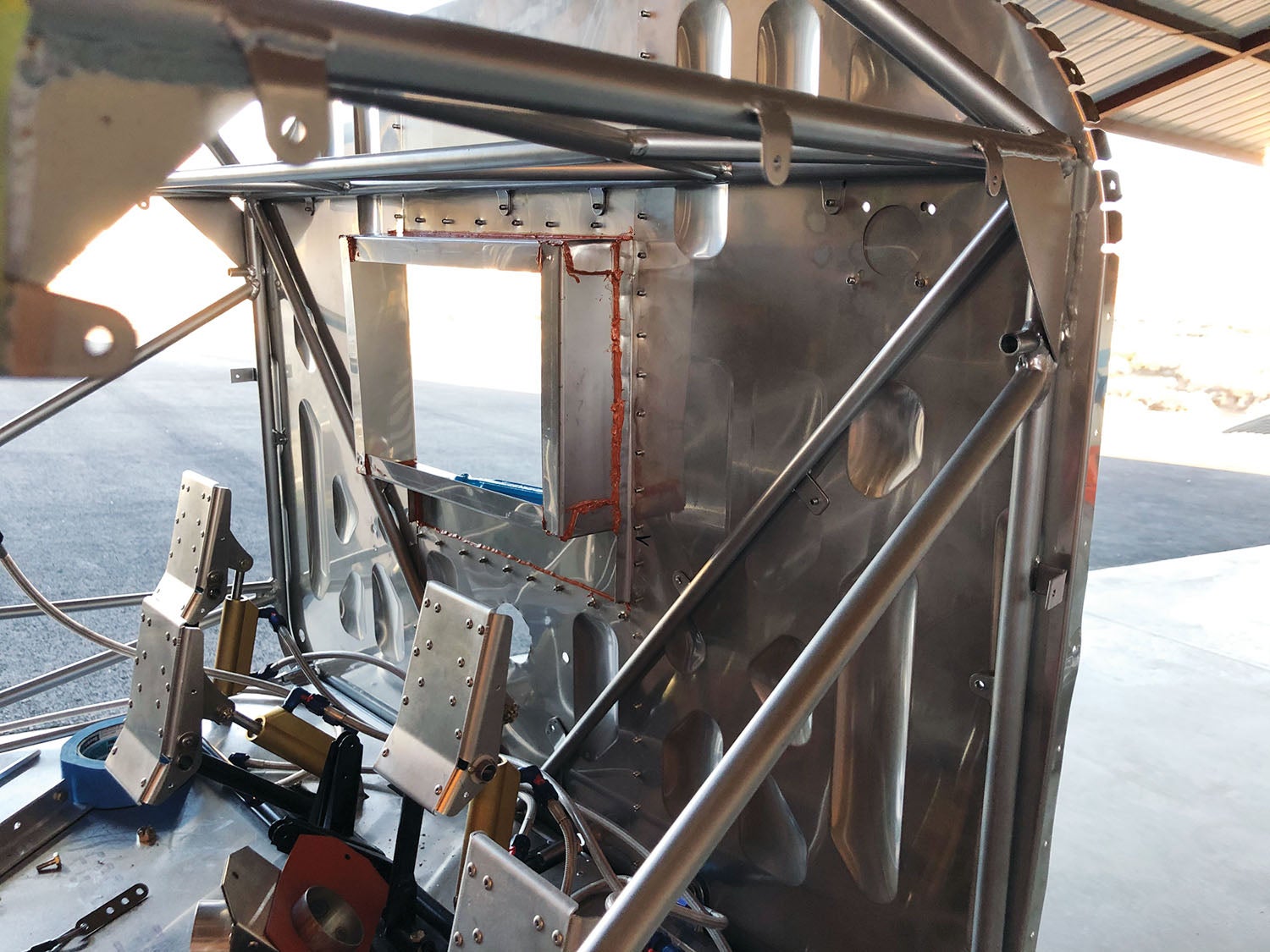
Once again, reassurance from other neighbor builders that this is not an uncommon practice. Stainless steel, like the firewall, is used to build the doghouse and any “holes” in the firewall are reinforced with a fire-retardant silicone sealant called Fire Barrier 2000, which is made for high temperatures.
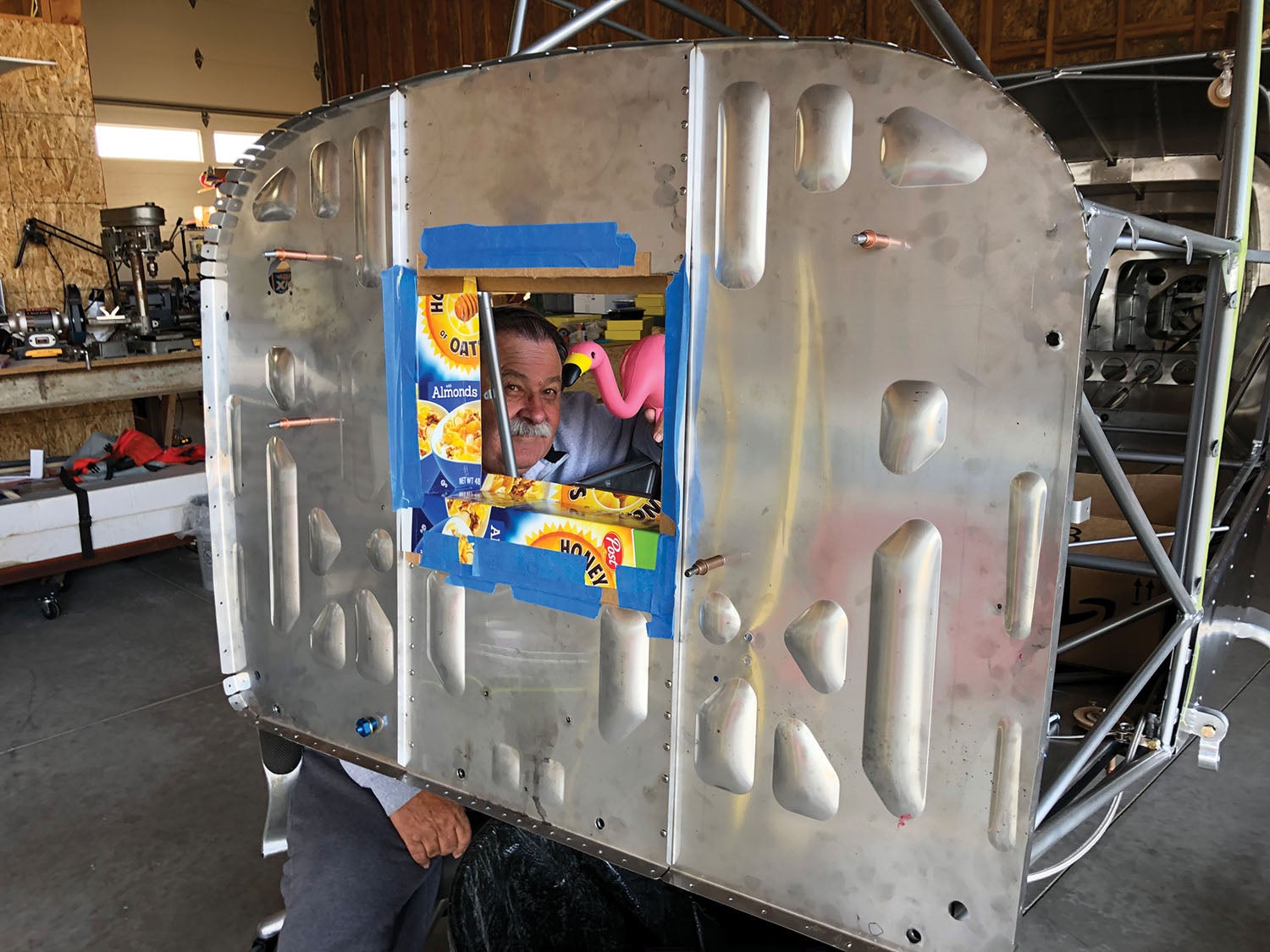
Because there were no plans for this doghouse, Mike made a pattern for the stainless steel pieces out of a cereal box. The exact location and measurements were borrowed from another S-21 builder off the RANS builder Facebook site. (Another reason a vital builder community is so helpful.) As I later learned, there are a lot of things that get attached to the firewall and holes to be punched in it to accommodate wiring and hoses. I was less stressed about cutting holes, including one big one, once I realized that this was “normal.”
Be Cool
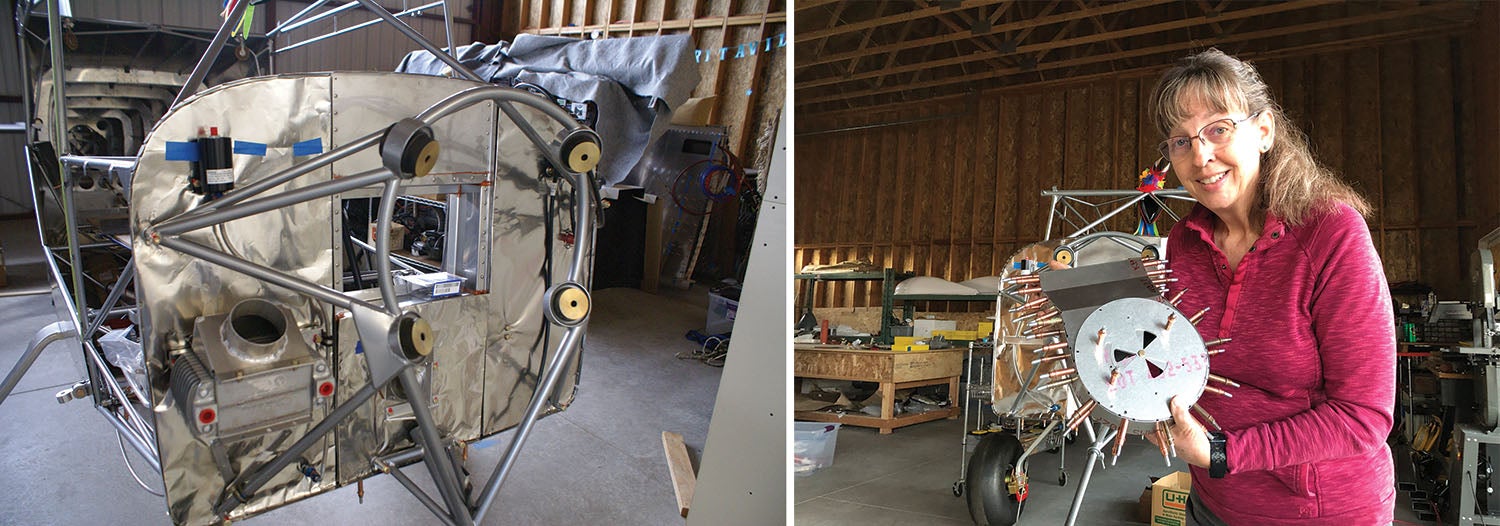
We weren’t close to done on the firewall, and that was good, because Mike took the opportunity to add a layer of insulation on the engine side of the firewall—to reduce heat coming into the cabin and noise. He cut pieces of a material called Fiberfrax, which is a ceramic insulation blanket, and then cut pieces of stainless steel foil (0.003-inch thick) large enough to capture the Fiberfrax blanket, then covered the forward side of the firewall with these pieces. This Fiberfrax stuff is pretty amazing in that you can cover your hand with it and put a blow torch to it and your hand won’t even get warm. Mike demonstrated this, but I’m not trying it!
One side job that Mike put me on was to “go build the air filter box.” I looked it up in the parts and text manuals, pulled together all the pieces and built it! I thought that was pretty cool. I know it wasn’t a big deal, but it was nice for him to give me a job and I figured it out and did it!
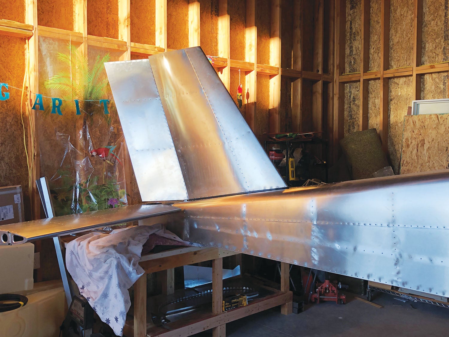
Tales of the Tail
Now it was time to get the tail pieces on. Unknowingly, we were working from an older version of the builder manual. Both Mike and I had read through it and came to the same understanding that we were to mount the vertical stabilizer first, then the horizontal stabilizer and finally the rudder. Through much anguish we were able to get the vertical stab on. It is the perfect case for tiny hands and dexterity, thus I had the brunt of the work getting the nuts and bolts lined up and tightened down in this space that is nearly impossible to get to. What a bugger!
The horizontal stab was not as difficult to get attached, but then we discovered that the rudder could not be attached. What went wrong? I was super frustrated and we called it a day. Sometimes you just need to sleep on it to figure things out.
Mike got to poking around on the computer and discovered that the “revised” version of the manual was a bit more clear, stating that “the rudder must be installed onto the vertical stabilizer before the assembly is installed and that the horizontal stabilizer needs to be installed first as it will not clear the rudder.” Another ugh. It was totally “our bad,” but take this as a helpful hint to all builders: Make sure you are working off the most recent version of the manual to save yourself time and frustration.
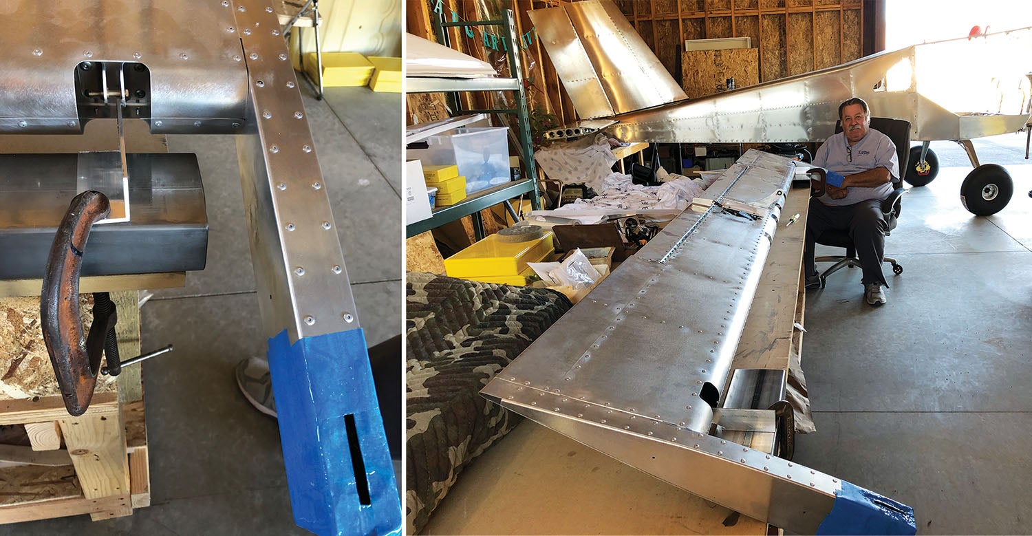
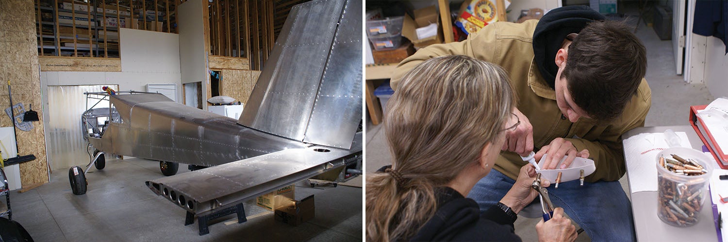
The next and final tail piece to get attached was the elevator. I never realized that there is a “balancing” act that needs to be done with this part. Mike had one of our work tables in the hangar set up to accommodate a fixture so that the elevator would be suspended on each end, free to move, and then we would put lead shot in these holes on each side of the elevator arm. After the balancing, we mounted the elevator to the horizontal stabilizer and got the tips in place with the assistance of our son.
There is so much that goes on with building a plane that it is rather mind boggling. I am learning so much during the build of this plane—not only how much time and effort it takes but a respect for the knowledge and ingenuity involved in the process. It is not a turnkey process. If you want that, you’re better off with a manufactured airplane and hiring someone else to work on it. But the homebuilt gives you so much more besides building it just the way you want it, though this is no small advantage. At the end, you’ll have completed a sometimes difficult but immeasurably rewarding experience.
Editor’s Note: Laura and Mike will be taking another one-issue break in this series to catch up on a few projects with the RANS S-21, but they’ll be back for the March issue.


Mike and Laura: I saw your nose gear strut and immediately thought of my friend’s RV-8A and the tumble he almost took after running through a patch of soft sand on landing. He and his airplane and his engine and prop were saved by his anti-splat reinforcement bar. I immediately installed one on my Glastar trike setup. If you’re going to be operating in the back country, please, please look into it.
Comments are closed.