There is a reason that most popular kits these days use fiberglass cowls. Old-style metal cowls (as found on most popular certified singles from the past 60 years) are notorious for wearing out due to abrasion and cracking. The vibration environment surrounding our old tractor motors is such that every cowl is in a constant state of self-deconstruction, and at least the fiberglass ones can be fixed with a bit of resin and glass. Metal cowls take a little bit more of a traditional repair solution: metal patches.
Cracks in metal cowls often occur where parts are being pulled together (or apart) in ways that contradict the natural way that the metal wants to sit. Anywhere stresses are being applied that change the direction of pull, there is a significant concentration of stress. As such, a minor nick or gouge on the edge—of a hole or a sheet—will serve as a starting point for a crack. Many cowls have reinforcing doublers at known stress points precisely to prevent cracks from forming. Often, they don’t work—instead, providing rivet holes where cracks actually can start.
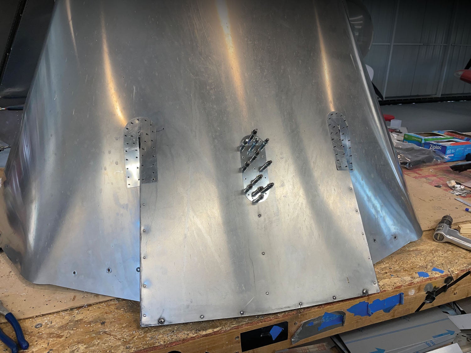
Such was the case with the metal cowl that came through the shop recently. Its design has the exhaust tunnel dropping down from the center of the bottom cowl, with two riveted-in wedges forming its sides. Reinforcing doublers were factory installed at the front corners, but the stress of motion was too much for them to hold—the doubler plates themselves were cracked, and stress risers had gotten to work on the cowling itself. In addition to this, a stiffener riveted to the center of the tunnel was creating a significant stress point at its forward-most rivet, and a crack was propagating laterally (left and right) from the center of that hole. We’d watched and stop-drilled these cracks over several annuals, and it was clear that more aggressive repairs were going to be needed.
Double Time
A patch is really a doubler—and a doubler might be thought of as a patch. In either case, you are adding a piece of aluminum on top (or beneath or both) an existing surface to add strength. Whereas the parent material might have cracked or been subject to forces beyond what the single sheet can handle, adding the patch or doubler transmits forces through the rivets to share the load, making the structure stronger in just the places necessary while keeping the rest of the structure light and thin. In the case of an actual crack, you can think of the doubler/patch as a splice plate.
Advisory Circular 43.13-1B, Section 4 is your guide to repairing metal structures. It can be a bit difficult to find exactly what you are looking for, but a read-through of the entire section is a good place to start—this will familiarize you with the basics and show you a few pictures that are valuable when laying out a repair. But to save you time, the real heart of the matter of skin repairs can be found in Figure 4-16, which shows examples and gives information for numerous types of patches. This figure, in combination with rivet spacing data from Tables 4-9, 4-10 and 4-11 should give you most of the information you will need.
Drilling the Old, Planning the New
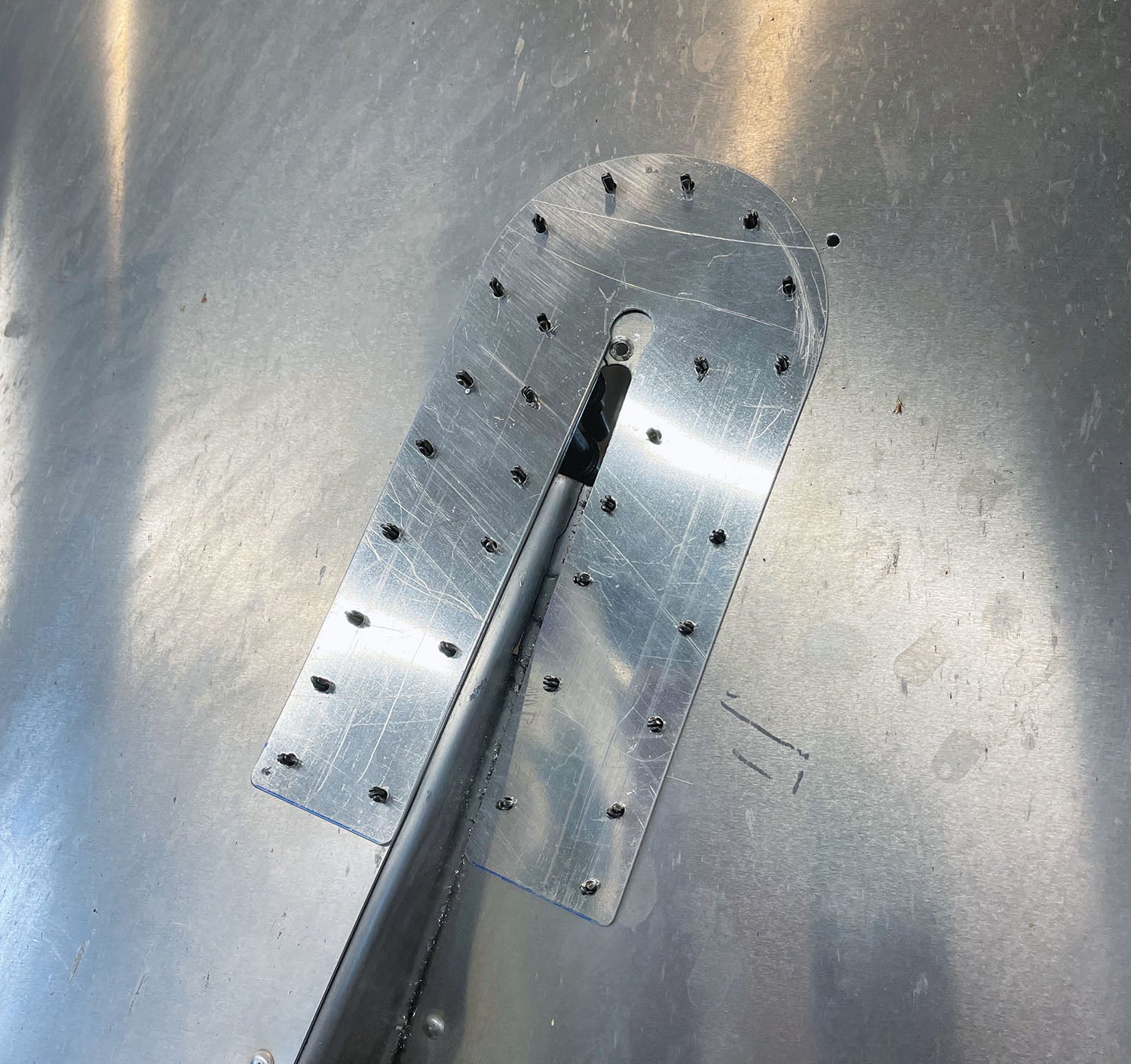
The first step was to drill out all of the rivets holding the remains of the old doublers and a couple of the rivets holding the center stiffener to give us a flat place to mount a doubler. Drilling out rivets is an art that you learn along the way—by drilling out a few thousand rivets. Round-head (standard) rivets are the most troublesome, but a sharp bit on your drill motor and careful “steering” at the start should allow you to get the heads off the outside then pop out the shanks.

You can also buy special tools to help center the drill bit on the rivet head dome if you like—some work better than others. However you do it, if you feel that the holes are just too buggered up when you’re done, plan on upsizing to the next size rivets when you reassemble. Note that this will increase your edge distance requirements, so plan ahead!
While you’re drilling out the old doublers, make sure to look at any cracks in the parent material and make sure that they are stop-drilled. The most common mistake I see in stop drilling is not getting the hole at the true end of the crack—you ideally want the center of the hole at the end, and the end is always a little beyond what you can see with the naked eye. If you don’t get the crack end totally within the hole, you haven’t stopped the crack, and it will continue to grow—probably beyond your patch.
One further consideration is if you are fixing impact damage that has actually torn or otherwise displaced the original material, you might want to cut out the old material and either have a “cover patch” that covers a hole or an insert that fills the space and the patch covers and supports. See AC-43.13 for these cases.
Laying Out the Patch
Laying out a patch should be done in accordance with the guidelines in AC43.13 when no manufacturer’s data exists. Granted, the illustrations in the AC are generally showing you how to repair the structure in a T-6 or B-17 (they haven’t updated the illustrations in a very long time), but basic guidance for rivet spacing and patch overlap can be found in those pages.
One way to do a reasonableness check on what you get from the AC is to take a look at doublers on other parts of your airplane and check the rivet spacing there, as well as to have a look at the spacing on your parts in general. As a rule of thumb, if you use similar spacing—not too much wider, not much closer—you will find that you have an acceptable patch. Remember to allow sufficient overlap of the damaged area to completely cover the cracks or damage and to allow the new outside rivets to be outside of the damaged area by the same edge distance you will use between your outer rivets and the edge of the patch. If you follow those rules, you’ll pretty much satisfy AC43.13 as well.
For patch material, the simplest thing to do is to use the same thickness of material that you’re fixing, as well as the same alloy and temper of aluminum. This is when it is handy to know if your plane is built from 6061-T6, or 2024-T3—or something else. Check your original build documentation and use what the factory used. The idea is to make the patch carry all the loads in the cracked or damaged area, and if you use the same material as the factory, the patch material should adequately support those loads.
In general, you can use the same size rivets as are used in the general structure in the area that you are repairing, unless you are trying to reuse existing holes that have been oversized by the process of drilling out rivets, in which case you might have to go up a size. This is a good argument for carefully drilling out the originals—or just drilling all new holes and covering the old ones with the patch.
The Case at Hand
We had to make three patches, two of them mirror images of each other. Because the cowling had shown a particular tendency to eat itself where the forward corners of the tunnel began, we decided to make a sandwich doubler—both an inside and an outside doubler, with the skin in between. This meant we needed four doublers. We decided to use the original factory doubler as a departure point, staying with its basic shape but making it longer to ease the transition from the main cowl surface to the exhaust tunnel.
Then we had the center patch, which was covering a crack emanating from a reinforcing stiffener’s front rivet. Anticipating further cracking, we decided to make it longer than might appear necessary, but in so doing, we could spread the stress over a larger area, hopefully preventing further cracks from developing.
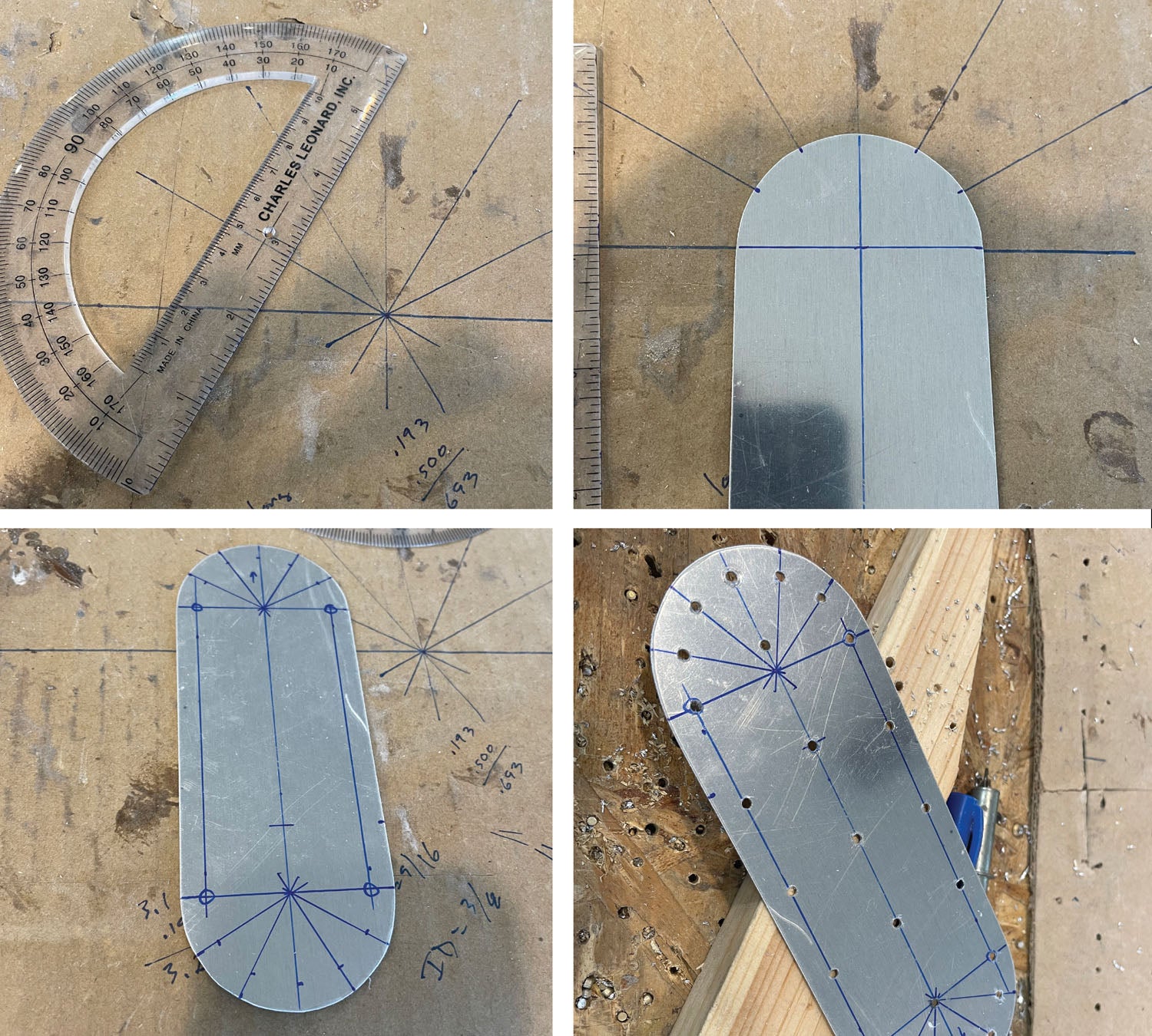
After deciding on the basic shapes for the doublers, it was a matter of laying them out on the aluminum sheet we had handy, then using the shear to make blanks, the band saw and sanding disk to execute the curves and the Scotch-Brite wheels to smooth and deburr all the edges. It doesn’t do to introduce stress risers on doublers designed to spread out stresses!
Rivet holes were laid out to match those on the original doublers for spacing and angular separation, and the same basic pattern and spacing used on the center doubler for consistency and some semblance of “art.” A protractor, rule and rivet fan made the process quick and easy—then the holes were drilled in the patches.
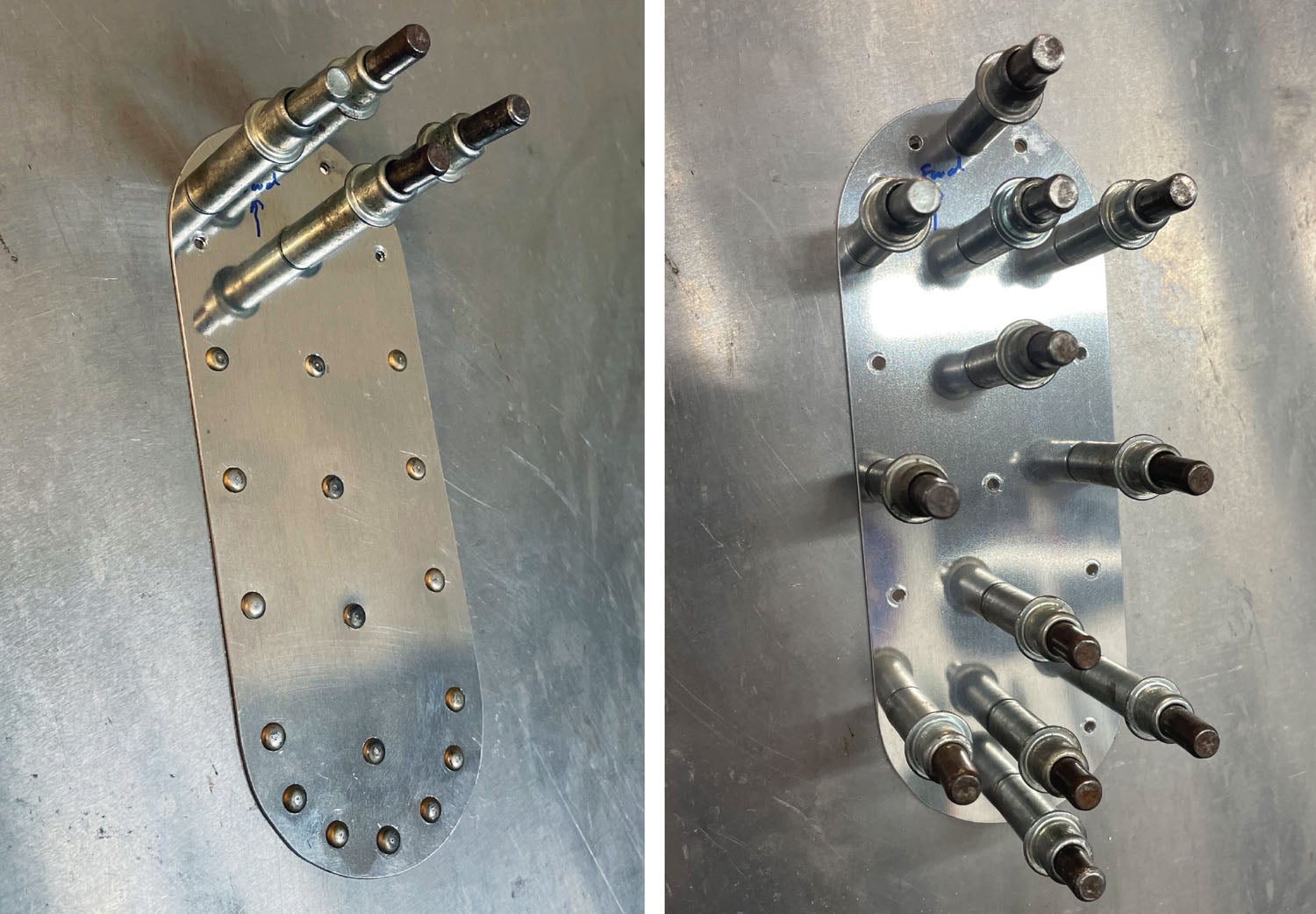
Finally, with the predrilled holes, it was a simple matter to drill a couple of positioning holes in the cowling, Cleco the patches in place, then complete drilling all of the holes. As with all metalwork—drill, remove, deburr, Cleco back together and check the fit.
Because the doublers and repair sites were well away from the edge of the cowl, squeezing the rivets wasn’t a choice. So out came the rivet gun and a tungsten bar. An hour or so later, all the rivets were in place, and the job was done!
Patches Buy Time
Let’s be honest—no one really likes the idea of their pride and joy homebuilt having patches in areas visible to the public. But, sometimes, a patch is necessary when you find a crack and want to keep flying until you can replace a cowling or a fairing. Sometimes lead times or costs for a major component are such that a patch is the easiest way to stay in the air until you source (or can afford) the replacement. And fortunately, most of our modern designs are using composite parts in these difficult areas now anyway. But older designs still get built each year, and the art of making an aluminum patch is a handy one to have—you never know when a crack might appear.
Want to see more of Paul’s metalworking tips and tricks? See all of his 24-part series on working with metal.


I’ve had good success stop drilling the crack and laying up a fiberglass patch on the inside of the cowl. A couple layers of fiberglass cloth and some epoxy resin stiffen the area surrounding the crack and prevent further propagation. And, the repair is less obvious from the outside.
Comments are closed.