As many fabricators will admit, there’s something mysterious and magical surrounding the English wheel. While teaching an aluminum-forming workshop at AirVenture, as I was tracking over 3003-H14 .063-inch aluminum, passing the material back and forth through the English wheel, an individual commented, “That machine is like a Ouija board.”
Indeed, as the metal begins to stretch and form a dome, it does seem to take on a life of its own. But when the workshop attendees try their hand at tracking, they quickly realize this isn’t magic—it’s a skill. With practice, the English wheel makes it possible to transform flat sheets of metal into finished parts with compound curves.
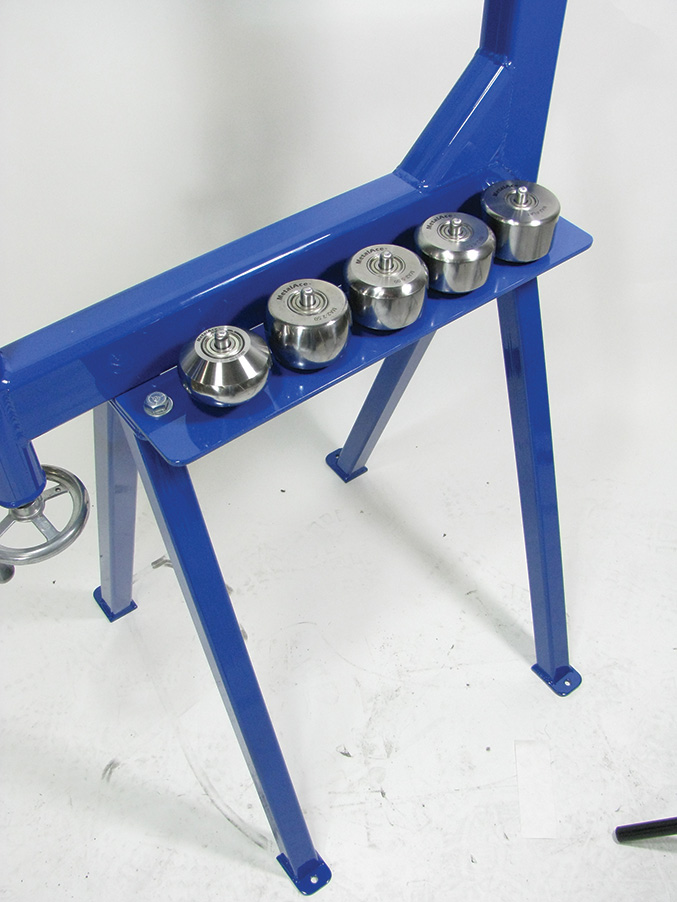
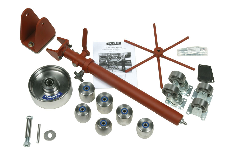
Anvil wheels are available in a wide range of radii. From left to right: 2.50r, 3.75r, 6.00r, 12.00r, 24.00r and flat radius.
Easy as Pie
English wheels have been in existence for over 100 years. They are commonly used in the United States in the custom car and aircraft industry. But how do they work?
Imagine a baker is making a pie crust. (In our case, we’re making a fairing or wheelpant.) As the baker mixes the ingredients, dough is created. (In metal forming, flat sheet aluminum or steel is the dough.) The dough is transferred to a flat counter, sprinkled with flour, and rolled out using a rolling pin. (In our case, the English wheel is our rolling pin.) As a baker rolls the dough, it becomes thinner and wider. (As we track with the English wheel, the aluminum or steel becomes thinner and longer.) The shape we create is determined by our anvil wheel selection and the amount of pressure we apply. (We’ll look at this in greater detail in a few moments.)
English Wheel Basics
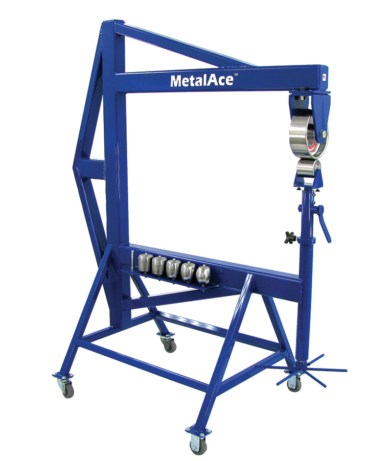
An English wheel can be broken down into four major components: frame type, roller wheel, anvil wheel, and adjusting mechanism. The photos show a fabricated benchtop style machine. Notice that the frame looks similar to a “U” or a “C” shape. This machine is referred to as a fabricated benchtop style because the machine is manufactured using square tubing, rather than cast iron. Although many styles of English wheels are in use, the fabricated benchtop style is the most common. Versatile yet affordable, these machines suit any skill level.
The benchtop frame is produced by cutting mild steel tubing to size and welding it together in a welding frame. This assures the frame will be square when finished. Benchtop style machines can be mounted in a vise or placed directly on a workbench or floor stand. Stiffener braces may be added to keep the frame from flexing while working with 16-gauge material or thicker. A common misconception is that the frame needs to be completely stiff. While some stiffness is required, the material you are shaping responds to the pressure exerted between the roller wheel and the anvil wheel.
Another style of wheeling machine is the fabricated floor model. This style offers a larger throat depth (the distance inside the U- or C-shaped frame), making it possible to shape larger panels. Obviously, the larger throat depth means a larger footprint (the space the machine requires in the shop). We will take an in-depth look at floor model machines in a future article.
Some manufacturers also offer “U-weld” kits. With this type of kit, you supply the material for the frame, and the kit includes the lifting mechanism, roller wheel, a set of anvil wheels, and a detailed instruction manual for construction. This is a great way to save a bit of hard-earned money, while using your own frame design and welding skills.
Speaking of costs—like any hobby equipment, the price of an English wheel will vary. They may be purchased for as little as $300, or you can spend thousands of dollars; bear in mind that cost is relative to quality.
Just Roll with It!
Are you thoroughly confused yet? Thus far, we have discussed what the English wheel is and how it works. (Remember the baker and the pie dough?) We know that the U- or C-shaped frame can be manufactured from tubing or cast iron. And we looked at fabricated benchtop and floor model machines.
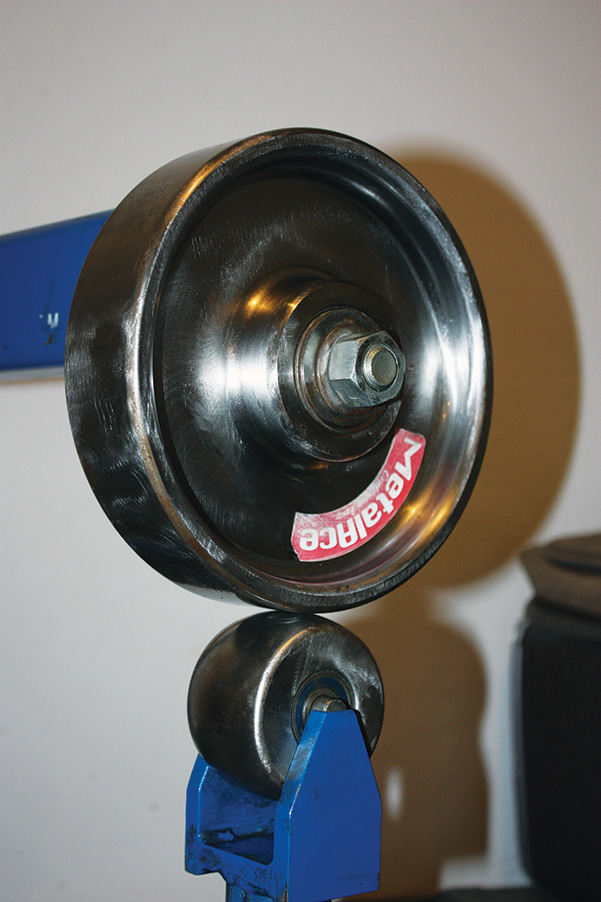
The next component we’ll cover is the roller wheel, sometimes referred to as the top wheel. This wheel is manufactured from 1045 steel and measures eight inches in diameter by three inches wide. The width of the roller wheel may vary from manufacturer to manufacturer, but the surface will always be completely flat, unlike the anvil wheel, which is usually domed.
The roller wheel may be mounted on an axle (benchtop model) or, in the case of a floor model, a yoke (a U-shaped wheel holder). One advantage of the axle mount is that the craftsman is able to rotate the wheel by hand, allowing better control in a confined space. The roller wheel will spin freely 360 degrees.
The next item we’ll look at is the anvil wheel, often referred to as the lower wheel. Like the roller wheel, it is manufactured from 1045 steel; however, the dimensions are likely to vary. The anvil wheel is always mounted on the lower C- or U-shape of the machine in the yoke. Pressure adjustments are made between the anvil and roller wheel by way of the adjusting mechanism. The adjusting mechanism is comprised of an Acme screw and a handwheel. To increase pressure, rotate the handwheel clockwise; to lower the pressure, rotate the handwheel counter-clockwise. A press-fit roller bearing on the inside diameter allows the anvil wheel to spin smoothly. A precision-ground pin acts as the axle the anvil wheel rotates on. The benchtop machine uses a two-inch wide anvil wheel. Floor models use a three-inch-wide anvil wheel.
Now we move on to the radius of the anvil wheels. Radius doesn’t refer to the diameter of the anvil wheel. It refers to the curve of the surface on the edge of the wheel. Benchtop machines usually come with a 3.25-inch radius anvil wheel only. Wheels with a 1.0-, 2.5-, 5.0- or 8.5-inch radius are offered in a complete set or individually for purchase. Flat-radius anvil wheels are also available.
Two questions I’m often asked are, “How many radius wheels do I need to have on hand?” and “What radius do I use for a particular application or project?” These are both great questions and we will look at them in detail in future articles. My usual recommendation is to purchase a complete set of wheels, both for initial cost savings and to increase a machine’s capability. I would be disappointed if my motivation showed up on a Saturday night, only to find I did not have the correct radius anvil wheel for the job.
With a “U-weld” kit, you supply the material for the frame, and the kit includes the lifting mechanism, roller wheel, a set of anvil wheels, and instructions for building the frame.
Plan Your Track, Track Your Plan
We now have an understanding of the roller wheel and the anvil wheel. And we know there are many anvil wheels to choose from. It’s not difficult to see how the material begins to take the shape of the anvil wheel selected. As pressure is added, the metal stretches and begins to dome upward.
To achieve a uniform stretch and dome, you must decide what tracking pattern you will use. This also ties into “steering” the English wheel. One of the most common tracking patterns is often referred to as the “lawn-mowing” method. As the name implies, you pass the material back and forth, from one side of the panel to the other. You can move from the left to the right side of the panel; or you can move from the right to the left. I encourage beginners to spend plenty of time on this step. Purchase your first sheet of material and dedicate most, if not all, of this material to familiarize yourself with the machine. Characteristics of “steering,” die selections, and pressure settings of the machine will be greatly enhanced with more practice.
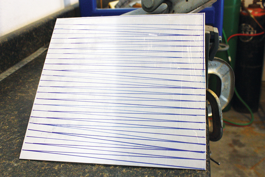
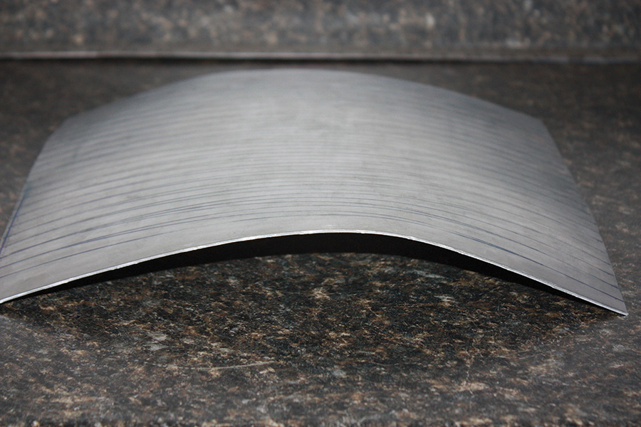
Layout lines are spaced one-half inch apart on this one-square-foot piece of 3003-H14 .063″ aluminum. Notice the diagonal tracking lines between the layout lines.
Follow these steps closely:
1. Shear a one-square-foot piece of material.
2. Using dots, lay out 0.25-inch to 0.50-inch lines both fore and aft and left to right.
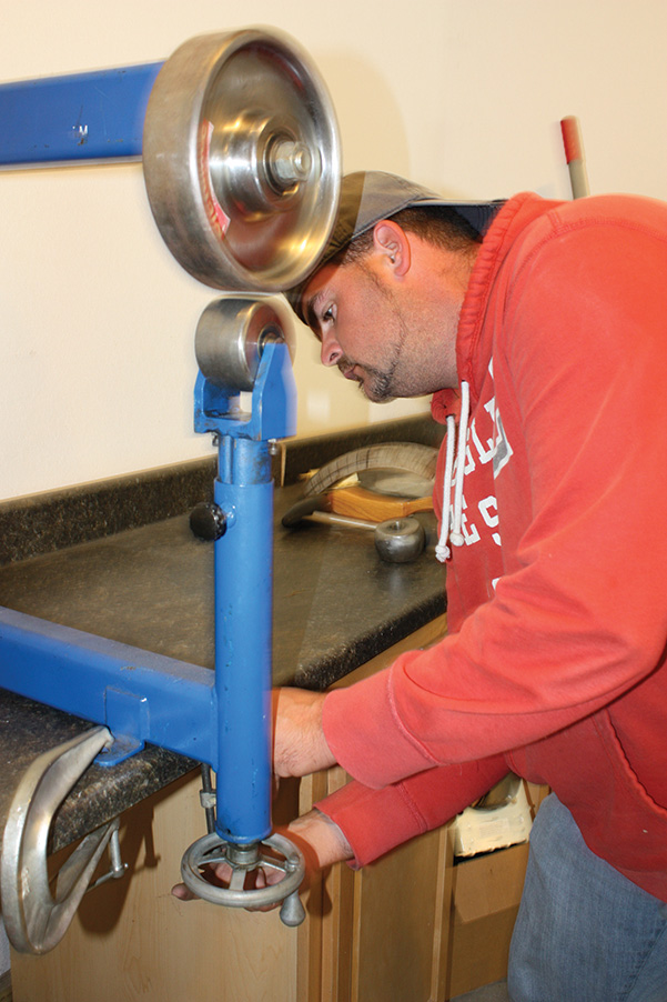
Moving the adjusting mechanism handwheel closes the gap between the roller wheel and the anvil wheel.
3. Now connect the dots with solid lines between the fore and aft. (Do not connect the dots from the left to the right.)
4. You now have guidelines to track.
5. Choose an anvil wheel and install it into the yoke of the machine.
6. Close the gap between the anvil wheel and the roller wheel; insert your material and begin tracking.
Once you work from left to right, repeat the step from right to left. Pay particular attention to your tracking; you do not want to track too far fore and aft and run off the material. After this is completed, turn the panel 90 degrees and repeat the aforementioned step. You have just completed your first set of tracks.
See, that wasn’t too difficult. In addition to your first set of tracks, notice that your one-square-foot piece has shape in both directions—fore and aft and left to right. Also notice that the center of this piece has risen about 5/8 inch. This is because you have stretched (and thinned) the material with the wheel.
Other tracking techniques include a star pattern for round pieces, and the staggered stop technique for larger panels. Resist the temptation to tackle extremely complex shapes at first. This will be a frustrating experience and may cause a complete loss of interest in future shaping projects. As you become proficient, tracking will become second nature. This early stage is when you will need to practice and refine your skills.
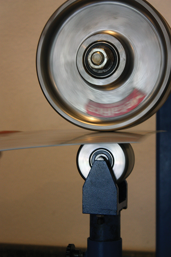
Beginning the lawn-mowing tracking pattern; low pressure settings control the amount of “stretch” in the work.
Keeping your part symmetrical and smooth is of the utmost importance. Make sure that you are following your guidelines and make subtle adjustments as necessary. If you notice too much crown in the center, you can wheel around the edges to raise that area. You cannot take the shape out of a part by flipping the panel upside down and wheeling over that area.
From time to time, you may need to pull the material out of the English wheel and readjust the panel on the bench. Push the sides and edges down, or twist them for a bit of adjustment. Again, the more you practice, the more proficient you will become.
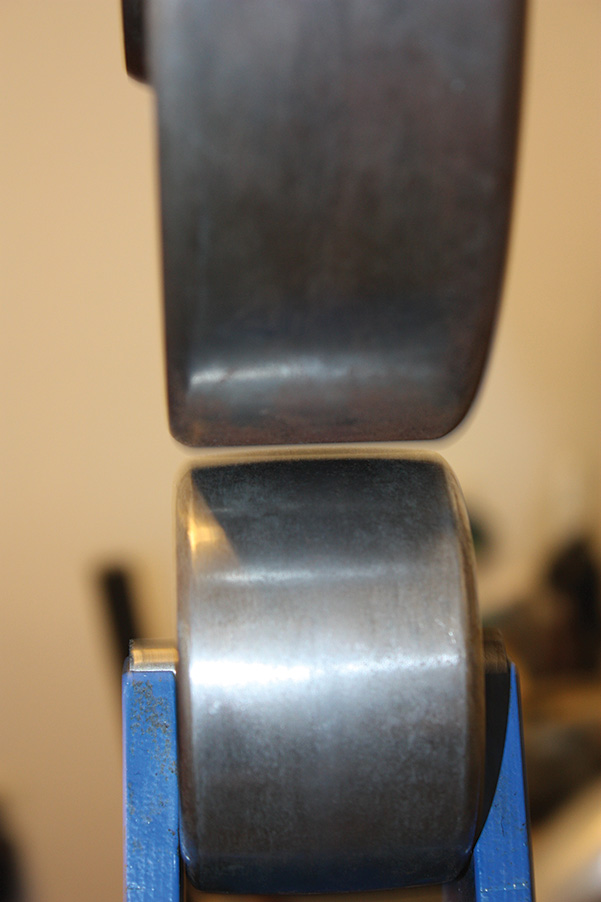
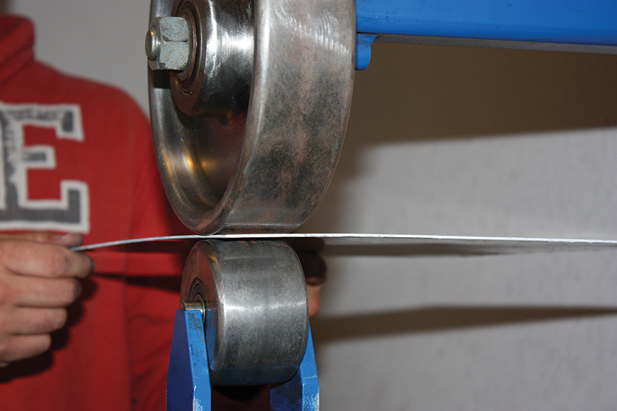
Look closely at the aluminum between the roller wheel and the anvil wheel. You can see a subtle dome in the material.
Learning with Ron Covell
Now that you understand basic tracking patterns, and what problems to look for, what can you cut out and shape? A great resource and an individual that I have learned a lot from is Ron Covell. Ron offers workshops throughout the United States, as well as internationally. I recommend purchasing his video entitled English Wheel Techniques. This video is a great companion to the workshop. You can walk through the process on your own English wheel as Ron demonstrates each fundamental task. Check out www.covell.biz for a complete list of workshop locations. Also keep practicing on simple projects. There is nothing mysterious about the English wheel, once you see what it does and learn how it works.

