My day job involves wiring and configuring instrument panels for new Light Sport Aircraft. Lately, we’ve been using the G3X Touch system from Garmin and really enjoying it. In many ways, the Garmin system is more sensitive and advanced than avionics we’ve used in the past, so even though I’ve worked with it for a while, I still had questions about the best practices for installing it. When Brian Hupe of Garmin’s Team X told me that the Aircraft Electronics Association (AEA) was now offering a course on installing Garmin G3X avionics in Experimental aircraft, I said “Sign me up!” The course is fairly new, so I didn’t know what to expect, but I was not disappointed.
AEA Goes Experimental
Based in Lee’s Summit, Missouri, a suburb of Kansas City, the Aircraft Electronics Association is an international organization of nearly 1300 member companies involved with avionics and electrical systems in general aviation aircraft. AEA members include avionics and airframe manufacturers, certified repair stations, major distributors, and aviation schools.
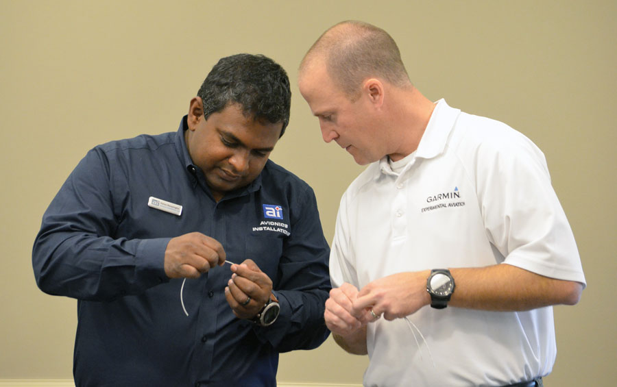
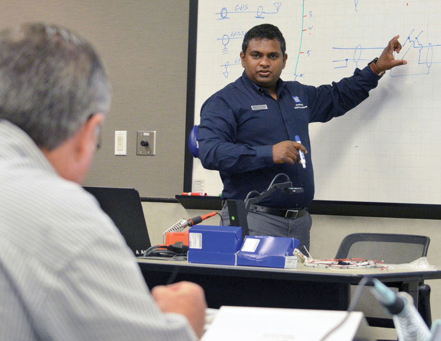
Course instructor and experienced G3X Touch installer Pahan Ranasingha answers a question for Brian Hupe, sales manager for Garmin’s Experimental division. Brian attended the class as a student, learning how to wire the system as he prepares to finish his own RV-7.
Mike Adamson, AEA vice president of member programs and education, says the organization has been offering courses for basic wiring and avionics installations for about 15 years. “The AEA is unique in that our instructors are experts who own and operate avionics repair stations or are field-service engineers with major avionics manufacturers, so they have real-world experience, up-to-the-minute knowledge of advancements in technology, and access to the latest technical publications.” Based on my experience, he’s right—they know their stuff and are eager to share their experiences through quality instruction.
The three-day Garmin G3X Touch installation class is the result of AEA reaching out to course instructor Pahan Ranasingha, owner of Avionics Installations, Inc. of Port Orange, Florida, who organized a new course for installers of Experimental avionics systems. Garmin is a regular supporter of AEA courses, and the popularity of its Experimental G3X system is opening new doors for the organization, which has traditionally focused on the certified world.
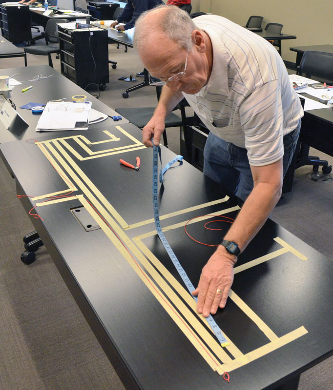
One of the tricks of building a custom wiring harness is laying out a full-size template with masking tape on your worktable.
Class Notes
About a week before the class started, I received an email with some homework. Yup…homework. It consisted of examining about 90 pages out of the G3X installation manual to give attendees a solid background in what the course instructors are trying to accomplish. The moment I read that email, I was thrilled…I’d already studied all that stuff, and I paid the money for the class to get more than what the manual offers. And Pahan delivered, with three long days of lessons from his own experience that explain what’s in the manual and well beyond.
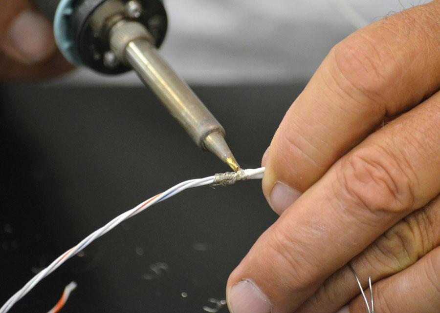
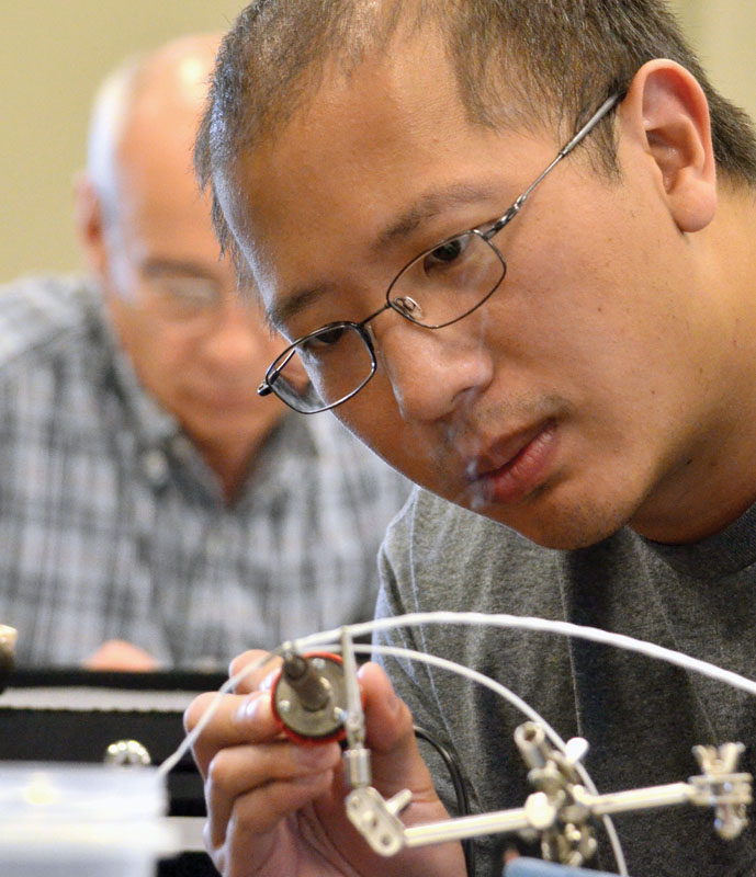
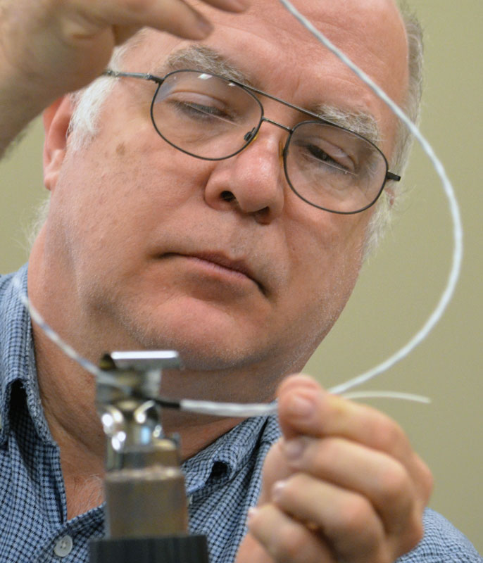
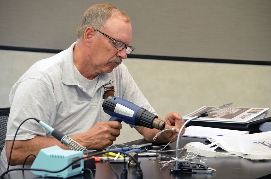
Soldering a shield drain is one of the most important building-block skills in installing a Garmin G3X Touch system, as well as many other types of avionics.
From the moment the class started, Pahan put us at ease with his confident knowledge and occasional funny comments about things he’s seen. His rsum is impressive—as an A&P/IA and the owner of Avionics Installations, Inc. since 2003, he has designed and implemented avionics retrofits and installations in dozens of certified and Experimental aircraft, from mundane GA machines to P-51 Mustangs; even a glassed-out de Havilland Chipmunk. And he flies a beautiful Van’s RV-7A that he wired himself—with Garmin equipment—IFR all over the country. He’s basically seen it all and is good at explaining complex concepts on a variety of levels. Pahan does not work for Garmin, and his company is a dealer for almost all the major brands of avionics, so from the first five minutes, it’s clear that the class is not just a cleverly designed Garmin sales pitch. Rather, he is here to share his knowledge of the system with those of us who want to know more about it.
Soldering may be a humble skill, but if you do it wrong it will make the difference between a reliable system and one that’s prone to issues as time goes on.
While some of the attendees had extensive experience wiring Experimental and Light Sport Aircraft, others were completely new to the wiring scene, wondering not only how, but if they should tackle the ominous project of installing their own avionics. When confronted with blank stares from those who didn’t understand a concept, Pahan was able to take a step back almost imperceptibly and catch us all up to the subject at hand. In one case, he started explaining how to use solder sleeves for shield drains when he heard a quiet “Uh…what’s a shield drain?” Without skipping a beat, Pahan patiently explained the science behind shielded cable in “broad strokes,” as he likes to say, drew some diagrams on the board, soldered an example using his overhead camera, and then let us try it ourselves at our stations.
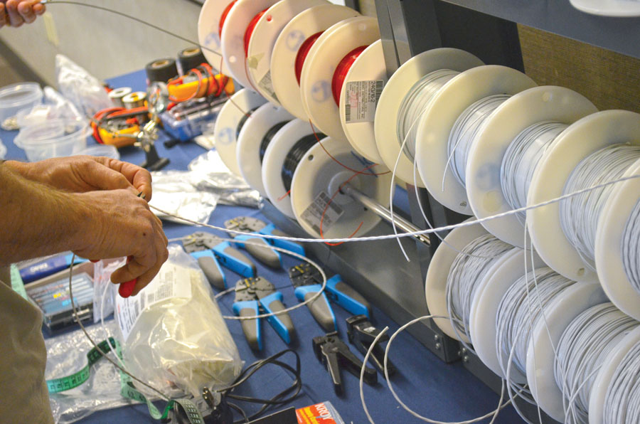
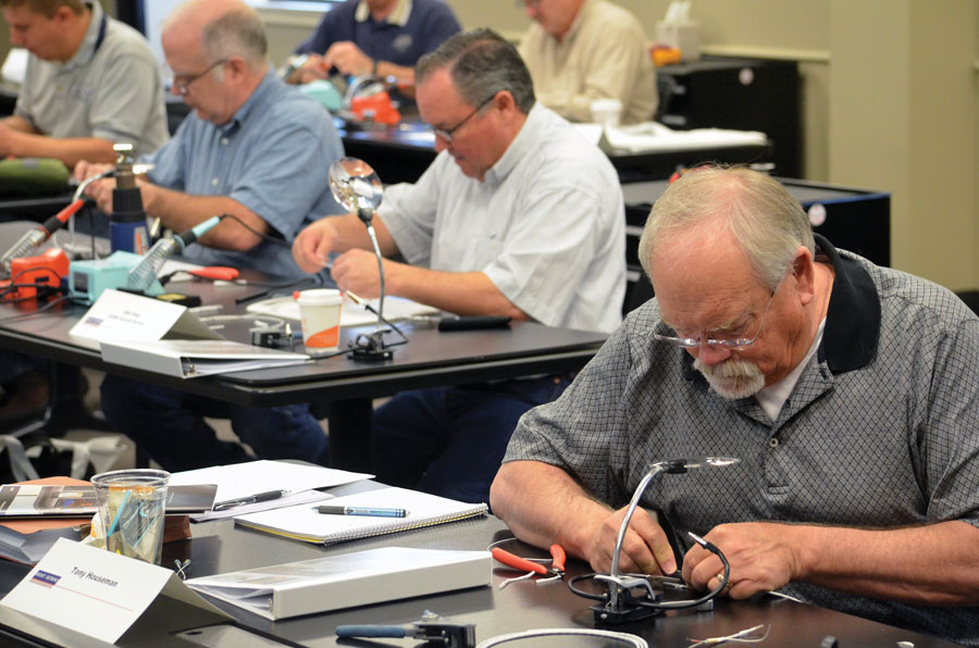
The course organizers didn’t skimp on quality when they provided a large selection of aircraft-grade wire, supplies, and tools for use in the classroom.
CAN (I really do this?) Bus
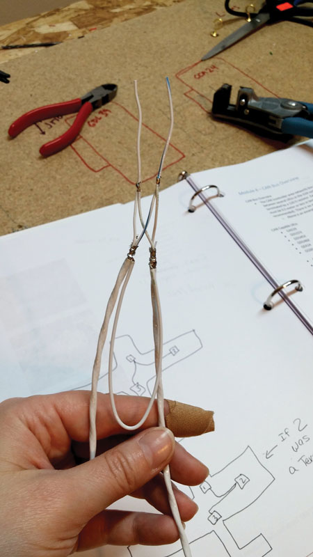
Class participants create a CAN bus node splice and small wiring harness to take home. The author keeps her CAN bus node in her toolbox as a reminder of how it’s done. Normally there’s heat shrink tubing on all exposed wire joints, but it was left off on purpose so the solder joints can be seen. (Photo: Katie Bosman Krotje)
Many aircraft builders don’t think about it during the EFIS brand decision process, but component communication is a major difference between the manufacturers. The Dynon SkyView and its AFS cousin use prefabricated cables and 9-pin connectors to form a “network,” while GRT uses simple unshielded RS-232 wires with programming options for each serial port. Garmin uses CAN (Controller Area Network), a data system widely used in large-scale avionics systems and modern cars. The CAN bus is the nerve center of the G3X system, the data path through which all the components communicate with each other. It connects the EFIS screens to the ADAHRS (Air Data Attitude Heading Reference System), as well as the remotely mounted LRUs (Line Replaceable Units), also known as the “boxes,” such as the engine monitor, radio, and autopilot servos. These units are often spread out all over the aircraft. The CAN bus data stream is run through a single cable that carries information for every unit in the system, and each box receives and transmits its own packet of data into the stream. This eliminates the need for cables from each LRU back to a central unit, such as the main EFIS or a network hub, saving weight, expense and (usually) trouble. The CAN bus can be backed up with an optional RS-232 connection between the EFIS, ADAHRS and engine monitor to provide a layer of redundancy.
Clarifying my understanding of the CAN bus was a major goal of mine as a student in the class. As of this writing, the Garmin G3X installation manual gives us several pages of drawings, specifications, and limitations, but very little guidance about what the finished product should look like. Black lines on paper don’t automatically translate to wire and connections, and the drawings left much to the imagination of the installer. At lunch the first day, some classmates and I discussed our mutual confusion over the proper way to physically construct the harness. I was happy that I was not the only one who felt intimidated.
Pahan reassured us that we weren’t idiots by pointing out some common mistakes people make when they interpret the wiring diagrams in the installation manual. One particular drawing has led many installers down a path where the “nodes,” the segments leading to each LRU, are much longer than they need to be; looking at the drawing, it was easiest to imagine a central “trunk” with wires branching off to individual LRU boxes. However, a continuous Christmas-tree-light daisy chain is a more appropriate metaphor, with the nodes being only a couple of inches long. The internal circuitry of each LRU ensures that if one LRU goes out, they don’t all go out. The Garmin engineers I’ve spoken with have insisted all along that it’s really quite simple…and they’re absolutely right.
The instant I saw the photograph of the simple soldered node structure in Pahan’s class notes, I said out loud, “Why doesn’t Garmin put that picture in the manual?” Pahan smiled. He understood my frustration, I think, and was glad to see this Christmas tree light finally come on.
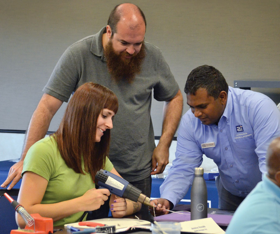
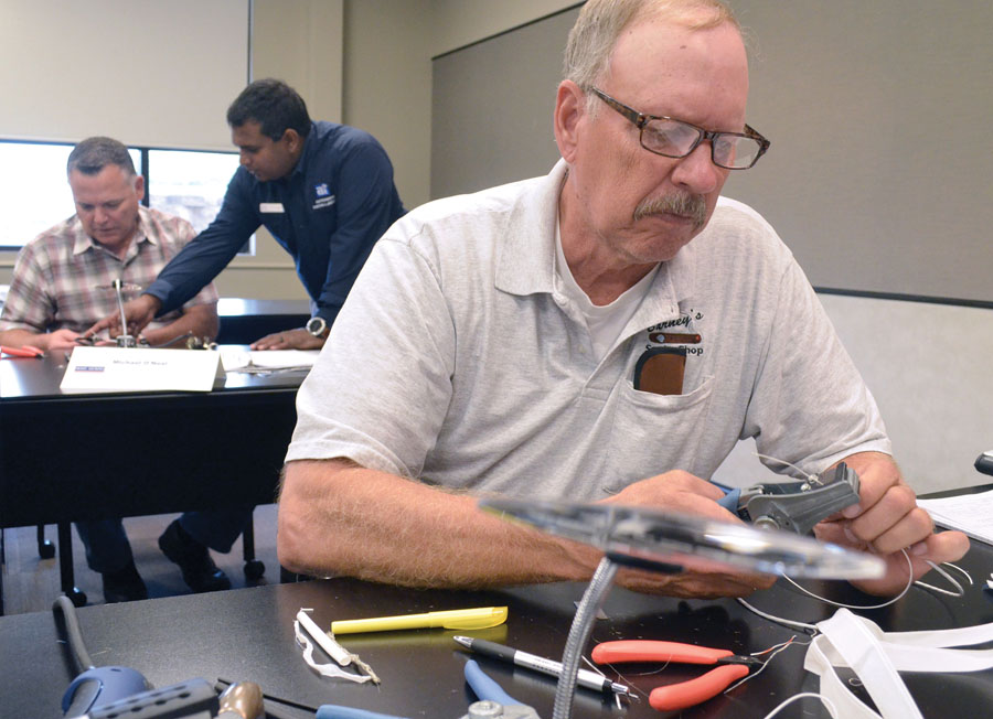
Instructor Pahan Ranasingha (background, right) offers one-on-one help to an attendee during the CAN bus node construction exercise, while another student works on his own to strip a wire.
Hands-on Experience
At the front of AEA’s nicely-appointed classroom, there was a long table with rolls of real aviation-grade wire and raw materials such as heat shrink tubing and cold-fusion silicone tape. The 12 of us sat two per table, and each table had a rolling toolbox filled with high-quality spark-chaser toys. As a junior-pro wiring nerd, I looked forward to seeing the tools that other professionals use, and I wasn’t disappointed. The tool box was filled with high-quality pin crimpers, wire cutters, wire strippers, soldering irons, and magnifying devices. Pahan told us about one of his customers who had over-crimped all the pins in the complex instrument panel of his homebuilt and later had reliability nightmares as, one by one, the wires fatigued and failed. So, of course, we paid attention as he showed us how to properly set up an adjustable pin crimper so we wouldn’t over- or under-crimp our own wire pins.
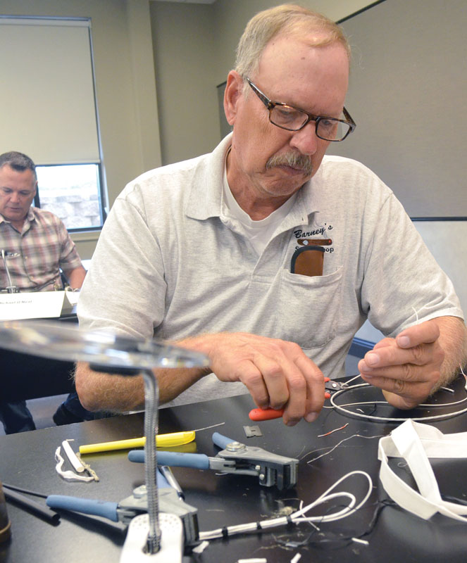
The hands-on portion of the class teaches attendees to solder their own CAN bus node splices for reliable data communication between the Garmin boxes.
Using his overhead camera, Pahan demonstrated the basics of stripping the coating off multi-conductor shielded wire. No fancy tools were required for that task, just a light touch with a fresh single-edge razor blade. He then showed us how to neatly and quickly solder a shield drain, which is a small wire that connects the shield to ground or to another shield in a daisy chain such as the CAN bus. This humble task is one of the building-block skills repeated throughout the entire G3X Touch installation, so it’s important to master early. And then, on the end of the first day, we all made our own little CAN bus splice. It’s amazing how such a simple little thing could build such grand confidence.
Einstein said, “If a cluttered desk is a sign of a cluttered mind, of what, then, is an empty desk a sign?” No empty minds in this class!
The second day of the class was spent unraveling the mystery of designing and building a custom wiring harness. Pahan shared his technique for measuring the distances between electrical items in the airplane, gave us examples of simple line drawings to record these distances, and then demonstrated how to transfer the measurements to a work table, effectively creating a full-size plan for the harness. Each wire is cut to length and added to the harness in a particular way. Organization is key! You just don’t know how quickly a few wires can turn into a massive furball until you try it. The whole class seemed to have fun on this task, working in pairs and helping each other through the little inevitable pitfalls. We also learned how to tie wax-coated lacing cord around our bundles to keep them neat—no cheap zip ties here!
The course gives attendees a chance to work with many tools, materials, and techniques of the wiring trade, such as solder sleeves.
Configuration and Troubleshooting
The class concluded with an extensive section on LRU mounting advice and configuration, and testing of the various elements of the G3X Touch system. As a pilot himself, Pahan can relate the mechanics of wiring and avionics installation to actual flight conditions, including features that we might find useful, common mistakes made in configuration, and precautions for safely flight testing the autopilot. He explained the procedures in the manual with the additional backstory of why each item is important—something that can potentially save installer/owners hours of miserable troubleshooting.
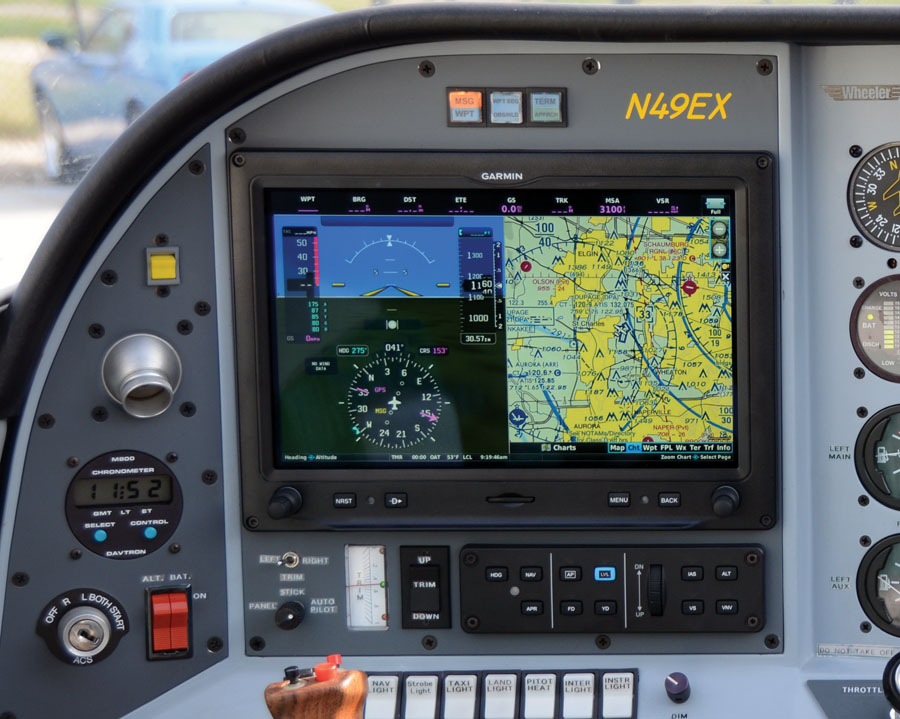
Reinhard Metz wrote about installing a G3X Touch System in his Wheeler Express in the October 2015 issue of KITPLANES. (Photo: Reinhard Metz)
Takeaways
While the course is built upon the Garmin G3X Touch system, the skills and concepts Pahan teaches are applicable across the entire spectrum of aviation electronics. Soldering, pinning, planning, shield grounding, wire-harness construction, security, testing, and anti-chafe techniques are all proven best practices in certificated and Experimental aircraft, so even if you decide to go with another brand of avionics, you will still learn important skills. Some people will walk out of there saying, “Wiring is cake, I can do this,” but others might decide it’s not something they want to attempt, and opt to hire a professional to tackle their panel. Either way, the $500 spent on the course can ultimately save you some time, money and frustration.
“The primary thing is education of technique and concepts,” said Pahan after the class. “I know that’s pretty broad, but if you think back to what we did at the class, the core was education on what the LRUs did and how they interfaced, and refinement of technique. Technique is where most builders get hung up. A good avionics installation isn’t just having every wire pinned in the right place. What makes an install good and serviceable is the skill sets we focused on in class: wire routing, proper terminations (crimping, soldering and shield drains), assembling connectors properly, securing and routing harnesses, and properly mounting LRUs. Most builders are capable of a professional install once they commit the time to education and apply what they’ve learned to their project.”
What’s next for the AEA team? The next class is still in the works, but Pahan hopes it will involve broadening the classes for Experimental and small Part 23 aircraft. “We are evaluating a two-day class that will cover core aircraft wiring: master buses, relays, avionics buses, basic charging systems, lighting and dimming, that sort of thing. The Experimental avionics installation class, as well as the other basic and advanced installation classes at AEA, make the assumption that you already have a powered and running airframe, but this class will take a green airframe and energize it.” Thanks to the efforts of Pahan and the AEA, the future looks brighter for the amateur-builder community already.
For more information regarding AEA classes and schedules, visit www.aea.net/training.

