“The only thing cheap in aviation is pilots,” my wife declared, glaring across the table.
I’m pretty sure she wasn’t thinking about aviation in general at the time.
However, it isn’t economically efficient to spend more than needed for a given element of functionality, right? At least, that’s my defense.
There are lots of opportunities to spend money in aviation, but Experimental aircraft provide an opportunity for some frugality, too—or at least, relatively speaking. One of the areas that stands out is in avionics cooling, with “proper” cooling fans costing close to $200, compared to a computer cooling fan, which can be found on eBay for about $5-$10.
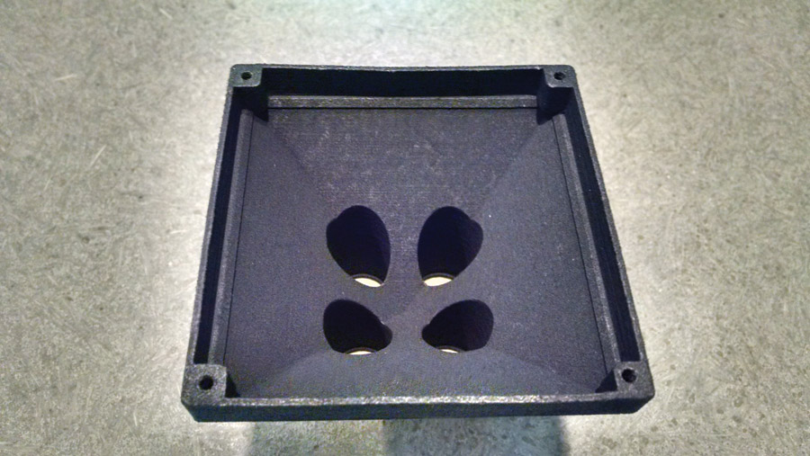
However, the avionics fans have nice, 7/8-inch outlets to connect to scat hose, which feeds into the tube connectors on the back of the avionics trays, whereas the square computer fan is, well…square, which raises the problem of trying to fit a round tube into a square hole.
There are at least two ways to address this problem. One is to use a variety of PVC adapters, fittings, and duct tape from the aviation aisle of the hardware store. While this works, it yields a bulky and not-very-professional-looking installation that cartoonists Heath Robinson or Rube Goldberg would be proud of. A second option is to 3D print an adapter.
If you don’t know how to 3D print, learning will take a small investment of time and a smaller amount of money—something that most Experimental builders have plenty of experience at doing (except maybe the “small amount of money” part).
Confession: I don’t know what I’m doing with 3D printing. I’m a newbie and still have lots to learn. This article will share some of the things learned so far.
3D printing is pretty magical. Draw it on the screen and print out something that can be held in the hand. It’s not terribly difficult, but there are some frustrating parts where the computer absolutely refuses to do the intuitive thing. Some experience in drawing stuff on the computer will definitely come in handy, but it’s not required.
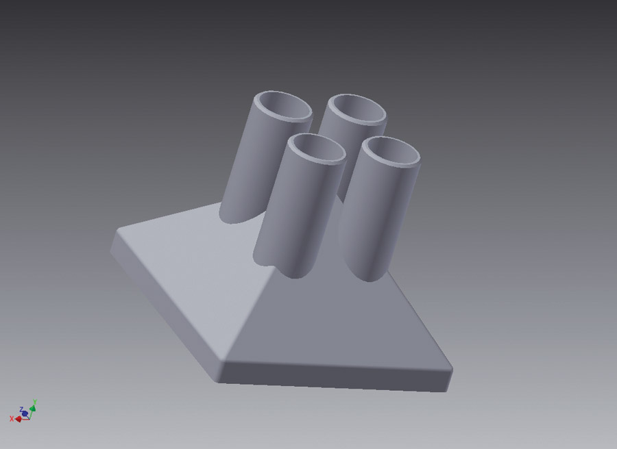
To illustrate how the process works, here is a step-by-step guide to print a four-tube fan adapter shroud using Autodesk’s Inventor 3D CAD (Computer Aided Design) program.
Step 1
Obtain a fan. In this case, the fan used was 80mm (3.15 inches) on a side and was purchased on eBay for under $10. Pay attention to the CFM (Cubic Feet per Minute) ratings; if the shroud will have only one outlet, a high powered fan is probably not required (and a smaller fan might work better). However, if the output is being split into several tubes like in this example, a higher CFM rating (and higher amperage draw and/or larger fan) might be helpful.
Step 2
Measure the fan. This will require a micrometer. 3D printing is now accurate to fractions of an inch, to the point where parts with friction fit and even printed hole threads are possible, although they are crude and not as good as tapped threads. Plan on specifying dimensions to the nearest hundredth of an inch.
Step 3
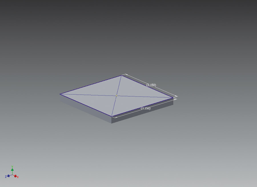
Fire up Inventor and draw a square which matches the outside dimensions of the fan (in this case, 3.15 inches on a side). To do this, you must first select the “plane” that you want to draw the circle on. Most graphs have an “x” and a “y” axis. In 3D CAD, a third axis, the “z” axis is used. If you think of the “x” and “y” axes as being the left/right and up/down axes on a piece of paper, then “z” is the in/out axis. When a 3D printer does its thing, it will be printing on a horizontal table, so I like to start the design on the “x-z” plane and then build it up or down on the “y” axis. Selecting the “x-z” plane is the first step when commencing a new drawing in Inventor.
After drawing a square on the x-z (tabletop) plane (Step 3), extrude the square into a cube (Step 4).
Step 4
Extrude the square into a flat cube. This is the process by which a 2D shape (the square) is stretched into a 3D shape (the cube). It’s actually a pretty easy and fun step. This cube only needs to be deep enough for the mounting screws (e.g. 0.3 inches).
Step 5
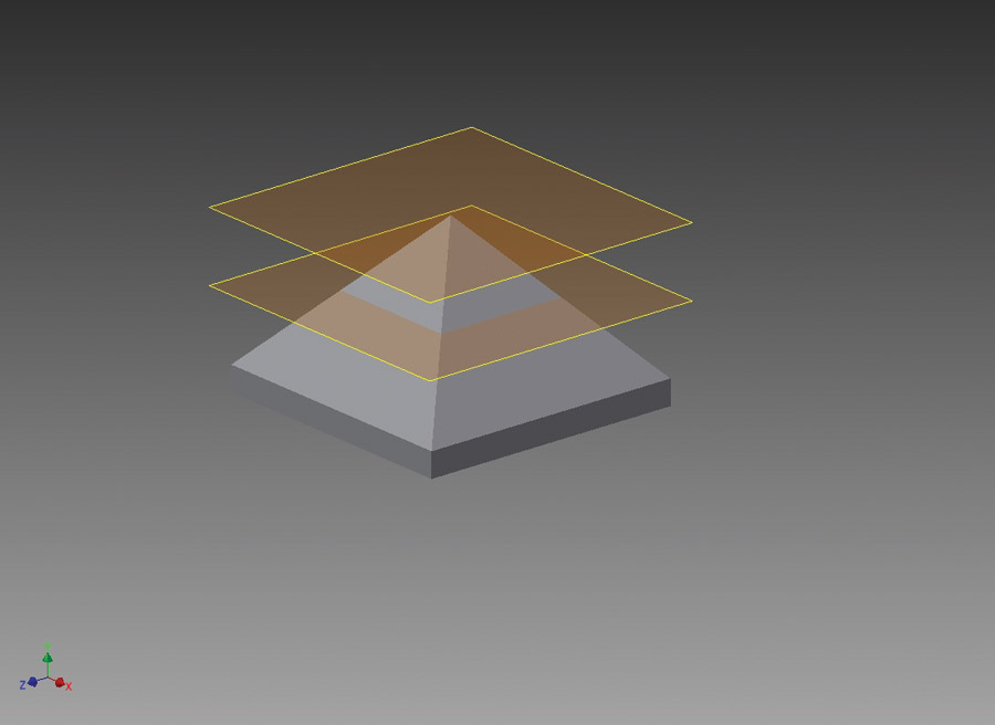
Create a temporary work plane about 2 inches above the x-z plane. The temporary work plane is kind of like a temporary workbench, floating in the air above the main workbench. You can put drawings on the temporary workbench and then connect them to stuff on the main workbench.
Step 6
Put a Point at the center of the temporary work plane.
Step 7
Draw a new square on top of the cube and then loft between the square and the point. Lofting is the process by which two drawings are connected into a single shape. In this case, the square on the bottom is connected to the point at the top, creating a pyramid.
Step 8
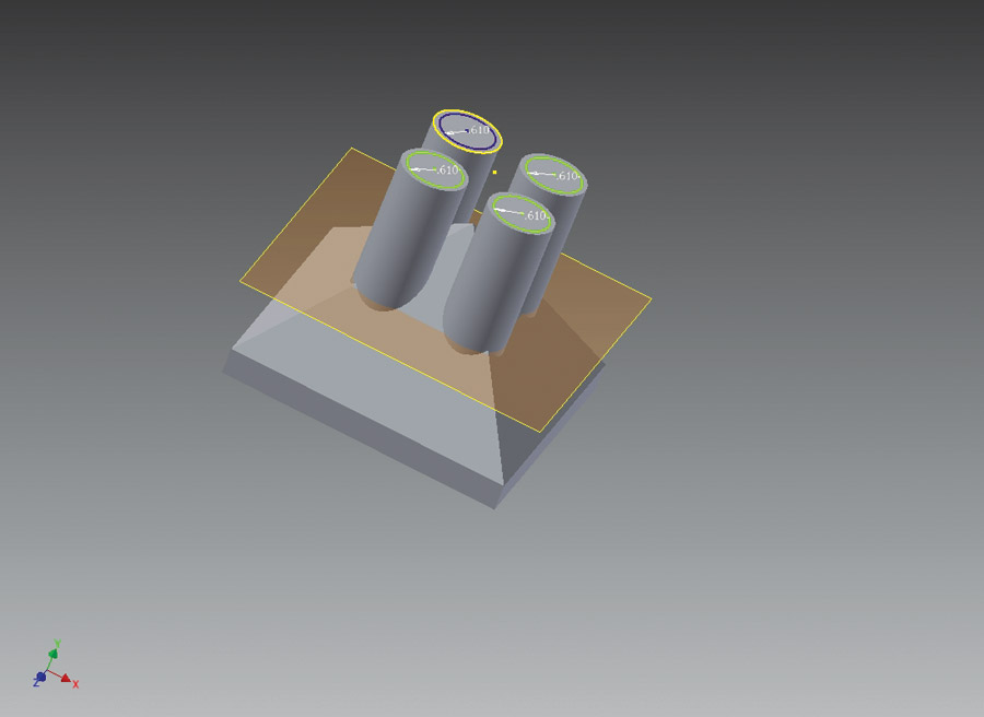
Create another temporary work plane 0.85 inches below the upper work plane. This is where the circles will be drawn for the tubes that the scat hose will connect to.
Step 9
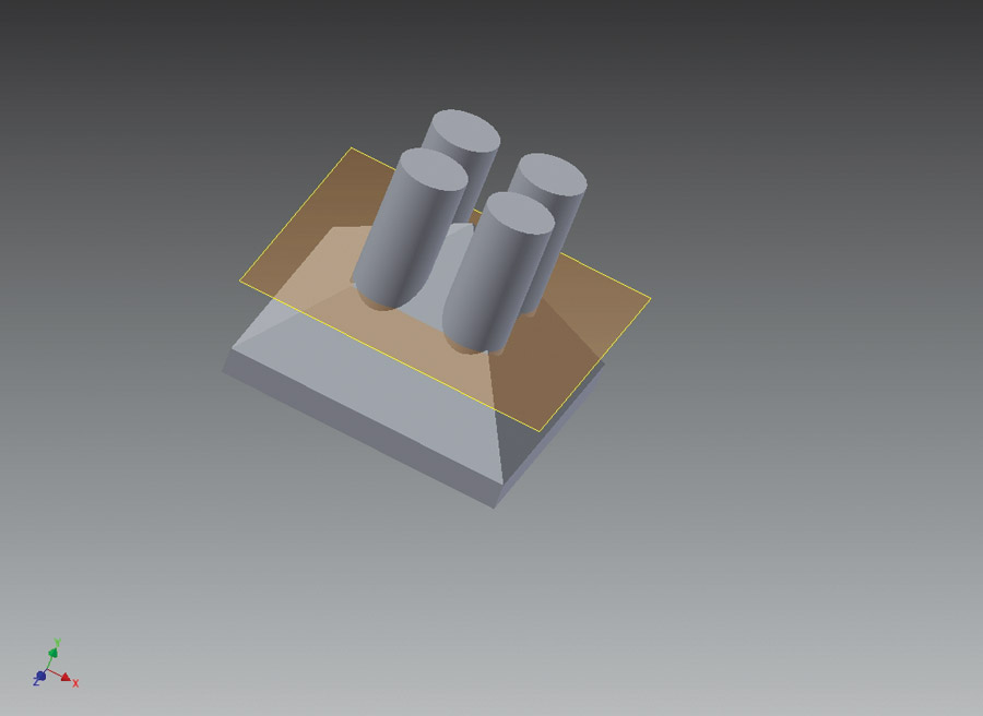
Draw the desired number of circles on the new work plane. In this case, four circles are drawn, each 0.74 inches in diameter (to fit inside a 0.75 inch scat tube). Be sure to allow enough distance between the outside edge of each circle so that the tubes and hose clamps can fit over them. One way to make sure the circles are clustered around the middle of the part and equidistant from each other is to draw a 1-inch square first and then draw the circles with the center of each circle centered on each corner of the square.
Step 10
Extrude the circles 1.5 inches upwards and 0.35 inch downwards. This stretches the circles into cylinders which protrude above the pyramid and extend down into the pyramid. Note that the cylinders need to extend high enough above the pyramid so that a scat tube can be slipped over them without interfering with the sides of the pyramid. It is tempting to lop off the top of the pyramid, but this would create problems when the part is 3D printed (see sidebar: “3D Printing Limitations”).
At this point, the part consists of a solid pyramid with four tubes sticking out of it. However, a solid pyramid isn’t going to pass much air, so the next thing to do is:
Step 11
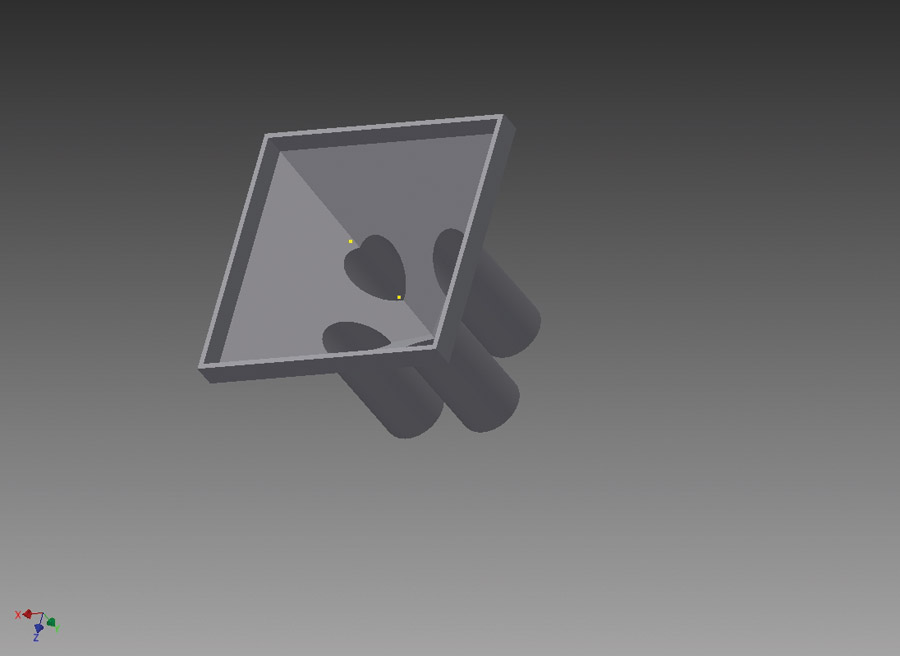
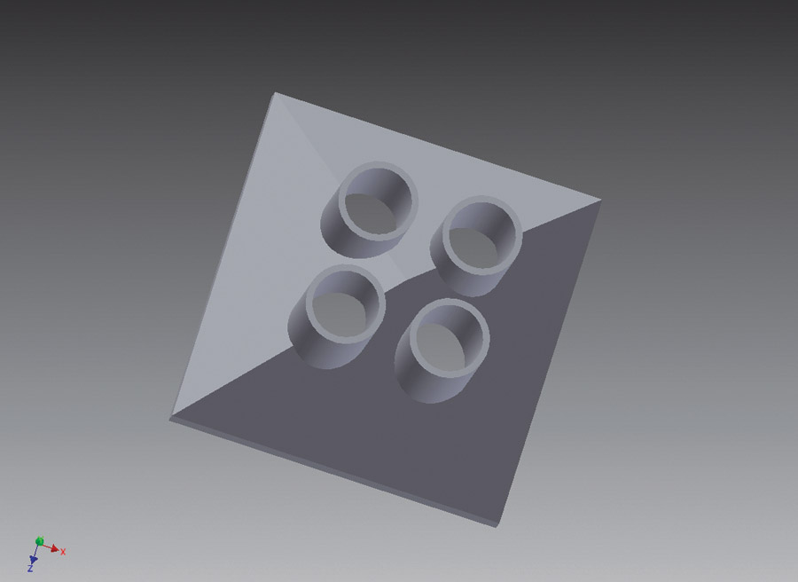
Open the inside of the pyramid, turning it into a shell instead of a solid. Oddly enough, this requires the use of the “shell” function. Select a wall thickness of 0.0625 inch. This will shave the bottom of the cylinders to mate smoothly with the inside walls of the pyramid.
Step 12
Draw circles inside the cylinders. These represent the inside wall of the cylinders. The outside wall is 0.74 inch. If a wall thickness of around 1/16 inch is desired, this means the inside circles should have a diameter of 0.615 inch (0.0625-inch wall, but the wall needs to be all around the cylinder, so this means an inside diameter of 2 x 0.0625 = 0.125 inch).
Step 13
Extrude the inner circles inside the cylinders. However, this will be a “cut” extrusion, which removes material and will be 2.5 inches in length, extending down inside the pyramid, turning the cylinders into tubes.
Step 14
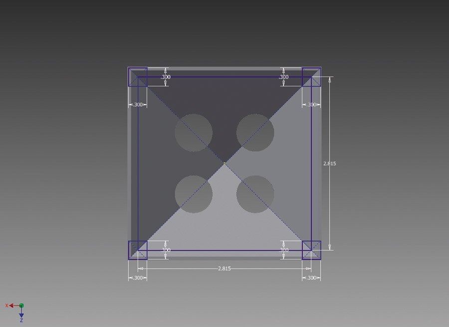
Draw a square on the x-z plane, which is 2.815 inch on each side and centered on the plane. This square will serve as a drawing aid, identifying the corners where the mounting holes will be located (the fan mounting holes are 2.815 inches apart). Draw four new squares that are 0.30 inch on each side, centered at each of the four corners of the 2.815-inch square.
Step 15
Extrude the four new squares 0.3 inch up into the pyramid, forming the “pads” for the mounting holes. Ensure you select the “join” option on the extrusion, otherwise Inventor will try to do it as a cut.
Step 16
Draw a new 2.815-inch square on the bottom of the duct and use the corners to draw four points. Use the points as centers to create four mounting holes. Each hole should be 0.3-inch in depth and should be created with the tapped-hole option, leaving them with a 6-32 thread ready to accept a #6 mounting screw.
Step 17
Apply .0625-inch fillets around the edges of the part to provide a more finished looking part that is more comfortably handled. Apply a 0.03-inch chamfer around the outside lip at the top of the tubes, to help the scat hose slide on more easily.
The finished file can be printed locally or uploaded to an online printing service. If you would like your own duct and don’t want to create the CAD file, you can have it printed by a third-party printing service. Simply go to the file on shapeways.com. They will print it out and mail it to you for a cost of around $35.”


